stop start Seat Leon 5D 2016 Owner's manual
[x] Cancel search | Manufacturer: SEAT, Model Year: 2016, Model line: Leon 5D, Model: Seat Leon 5D 2016Pages: 324, PDF Size: 6.93 MB
Page 4 of 324
Related videos
Lane Assist››› page 213
Start-Stop››› page 191
Storing objects››› page 151
Light Assist››› page 132
Fatigue detection››› page 224
Front Assist››› page 207
Interior lights››› page 138
DSG automatic gearbox››› page 180
Page 7 of 324
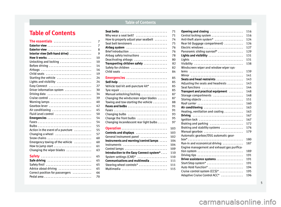
Table of Contents
Table of Contents
The e s
senti
als . . . . . . . . . . . . . . . . . . . . . . . . 7
Exterior view . . . . . . . . . . . . . . . . . . . . . . . . . . . . 7
Exterior view . . . . . . . . . . . . . . . . . . . . . . . . . . . . 8
Interior view (left-hand drive) . . . . . . . . . . . . . . 9
How it works . . . . . . . . . . . . . . . . . . . . . . . . . . . . 10
Unlocking and locking . . . . . . . . . . . . . . . . . . . . 10
Before driving . . . . . . . . . . . . . . . . . . . . . . . . . . . 14
Airbags . . . . . . . . . . . . . . . . . . . . . . . . . . . . . . . . 16
Child seats . . . . . . . . . . . . . . . . . . . . . . . . . . . . . 19
Starting the vehicle . . . . . . . . . . . . . . . . . . . . . . 24
Lights and visibility . . . . . . . . . . . . . . . . . . . . . . 24
Easy Connect . . . . . . . . . . . . . . . . . . . . . . . . . . . 27
Driver information system . . . . . . . . . . . . . . . . . 30
Driving data . . . . . . . . . . . . . . . . . . . . . . . . . . . . 34
Cruise control . . . . . . . . . . . . . . . . . . . . . . . . . . . 39
Warning lamps . . . . . . . . . . . . . . . . . . . . . . . . . . 40
Gearbox lever . . . . . . . . . . . . . . . . . . . . . . . . . . . 42
Air conditioning . . . . . . . . . . . . . . . . . . . . . . . . . 45
Fluid Level control . . . . . . . . . . . . . . . . . . . . . . . 50
Emergencies . . . . . . . . . . . . . . . . . . . . . . . . . . . . 54
Fuses . . . . . . . . . . . . . . . . . . . . . . . . . . . . . . . . . . 54
Bulbs . . . . . . . . . . . . . . . . . . . . . . . . . . . . . . . . . . 55
Action in the event of a puncture . . . . . . . . . . . 55
Changing a wheel . . . . . . . . . . . . . . . . . . . . . . . 57
Snow chains . . . . . . . . . . . . . . . . . . . . . . . . . . . . 60
Emergency towing of the vehicle . . . . . . . . . . . 60
How to jump start . . . . . . . . . . . . . . . . . . . . . . . . 61
Changing the wiper blades . . . . . . . . . . . . . . . . 63
Safety . . . . . . . . . . . . . . . . . . . . . . . . . . . . . . . . 65
Safe driving . . . . . . . . . . . . . . . . . . . . . . . . . . . . 65
Safety first! . . . . . . . . . . . . . . . . . . . . . . . . . . . . . 65
Advice about driving . . . . . . . . . . . . . . . . . . . . . 65
Correct position for passengers . . . . . . . . . . . . 66
Pedal area . . . . . . . . . . . . . . . . . . . . . . . . . . . . . . 70 Seat belts
. . . . . . . . . . . . . . . . . . . . . . . . . . . . . . 71
Why wear a seat belt? . . . . . . . . . . . . . . . . . . . . 71
How to properly adjust your seatbelt . . . . . . . . 74
Seat belt tensioners . . . . . . . . . . . . . . . . . . . . . . 75
Airbag system . . . . . . . . . . . . . . . . . . . . . . . . . . 76
Brief introduction . . . . . . . . . . . . . . . . . . . . . . . . 76
Airbag safety instructions . . . . . . . . . . . . . . . . . 78
Deactivating airbags . . . . . . . . . . . . . . . . . . . . . 80
Transporting children safely . . . . . . . . . . . . . . . 82
Safety for children . . . . . . . . . . . . . . . . . . . . . . . 82
Child seats . . . . . . . . . . . . . . . . . . . . . . . . . . . . . 84
Emergencies . . . . . . . . . . . . . . . . . . . . . . . . . . 85
Self-help . . . . . . . . . . . . . . . . . . . . . . . . . . . . . . . 85
Vehicle tool kit anti-puncture kit* . . . . . . . . . . . 85
Tyre repair . . . . . . . . . . . . . . . . . . . . . . . . . . . . . . 85
Manual unlocking/locking . . . . . . . . . . . . . . . . . 87
Changing the windscreen wiper blades . . . . . . 87
Towing and tow-starting the vehicle . . . . . . . . . 88
Fuses and bulbs . . . . . . . . . . . . . . . . . . . . . . . . . 91
Fuses . . . . . . . . . . . . . . . . . . . . . . . . . . . . . . . . . . 91
Changing bulbs . . . . . . . . . . . . . . . . . . . . . . . . . 93
Change the front bulbs . . . . . . . . . . . . . . . . . . . 95
Changing incandescent rear light bulbs . . . . . . 97
Operation . . . . . . . . . . . . . . . . . . . . . . . . . . . . . 103
Controls and displays . . . . . . . . . . . . . . . . . . . . 103
General instrument panel . . . . . . . . . . . . . . . . . 102
Instruments and warning/control lamps . . . . . 104
Instruments . . . . . . . . . . . . . . . . . . . . . . . . . . . . 104
Control lamps . . . . . . . . . . . . . . . . . . . . . . . . . . . 109
Introduction to the Easy Connect system* . . . . 110
System settings (CAR)* . . . . . . . . . . . . . . . . . . . 110
Communications and multimedia . . . . . . . . . . . 111
Steering wheel controls* . . . . . . . . . . . . . . . . . . 111
Multimedia . . . . . . . . . . . . . . . . . . . . . . . . . . . . . 115 Opening and closing
. . . . . . . . . . . . . . . . . . . . . 116
Central locking system . . . . . . . . . . . . . . . . . . . . 116
Anti-theft alarm system* . . . . . . . . . . . . . . . . . . 124
Rear lid (luggage compartment) . . . . . . . . . . . . 126
Electric windows . . . . . . . . . . . . . . . . . . . . . . . . . 127
Panoramic sliding sunroof* . . . . . . . . . . . . . . . . 129
Lights and visibility . . . . . . . . . . . . . . . . . . . . . . 131
Lights . . . . . . . . . . . . . . . . . . . . . . . . . . . . . . . . . 131
Visibility . . . . . . . . . . . . . . . . . . . . . . . . . . . . . . . 138
Windscreen wiper and window wiper sys-
tems . . . . . . . . . . . . . . . . . . . . . . . . . . . . . . . . . . 139
Mirr
or . . . . . . . . . . . . . . . . . . . . . . . . . . . . . . . . . 141
Seats and head restraints . . . . . . . . . . . . . . . . . 143
Adjusting the seats and headrests . . . . . . . . . . 143
Seat functions . . . . . . . . . . . . . . . . . . . . . . . . . . 144
Transport and practical equipment . . . . . . . . . 148
Storage compartments . . . . . . . . . . . . . . . . . . . 148
Storing objects . . . . . . . . . . . . . . . . . . . . . . . . . . 151
Roof carrier . . . . . . . . . . . . . . . . . . . . . . . . . . . . . 160
Air conditioning . . . . . . . . . . . . . . . . . . . . . . . . . 163
Heating, ventilation and cooling . . . . . . . . . . . . 163
Driving . . . . . . . . . . . . . . . . . . . . . . . . . . . . . . . . 167
Ignition lock . . . . . . . . . . . . . . . . . . . . . . . . . . . . 167
Braking and parking . . . . . . . . . . . . . . . . . . . . . 172
Braking and stability systems . . . . . . . . . . . . . . 176
Manual gearbox . . . . . . . . . . . . . . . . . . . . . . . . . 179
Automatic gearbox/DSG automatic gear-
box* . . . . . . . . . . . . . . . . . . . . . . . . . . . . . . . . . . . 180
R
un-in and economical driving . . . . . . . . . . . . . 187
Engine management and exhaust gas purifica-
tion syst
em . . . . . . . . . . . . . . . . . . . . . . . . . . . . . 189
Driving tips . . . . . . . . . . . . . . . . . . . . . . . . . . . . . 191
Driver assistance systems . . . . . . . . . . . . . . . . . 191
Start-Stop system* . . . . . . . . . . . . . . . . . . . . . . . 191
Auto Hold Function* . . . . . . . . . . . . . . . . . . . . . . 194
Cruise control system (CCS)* . . . . . . . . . . . . . . . 195
Adaptive Cruise Control ACC* . . . . . . . . . . . . . . 196
5
Page 26 of 324
The essentials
● Pu
sh the loc
k and release it from the an-
choring support.
››› in Safety instructions on page 84 Starting the vehicle
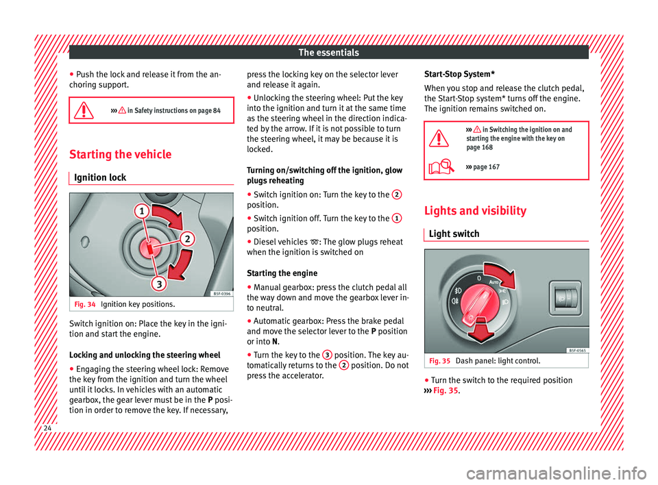
Ignition lock Fig. 34
Ignition key positions. Switch ignition on: Place the key in the igni-
tion and s
t
ar
t the engine.
Locking and unlocking the steering wheel
● Engaging the steering wheel lock: Remove
the key fr
om the ignition and turn the wheel
until it locks. In vehicles with an automatic
gearbox, the gear lever must be in the P posi-
tion in order to remove the key. If necessary, press the locking key on the selector lever
and rele
ase it again.
● Unlocking the steering wheel: Put the key
into the ignition and turn it
at the same time
as the steering wheel in the direction indica-
ted by the arrow. If it is not possible to turn
the steering wheel, it may be because it is
locked.
Turning on/switching off the ignition, glow
plugs reheating
● Switch ignition on: Turn the key to the 2 position.
●
Switch ignition off. Turn the key to the 1 position.
●
Diesel vehicles : The glo
w p
lugs reheat
when the ignition is switched on
Starting the engine
● Manual gearbox: press the clutch pedal all
the way
down and move the gearbox lever in-
to neutral.
● Automatic gearbox: Press the brake pedal
and move the sel
ector lever to the P position
or into N.
● Turn the key to the 3 position. The key au-
t om
atic
ally returns to the 2 position. Do not
pr e
s
s the accelerator. Start-Stop System*
When you s
top and release the clutch pedal,
the Start-Stop system* turns off the engine.
The ignition remains switched on.
››› in Switching the ignition on and
starting the engine with the key on
page 168
››› page 167 Lights and visibility
Light sw
it
ch Fig. 35
Dash panel: light control. ●
Turn the switch to the required position
› ›
›
Fig. 35. 24
Page 36 of 324
The essentials
Driving data M emor
y The MFD (multifunction display) shows differ-
ent
v
alues for the journey and the consump-
tion.
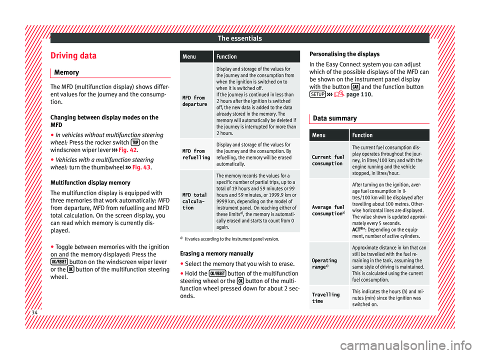
Changing between display modes on the
MFD
● In vehicles without multifunction steering
wheel:
Press the rocker switch on the
wind s
creen wiper lever ›››
Fig. 42.
● Vehicles with a multifunction steering
whee l:
turn the thumbwheel ›››
Fig. 43.
Multifunction display memory
The multifunction display is equipped with
three memories that work automatically: MFD
from departure, MFD from refuelling and MFD
total calculation. On the screen display, you
can read which memory is currently dis-
played.
● Toggle between memories with the ignition
on and the memory di
splayed: Press the
button on the windscreen wiper lever
or the button of the multifunction steering
wheel .
MenuFunction
MFD from
departure
Display and storage of the values for
the journey and the consumption from
when the ignition is switched on to
when it is switched off.
If the journey is continued in less than
2 hours after the ignition is switched
off, the new data is added to the data
already stored in the memory. The
memory will automatically be deleted if
the journey is interrupted for more than
2 hours.
MFD from refuellingDisplay and storage of the values for
the journey and the consumption. By
refuelling, the memory will be erased
automatically.
MFD total
calcula-
tion
The memory records the values for a
specific number of partial trips, up to a
total of 19 hours and 59 minutes or 99
hours and 59 minutes, or 1999.9 km or
9999 km, depending on the model of
instrument panel. On reaching either of
these limits a)
, the memory is automati-
cally erased and starts to count from 0
again.
a) It varies according to the instrument panel version.
Erasing a memory manually
● Select the memory that you wish to erase.
● Hold the button of the multifunction
s t
eerin
g wheel or the button of the multi-
f u nction wheel
pressed down for about 2 sec-
onds. Personalising the displays
In the Easy
Connect system you can adjust
which of the possible displays of the MFD can
be shown on the instrument panel display
with the button and the function button
S ETUP
› ››
p
age 110.
Dat
a summary
MenuFunction
Current fuel
consumption
The current fuel consumption dis-
play operates throughout the jour-
ney, in litres/100 km; and with the
engine running and the vehicle
stopped, in litres/hour.
Average fuel consumption a)
After turning on the ignition, aver-
age fuel consumption in li-
tres/100 km will be displayed after
travelling about 100 metres. Other-
wise horizontal lines are displayed.
The value shown is updated approxi-
mately every 5 seconds.
ACT®
*: Depending on the equip-
ment, number of active cylinders.
Operating range a)
Approximate distance in km that can
still be travelled with the fuel re-
maining in the tank, assuming the
same style of driving is maintained.
This is calculated using the current
fuel consumption.
Travelling
timeThis indicates the hours (h) and mi-
nutes (min) since the ignition was
switched on. 34
Page 38 of 324

The essentials
● Oper ation with
the
multi-function steering
wheel*: Move with the buttons 1 or
2 to
Driving data and enter w
ith
OK . Turn the
thumbwheel to the right until the Conven-
ience consumers display appears.
In addition, a scale will inform you of the cur-
rent sum of all the additional appliances.
Saving tips Tips on how to save fuel will be displayed in
c
ondition
s
that increase fuel consumption.
Follow them to reduce consumption. The indi-
cations appear automatically only with the ef-
ficiency programme. After a time, the tips will
disappear automatically.
If you wish to hide a saving tip immediately
after it appears, press any button on the
windscreen wiper lever*/multifunction steer-
ing wheel*. Note
● If y
ou hide a saving tip, it will reappear af-
ter you switch the ignition on again.
● The saving tips do not appear in all situa-
tions, but
rather with a large separation of
time. Timer*
You can access the timer via the selection
menu
›››
page 31.
It allows you to manually time lap times on a
racing circuit, memorise them and compare
them to the vehicle's previous best times.
The following menus can be displayed:
● Stop
● Lap
● Pause
● Partial time
● Statistics
Chang
e from one menu to another
● Vehicles without multifunction steering
whee l:
press the rocker switch in the
w ind
s
creen wiper lever.
● Vehicles with multifunction steering wheel:
pres
s or
.
Menu “Stop”
Start
The timer starts.
If there are existing laps and they are in-
cluded in the statistics, it will begin with
the number of laps in question.
It is only possible to begin with a new
first lap if the statistics have been reset
first in the
Statistics menu.
Menu “Stop”
Since
startThe timer begins when the vehicle sets
off.
If the vehicle is already moving, the timer
begins once the vehicle has stopped.
Statis-
ticsThe Statistics menu is displayed on
the screen.
Menu “Lap”
New lap
The timer of the current lap stops and a
new lap starts immediately. The time for
the lap you have just completed is inclu-
ded in the statistics.
Partial timeFor about 5 seconds a partial time is dis-
played. The timer continues in parallel.
StopThe current lap timer will be interrupted.
The lap does not end. The Pause menu
is displayed.
Menu “Pause”
ContinueThe interrupted timer continues.
New lapA new timer starts. The halted lap ends
and is included in the statistics.
Interr. lapThe timer of the current lap ends and is
cancelled. It is not included in the statis-
tics.
EndThe current timer ends. The lap is inclu-
ded in the statistics. 36
Page 39 of 324
The essentialsMenu “Partial time”
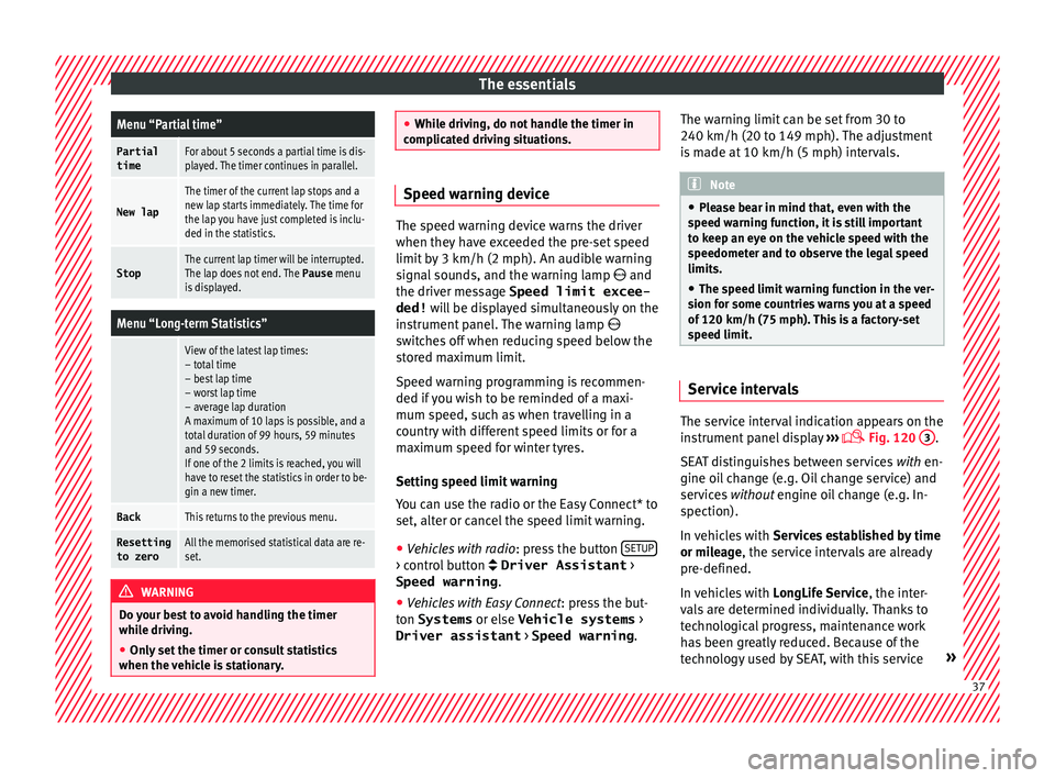
Partial
timeFor about 5 seconds a partial time is dis-
played. The timer continues in parallel.
New lap
The timer of the current lap stops and a
new lap starts immediately. The time for
the lap you have just completed is inclu-
ded in the statistics.
StopThe current lap timer will be interrupted.
The lap does not end. The
Pause menu
is displayed.
Menu “Long-term Statistics”
View of the latest lap times:
– total time
– best lap time
– worst lap time
– average lap duration
A maximum of 10 laps is possible, and a
total duration of 99 hours, 59 minutes
and 59 seconds.
If one of the 2 limits is reached, you will
have to reset the statistics in order to be-
gin a new timer.
BackThis returns to the previous menu.
Resetting
to zeroAll the memorised statistical data are re-
set. WARNING
Do your best to avoid handling the timer
whil e driv
ing.
● Only set the timer or consult statistics
when the vehic
le is stationary. ●
Whil e driv
ing, do not handle the timer in
complicated driving situations. Speed warning device
The speed warning device warns the driver
when they h
av
e exceeded the pre-set speed
limit by 3 km/h (2 mph). An audible warning
signal sounds, and the warning lamp and
the driver message Speed limit excee-
ded! will be displayed simultaneously on the
instrument panel. The warning lamp
switches off when reducing speed below the
stored maximum limit.
Speed warning programming is recommen-
ded if you wish to be reminded of a maxi-
mum speed, such as when travelling in a
country with different speed limits or for a
maximum speed for winter tyres.
Setting speed limit warning
You can use the radio or the Easy Connect* to
set, alter or cancel the speed limit warning.
● Vehicles with radio : pres
s the button SETUP > control button Driver Assistant
>
Speed warning .
● Vehicles with Easy Connect : pre
s
s the but-
ton Systems or else Vehicle systems >
Driver assistant > Speed warning.The warning limit can be set from 30 to
240 km/h (20 to 149 mph). The a
djustment
is made at 10 km/h (5 mph) intervals. Note
● Ple a
se bear in mind that, even with the
speed warning function, it is still important
to keep an eye on the vehicle speed with the
speedometer and to observe the legal speed
limits.
● The speed limit warning function in the ver-
sion for some c
ountries warns you at a speed
of 120 km/h (75 mph). This is a factory-set
speed limit. Service intervals
The service interval indication appears on the
in
s
trument
panel display ›››
Fig. 120
3 .
S EA
T di
stinguishes between services with en-
gine oil change (e.g. Oil change service) and
services without engine oil change (e.g. In-
spection).
In vehicles with Services established by time
or mileage, the service intervals are already
pre-defined.
In vehicles with LongLife Service , the inter-
vals are determined individually. Thanks to
technological progress, maintenance work
has been greatly reduced. Because of the
technology used by SEAT, with this service » 37
Page 44 of 324
The essentials
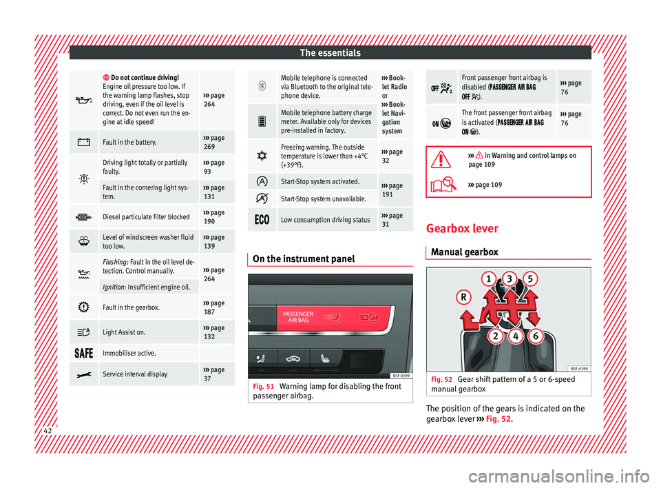
Do not continue driving!
Engine oil pressure too low. If
the warning lamp flashes, stop
driving, even if the oil level is
correct. Do not even run the en-
gine at idle speed!
››› page
264
Fault in the battery.›››
page
269
Driving light totally or partially
faulty.›››
page
93
Fault in the cornering light sys-
tem.››› page
131
Diesel particulate filter blocked›››
page
190
Level of windscreen washer fluid
too low.›››
page
139
Flashing: Fault in the oil level de-
tection. Control manually.›››
page
264
Ignition: Insufficient engine oil.
Fault in the gearbox.›››
page
187
Light Assist on.›››
page
132
Immobiliser active.
Service interval display›››
page
37
Mobile telephone is connected
via Bluetooth to the original tele-
phone device.›››
Book-
let Radio
or
››› Book-
let Navi-
gation
system
Mobile telephone battery charge
meter. Available only for devices
pre-installed in factory.
Freezing warning. The outside
temperature is lower than +4°C
(+39°F).›››
page
32
Start-Stop system activated.›››
page
191
Start-Stop system unavailable.
Low consumption driving status›››
page
31 On the instrument panel
Fig. 51
Warning lamp for disabling the front
p a
s
senger airbag.
Front passenger front airbag is
disabled (
).
››› page
76
The front passenger front airbag
is activated (
).
››› page
76
››› in Warning and control lamps on
page 109
››› page 109 Gearbox lever
M anua
l
gearbox Fig. 52
Gear shift pattern of a 5 or 6-speed
m anual
g
earbox The position of the gears is indicated on the
g
e
arbo
x lever ››› Fig. 52.42
Page 58 of 324

The essentials
Repairing a tyre with the anti-punc-
t ur
e k
it Fig. 67
Standard representation: contents of
the anti-p u
nct
ure kit. The anti-puncture kit is located under the
floor p
anel
in the lug
gage compartment.
Sealing the tyre
● Unscrew the tyre valve cap and insert. Use
the ›››
Fig. 67 1 tool to remove the insert.
Pl ac
e it
on a clean surface.
● Shake the tyre sealant bottle vigorously
›››
Fig. 67 10 .
● Screw the inflator tube ››
›
Fig. 67 3 into
the se al
ant
bottle. The bottle's seal will break
automatically. ●
Remov
e the lid from the filling tube
››› Fig. 67 3 and screw the open end of the
t ube int
o the ty
re valve.
● With the tyre sealant bottle upside down,
fill
the tyre with the contents of the sealant
bottle.
● Remove the bottle from the valve.
● Place the insert back into the tyre valve us-
ing the too
l ››› Fig. 67 1 .
Infl atin
g the ty
re
● Screw the compressor tyre inflator tube
›››
Fig. 67 5 into the tyre valve.
● Check that the air bleed screw is closed
› ›
›
Fig. 67 7 .
● Start the engine and leave it running.
● Insert the connector ››
›
Fig. 67 9 into the
v ehic
l
e's 12-volt socket ›››
page 150.
● Turn the air compressor on with the ON/OFF
switc
h ››› Fig. 67 8 .
● Keep the air compressor running until it
r e
ac
hes 2.0 to 2.5 bar
(29-36 psi/200-250 kPa). A maximum of 8
minutes.
● Disconnect the air compressor.
● If it does not reach the pressure indicated,
uns
crew the tyre inflator tube from the valve.
● Move the vehicle 10m so that the sealant is
dis trib
uted throughout the tyre. ●
Scr ew the c
ompressor tyre inflator into the
valve.
● Repeat the inflation process.
● If the indicated pressure still cannot be
reac
hed, the tyre is too badly damaged. Stop
and request assistance from an authorised
technician.
● Disconnect the air compressor. Unscrew
the tyre infl
ator tube from the tyre valve.
● When the tyre pressure is between 2.5 and
2.0 bars, c
ontinue driving without exceeding
80 km/h (50 mph).
● Check the pressure again after 10 minutes
›››
page 87.
››› in TMS (Tyre Mobility System)* on
page 85
››› page 85 56
Page 64 of 324
The essentials
Jump leads must comply with standard DIN
72553 (see c ab
l
e manufacturer's instruc-
tions). The wire cross section must be at least
25 mm 2
for petrol engines and at least
35 mm 2
for diesel engines. Note
● The v ehic
les must not touch each other,
otherwise electricity could flow as soon as
the positive terminals are connected.
● The discharged battery must be properly
connected t
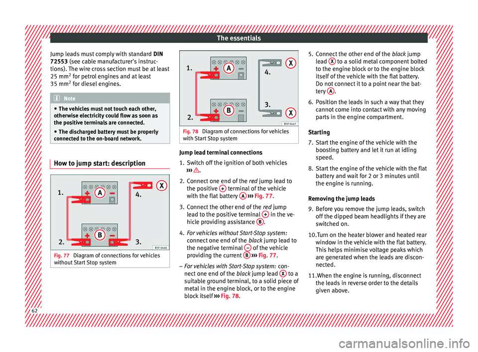
o the on-board network. How to jump start: description
Fig. 77
Diagram of connections for vehicles
w ithout
Start Stop system Fig. 78
Diagram of connections for vehicles
with St
art Stop system Jump lead terminal connections
1. Switch off the ignition of both vehicles
››
›
.
2. Connect one end of the re
d
jump lead to
the positive + terminal of the vehicle
w ith the fl
at
battery A
› ›
› Fig. 77 .
3. Connect the other end of the red
jump
lead to the positive terminal + in the ve-
hic l
e pr
oviding assistance B .
4. For vehicles without Start-Stop system:
connect
one end of
the black jump lead to
the negative terminal – of the vehicle
pr o
v
iding the current B
› ›
› Fig. 77 .
– For vehicles with Start-Stop system: con-
nect one end of
the black jump lead X to a
s uit
ab
le ground terminal, to a solid piece of
metal in the engine block, or to the engine
block itself ››› Fig. 78. 5. Connect the other end of the
black
jump
lead X to a solid metal component bolted
t o the en
gine b
lock or to the engine block
itself of the vehicle with the flat battery.
Do not connect it to a point near the bat-
tery A .
6. Position the leads in such a way that they cannot
c
ome into contact with any moving
parts in the engine compartment.
Starting
7. Start the engine of the vehicle with the boostin
g battery and let it run at idling
speed.
8. Start the engine of the vehicle with the flat batter
y and wait for 2 or 3 minutes until
the engine is running.
Removing the jump leads
9. Before you remove the jump leads, switch off the dipped be
am headlights if they are
switched on.
10.
Turn on the heater blower and heated rear
window in the vehicle with the flat battery.
This helps minimise voltage peaks which
are generated when the leads are discon-
nected.
11.When the engine is running, disconnect the lea
ds in reverse order to the details
given above. 62
Page 87 of 324

Self-help
Emergencies
Self -help
V ehic
le tool kit anti-puncture kit* The tools and anti-puncture kit* are stored
under the floor p
anel
in the luggage compart-
ment.
To access the vehicle tools:
– Lift up the floor surface by the plastic han-
dle u nti
l it is fastened to the tabs on both
sides.
Depending on the vehicle equipment, the an-
ti-puncture kit* is located under the floor
panel in the luggage compartment.
The tool kit includes:
● Jack*
● Wire hook for pulling off the wheel cov-
er*/wheel bolt
cap clip.
● Box spanner for wheel bolts*
● Towline anchorage
● Adapter for the anti-theft wheel bolts*
● Towing bracket device
Some of the items
listed are only provided in
certain model versions, or are optional ex-
tras. Note
The jack does not generally require any main-
ten anc
e. If required, it should be greased us-
ing universal type grease. Tyre repair
TMS (T
yre Mobility System)* Read the additional information carefully
›› ›
page 56
The Anti-puncture kit* (Tyre Mobility System)
will reliably seal punctures caused by the
penetration of a foreign body of up to about
4 mm in diameter. Do not remove foreign ob-
jects, e.g. screws or nails, from the tyre.
After inserting the sealant residue in the tyre,
you must again check the tyre pressure about
10 minutes after starting the engine.
You should only use the tyre mobility set if
the vehicle is parked in a safe place, you are
familiar with the procedure and you have the
necessary tyre mobility set! Otherwise, you
should seek professional assistance.
Do not use the tyre sealant in the following
cases:
● If the wheel rim has been damaged.
● In outside temperatures below -20°C (-4°F). ●
In the ev ent
of
cuts or perforations in the
tyre greater than 4 mm.
● If you have been driving with very low pres-
sure or a c
ompletely flat tyre.
● If the sealant bottle has passed its use by
date. WARNING
Using the tyre mobility system can be dan-
ger ou
s, especially when filling the tyre at the
roadside. Please observe the following rules
to minimise the risk of injury:
● Stop the vehicle safely as soon as possible.
Park it
at a safe distance from surrounding
traffic to fill the tyre.
● Ensure the ground on which you park is flat
and solid.
● Al
l passengers and particularly children
must
keep a safe distance from the work area.
● Turn on the hazard warning lights to warn
other roa
d users.
● Use the tyre mobility system only if you are
famili
ar with the necessary procedures. Oth-
erwise, you should seek professional assis-
tance.
● The tyre mobility set is intended for tempo-
rary
emergency use only until you can reach
the nearest specialised workshop.
● Replace the repaired tyre with the tyre mo-
bility
set as soon as possible. » 85
Technical data
Advice
Operation
Emergencies
Safety