technical specifications Seat Leon SC 2014 Workshop Manual
[x] Cancel search | Manufacturer: SEAT, Model Year: 2014, Model line: Leon SC, Model: Seat Leon SC 2014Pages: 284, PDF Size: 5.85 MB
Page 107 of 284
Lights and visibility
Read the additional information carefully
››› page 13
Synchronized regulation of the exterior
mirrors ● In the Settings - Convenience
menu, sel
ect
whether or not the exterior mirrors should
move in synchronisation.
● Turn the knob to position L 1)
.
● Adjust the left-hand exterior mirror. The
right exterior mirror will be adjusted at the
same time (synchronised).
● If necessary the right exterior mirror adjust-
ment may need correcting. turn the control to
position
R 1)
.
● In the Easy Connect system the exterior mir-
rors can be adjusted using the CAR button
and the function button SETUP .
Tilt function for front passenger exterior
mirror*
When parking backwards, and in order to be
able to see the kerb, the passenger side mir-
ror can be automatically tilted towards the
passenger to provide a better view of the
kerb. The control must be in the position R1)
for this feature to be operational.
The mirror returns to its original position as
soon as you drive forwards at over 15 km/h (10 mph) or switch off the ignition. It also re-
turns to its original position if the position of
the control is adjusted.
Storing the rear view mirror settings for the
tilt function
● Switch the ignition on.
● Access the Easy Connect system, Menu
CAR , function “Rear view mirrors and wind-
screen wipers” and select “lower when re-
versing” ››› page 81 .
● Sel ect
the R1)
position on the control.
● Select reverse gear.
● Adjust the front passenger exterior mirror
so that you can see, for example, the kerb
area well.
● Release the reverse gear.
● The adjusted position for the rear view mir-
ror is stored.
Fold in the exterior mirrors after parking
(convenience function)*
The Easy Connect system, Menu CAR , func-
tion “Rear view mirrors and windscreen wip-
ers” can be used to have the exterior mirrors
fold in when the vehicle is parked ››› page 81.
When the vehicle is locked with the remote
control, by pressing for more than approxi- mately 1 second the exterior mirrors are fol-
ded in automatically. When the vehicle is
opened with the remote control, the exterior
mirrors are deployed automatically. WARNING
Convex or wide-angle* exterior mirrors give a
larger field of vision. However, they make ob-
jects look smaller and further away than they
really are. If you use these mirrors to esti-
mate the distance to vehicles behind you
when changing lane, you could misjudge the
distance. Risk of accident! CAUTION
● If one of the mirror housings is knocked out
of position (e.g. when parking), the mirrors
must first be fully retracted with the electric
control. Do not readjust the mirror housing by
hand, as this will interfere with the mirror ad-
juster function.
● Before washing the vehicle in an automatic
car wash, please make sure to retract the ex-
terior mirrors to prevent them from being
damaged. Electrically retractable exterior
mirrors must not be folded in or out by hand.
Always use the electrical power control. »1)
Regulation in right-hand drive vehicles is symmet-
rical. 105
Technical specifications
Advice
Operation
Safety
The essentials
Page 109 of 284
Seats and head restraints
Adjusting the front head restraints Read the additional information carefully
››› page 12
Adjust the head restraint ›››
page 12 so
that as far as possible the top of the head re-
straint is level with the top of your head.
When this is not possible, try to get as close
as possible to this position.
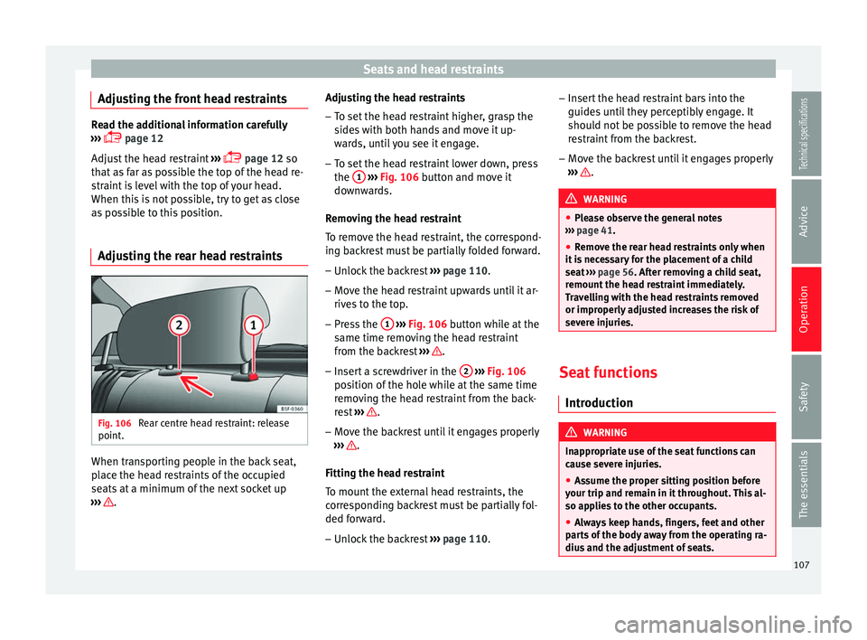
Adjusting the rear head restraints Fig. 106
Rear centre head restraint: release
point. When transporting people in the back seat,
place the head restraints of the occupied
seats at a minimum of the next socket up
››› . Adjusting the head restraints
– To set the head restraint higher, grasp the
sides with both hands and move it up-
wards, until you see it engage.
– To set the head restraint lower down, press
the 1
››› Fig. 106 button and move it
do wn
wards.
Removing the head restraint
To remove the head restraint, the correspond-
ing backrest must be partially folded forward. – Unlock the backrest ››› page 110.
– Move the head restraint upwards until it ar-
rives to the top.
– Press the 1
››› Fig. 106 button while at the
same time removing the head restraint
from the backrest ››› .
– Insert a screwdriver in the 2
››› Fig. 106
position of the hole while at the same time
removing the head restraint from the back-
rest ››› .
– Move the backrest until it engages properly
››› .
Fitting the head restraint
To mount the external head restraints, the
corresponding backrest must be partially fol-
ded forward.
– Unlock the backrest ››› page 110. –
Insert the head restraint bars into the
guides until they perceptibly engage. It
should not be possible to remove the head
restraint from the backrest.
– Move the backrest until it engages properly
››› .
WARNING
● Please observe the general notes
››› page 41.
● Remo
ve the rear head restraints only when
it is necessary for the placement of a child
seat ››› page 56. After removing a child seat,
remou
nt the head restraint immediately.
Travelling with the head restraints removed
or improperly adjusted increases the risk of
severe injuries. Seat functions
Introduction WARNING
Inappropriate use of the seat functions can
cause severe injuries.
● Assume the proper sitting position before
your trip and remain in it throughout. This al-
so applies to the other occupants.
● Always keep hands, fingers, feet and other
parts of the body away from the operating ra-
dius and the adjustment of seats. 107
Technical specifications
Advice
Operation
Safety
The essentials
Page 111 of 284
Seats and head restraints
The armrest can be moved backwards and
forwards.
Folding down the passenger seat
backrest* 3 Applies to the model: LEON ST
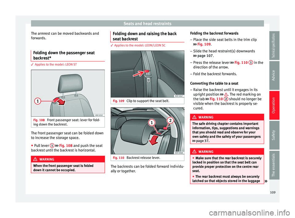
Fig. 108
Front passenger seat: lever for fold-
ing down the backrest. The front passenger seat can be folded down
to increase the storage space.
● Pull lever 1
››› Fig. 108 and push the seat
b ac
krest until the backrest is horizontal. WARNING
When the front passenger seat is folded
down it cannot be occupied. Folding down and raising the back
seat backrest
3 Applies to the model: LEON/LEON SC
Fig. 109
Clip to support the seat belt. Fig. 110
Backrest release lever. The backrests can be folded forward individu-
ally or together.Folding the backrest forwards
– Place the side seat belts in the trim clip
››› Fig. 109 .
– Slide the he a
d restraint(s) downwards
››› page 107.
– Press the release lever ››› Fig. 110 1 in the
direction of the arrow.
– Fold the backrest forwards.
Converting the table to a seat – Raise the backrest until it engages in its
upright position ››› . The red marking on
the tab ››› Fig. 110 2 should no longer be
visible when the backrest is properly se-
cured. WARNING
The safe driving chapter contains important
information, tips, suggestions and warnings
that you should read and observe for your
own safety and the safety of your passengers
››› page 37. WARNING
● Make sure that the rear backrest is securely
locked in position so that the seat belt can
provide proper protection on the centre rear
seat.
● The rear backrest must always be securely
latched so that objects stored in the luggage » 109
Technical specifications
Advice
Operation
Safety
The essentials
Page 113 of 284
Transport and practical equipment
●
For the rear seat seat belts to offer the nec-
essary protection all the parts of the rear
backrest must be properly engaged. This is
particularly important in the case of the cen-
tre rear seat. If someone is seated in a seat
whose backrest is not properly engaged they
will fly forward, along with the backrest, dur-
ing an accident or a sudden driving or braking
manoeuvre.
● A red signal on the button 2 warns that
the backrest is not engaged. Always check
that the red marking is not visible when the
backrest is in the upright position.
● When the rear seat backrest is lowered or is
not properly engaged nobody else can travel
in the corresponding seats (not even a child). CAUTION
Serious damage can be caused to the vehicle
and other objects if the rear seat backrest is
lowered or lifted without due care and atten-
tion.
● Before lowering the rear seat backrest, al-
ways adjust the front seats so that neither
the head restraints nor the cushions of the
rear backrest can hit them. Transport and practical
equipment
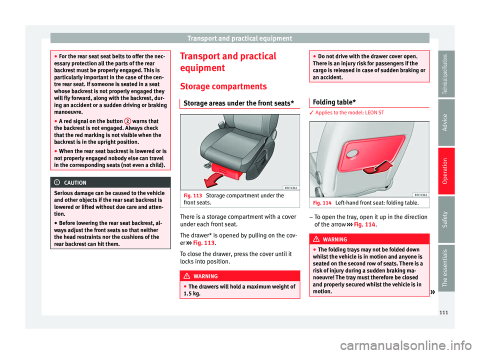
Storage compartments Storage areas under the front seats* Fig. 113
Storage compartment under the
front seats. There is a storage compartment with a cover
under each front seat.
The drawer* is opened by pulling on the cov-
er
››› Fig. 113 .
T o c
lose the drawer, press the cover until it
locks into position. WARNING
● The drawers will hold a maximum weight of
1.5 kg. ●
Do not drive with the drawer cover open.
There is an injury risk for passengers if the
cargo is released in case of sudden braking or
an accident. Folding table*
3 Applies to the model: LEON ST
Fig. 114
Left-hand front seat: folding table. –
To open the tray, open it up in the direction
of the arrow ››› Fig. 114 . WARNING
● The folding trays may not be folded down
whilst the vehicle is in motion and anyone is
seated on the second row of seats. There is a
risk of injury during a sudden braking ma-
noeuvre! The tray must therefore be closed
and properly secured whilst the vehicle is in
motion. » 111
Technical specifications
Advice
Operation
Safety
The essentials
Page 115 of 284
Transport and practical equipment
load of the compartment should not exceed
0.2 kg.
● Coat hooks in the door frames ››› .
● Other storage compartments are found in
the rear seat, to the left and the right of the
seats. WARNING
● Please make sure that any items of clothing
hanging from the coat hooks do not obstruct
your view to the rear.
● The coat hooks should only be used for
lightweight clothing. Do not leave any heavy
or sharp objects in the pockets.
● Do not use clothes hangers to hang up the
clothing, as this could interfere with the func-
tion of the head-protection airbags. Power sockets
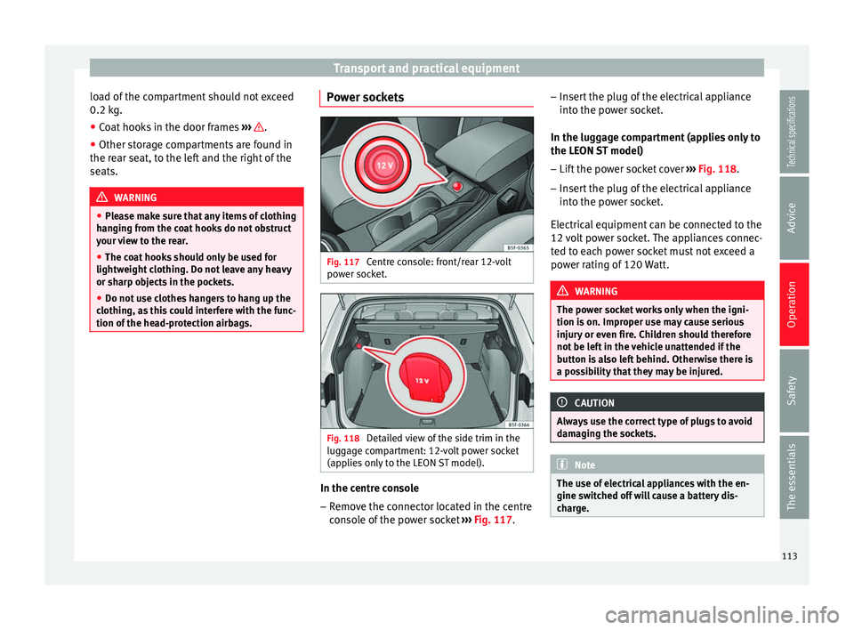
Fig. 117
Centre console: front/rear 12-volt
power socket. Fig. 118
Detailed view of the side trim in the
luggage compartment: 12-volt power socket
(applies only to the LEON ST model). In the centre console
– Remove the connector located in the centre
console of the power socket ››› Fig. 117 . –
Inser t the plug of the electrical appliance
into the power socket.
In the luggage compartment (applies only to
the LEON ST model)
– Lift the power socket cover ››› Fig. 118.
– Inser
t the plug of the electrical appliance
into the power socket.
Electrical equipment can be connected to the
12 volt power socket. The appliances connec-
ted to each power socket must not exceed a
power rating of 120 Watt. WARNING
The power socket works only when the igni-
tion is on. Improper use may cause serious
injury or even fire. Children should therefore
not be left in the vehicle unattended if the
button is also left behind. Otherwise there is
a possibility that they may be injured. CAUTION
Always use the correct type of plugs to avoid
damaging the sockets. Note
The use of electrical appliances with the en-
gine switched off will cause a battery dis-
charge. 113Technical specifications
Advice
Operation
Safety
The essentials
Page 117 of 284
Transport and practical equipment
WARNING
● The luggage compartment cover must al-
ways be fixed properly (risk of accident).
● The luggage compartment cover should not
be used as a storage shelf. Articles placed on
this cover could cause injury to vehicle occu-
pants in an accident or if the brakes are ap-
plied suddenly. Retractable rear shelf
3 Applies to the model: LEON ST
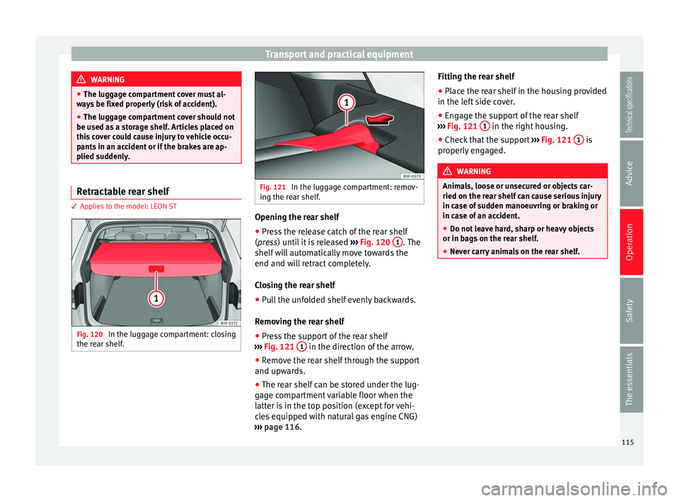
Fig. 120
In the luggage compartment: closing
the rear shelf. Fig. 121
In the luggage compartment: remov-
ing the rear shelf. Opening the rear shelf
● Press the release catch of the rear shelf
( press
) until it is released › ›› Fig. 120 1 . The
shelf will automatically move towards the
end and will retract completely.
Closing the rear shelf
● Pull the unfolded shelf evenly backwards.
Removing the rear shelf
● Press the support of the rear shelf
››› Fig. 121 1 in the direction of the arrow.
● Remove the rear shelf through the support
and upwards.
● The rear shelf can be stored under the lug-
gage compartment variable floor when the
latter is in the top position (except for vehi-
cles equipped with natural gas engine CNG)
››› page 116 . Fittin
g the r
ear shelf
● Place the rear shelf in the housing provided
in the left side cover.
● Engage the support of the rear shelf
››› Fig. 121 1 in the right housing.
● Check that the support ››› Fig. 121 1 is
properly engaged. WARNING
Animals, loose or unsecured or objects car-
ried on the rear shelf can cause serious injury
in case of sudden manoeuvring or braking or
in case of an accident.
● Do not leave hard, sharp or heavy objects
or in bags on the rear shelf.
● Never carry animals on the rear shelf. 115
Technical specifications
Advice
Operation
Safety
The essentials
Page 119 of 284
Transport and practical equipment
Removing the net partition
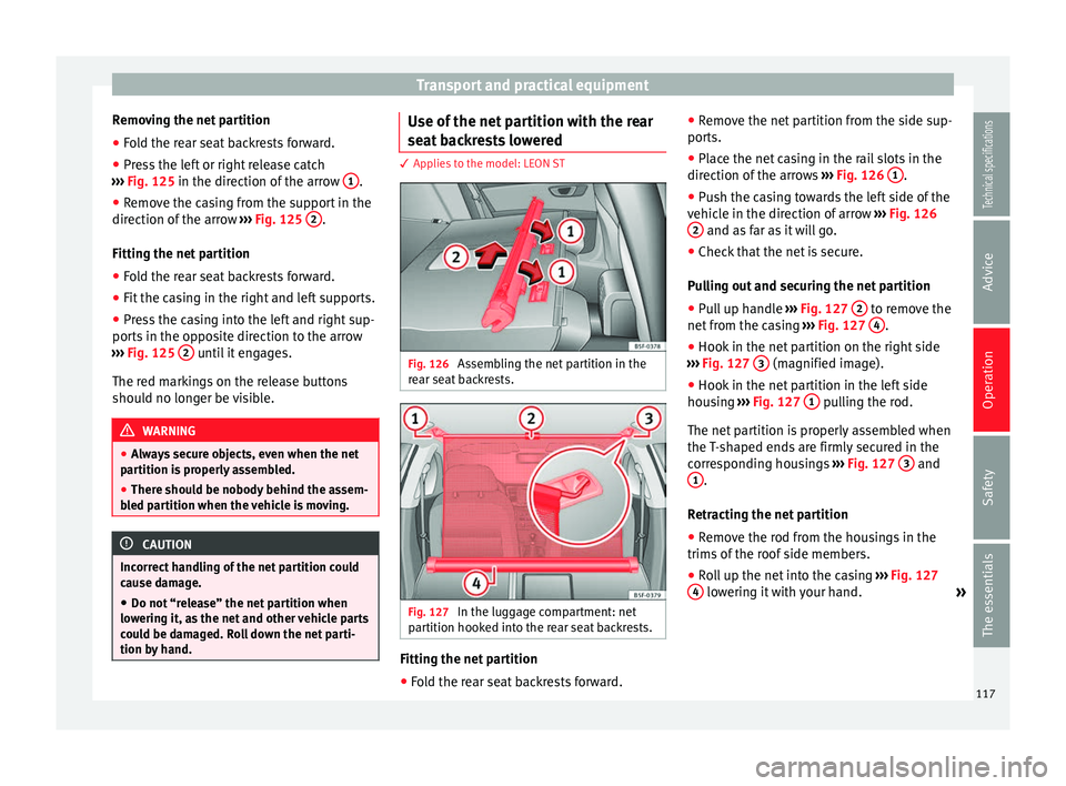
● Fold the rear seat backrests forward.
● Press the left or right release catch
››› Fig. 125 in the direction of the arrow 1 .
● Remove the casing from the support in the
direction of the arrow ››› Fig. 125 2 .
Fitting the net partition
● Fold the rear seat backrests forward.
● Fit the casing in the right and left supports.
● Press the casing into the left and right sup-
ports in the opposite direction to the arrow
››› Fig. 125 2 until it engages.
The red markings on the release buttons
should no longer be visible. WARNING
● Always secure objects, even when the net
partition is properly assembled.
● There should be nobody behind the assem-
bled partition when the vehicle is moving. CAUTION
Incorrect handling of the net partition could
cause damage. ● Do not “release” the net partition when
lowering it, as the net and other vehicle parts
could be damaged. Roll down the net parti-
tion by hand. Use of the net partition with the rear
seat backrests lowered
3 Applies to the model: LEON ST
Fig. 126
Assembling the net partition in the
rear seat backrests. Fig. 127
In the luggage compartment: net
partition hooked into the rear seat backrests. Fitting the net partition
● Fold the rear seat backrests forward. ●
Remove the net partition from the side sup-
ports.
● Place the net casing in the rail slots in the
direction of the arrows ››› Fig. 126 1 .
● Push the casing towards the left side of the
vehicle in the direction of arrow ››› Fig. 126
2 and as far as it will go.
● Check that the net is secure.
Pulling out and securing the net partition
● Pull up handle ››› Fig. 127 2 to remove the
net from the casing ››› Fig. 127 4 .
● Hook in the net partition on the right side
››› Fig. 127 3 (magnified image).
● Hook in the net partition in the left side
housing ››› Fig. 127 1 pulling the rod.
The net partition is properly assembled when
the T-shaped ends are firmly secured in the
corresponding housings ››› Fig. 127 3 and
1 .
Retracting the net partition
● Remove the rod from the housings in the
trims of the roof side members.
● Roll up the net into the casing ››› Fig. 127
4 lowering it with your hand.
»
117Technical specifications
Advice
Operation
Safety
The essentials
Page 121 of 284
Transport and practical equipment
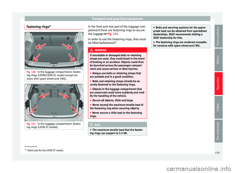
Fastening rings* Fig. 130
In the luggage compartment: fasten-
ing rings (LEON/LEON SC model except ver-
sions with spare wheel and CNG). Fig. 131
In the luggage compartment: fasten-
ing rings (LEON ST model). In the front and rear part of the luggage com-
partment there are fastening rings to secure
the luggage
››› Fig. 131 .
In or der t
o use the fastening rings, they must
be lifted beforehand 1)
. WARNING
If unsuitable or damaged belts or retaining
straps are used, they could break in the event
of braking or an accident. Objects could then
be launched across the passenger compart-
ment and cause serious or fatal injuries.
● Always use belts or retaining straps that
are suitable and in a good condition.
● Belts and retaining straps should be se-
curely fastened to the fastening rings.
● Objects in the luggage compartment that
are unsecured could move suddenly and mod-
ify the handling of the vehicle.
● Secure all objects, little and large.
● Never exceed the maximum tensile load of
the fastening ring when securing objects.
● Never secure a child seat to the fastening
rings. Note
● The maximum tensile load that the fasten-
ing rings can support is 3.5 kN. ●
Belts and securing systems for the appro-
priate load can be obtained from specialised
dealerships. SEAT recommends visiting a
SEAT dealership for this.
● The fastening rings are rendered unusable
for versions with spare wheel and CNG. 1)
Valid only for the LEON ST model.
119
Technical specifications
Advice
Operation
Safety
The essentials
Page 123 of 284
Transport and practical equipment
Hook the net bag next to the load threshold
● Secure the short net hooks to the fastening
rings ››› Fig. 135 1
››› . The bag zip should
be facing upwards.
● Secure the straps in the bag hooks 2 .
Removing the net bag
The hooked up net bag is taut ››› .
● Remove the hooks and the net bag straps
from the fastening rings and from the bag
hooks.
● Store the net bag in the luggage compart-
ment. WARNING
To secure the elastic net bag on the fastening
rings it must be stretched out. Once hooked
up it is taut. If the net bag is hooked up or un-
hooked incorrectly the hooks could cause in-
juries.
● Always secure the net hooks properly so
that they do not suddenly release from the
fastening rings when hooking or unhooking
them.
● On hooking or unhooking them, protect
your eyes and face in case the hooks are re-
leased suddenly.
● Always hook up the net bag hooks in the
described order. If a hook is unexpectedly re-
leased the risk of injury is increased. Luggage compartment variable floor
3 Applies to the model: LEON ST
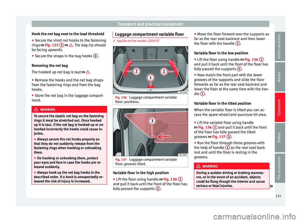
Fig. 136
Luggage compartment variable
floor: positions. Fig. 137
Luggage compartment variable
floor: grooves tilted. Variable floor in the high position
● Lift the floor using handle ››› Fig. 136 1 and pull it back until the front of the floor has
fully passed the supports
2 .●
Move the floor forward over the supports as
far as the rear seat backrest and then lower
the floor with the handle 1 .
Variable floor in the low position
● Lift the floor using handle ››› Fig. 136 1 and pull it back until the front of the floor has
fully passed the supports
2 .
● Now match the front part with the lower
grooves of the supports and slide the floor
forwards as far as the rear seat backrest and
lower the floor at the same time with the han-
dle 1 .
Variable floor in the tilted position
When the variable floor is tilted you can ac-
cess the spare wheel/anti-puncture kit area.
● Lift the variable floor using handle
››› Fig. 136 1 and pull it back until the front
of the floor has fully passed the tilted
grooves ››› Fig. 137 3 .
● Run the floor through these grooves with
the help of handle 1 as the rear seat back-
rest and until the floor is resting in the
grooves. WARNING
During a sudden driving or braking manoeu-
vre, or in the event of an accident, objects
could be flung though the interior and cause
serious or fatal injuries. » 121Technical specifications
Advice
Operation
Safety
The essentials
Page 125 of 284
Transport and practical equipment
Securing the crossbars and the roof
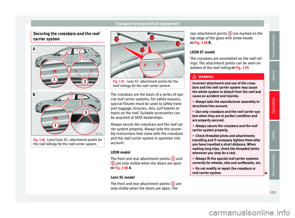
carrier system Fig. 138
Leon/Leon SC: attachment points for
the roof railings for the roof carrier system. Fig. 139
Leon ST: attachment points for the
roof railings for the roof carrier system. The crossbars are the basis of a series of spe-
cial roof carrier systems. For safety reasons,
special fixtures must be used to safely trans-
port luggage, bicycles, skis, surf boards or
boats on the roof. Suitable accessories can
be acquired at SEAT dealerships.
Always secure the crossbars and the roof car-
rier system properly. Always take the assem-
bly instructions that come with the crossbars
and the roof carrier system in question into
account.
LEON model
The front and rear attachment points
1 and
2 are only visible when the doors are open
››› Fig. 138
A.
Leon SC model
The front and rear attachment points 1 are
only visible when the doors are open. The rear attachment points
3 are marked on the
top edge of the glass with arrow heads
››› Fig. 138
B
.
LEON ST model
The crossbars are assembled on the roof rail-
ings. The attachment points can be seen on
bottom of the roof railing ››› Fig. 139. WARNING
Incorrect attachment and use of the cross-
bars and the roof carrier system may cause
the whole system to detach from the roof and
cause an accident and injuries.
● Always take the manufacturer assembly in-
structions into account.
● Use only crossbars and the roof carrier sys-
tem when they are in perfect condition and
are properly secured.
● Always secure the crossbars and the roof
carrier system properly.
● Check threaded joints and attachments
travelling and if necessary tighten them after
you have travelled a short distance. When
making long trips, check the threaded joints
whenever you stop for a rest.
● Always fit the special roof carrier systems
correctly for wheels, skis and surfboards, etc.
● Do not modify or repair the crossbars or
roof carrier system. » 123
Technical specifications
Advice
Operation
Safety
The essentials