change time Seat Leon SC 2015 User Guide
[x] Cancel search | Manufacturer: SEAT, Model Year: 2015, Model line: Leon SC, Model: Seat Leon SC 2015Pages: 308, PDF Size: 5.93 MB
Page 109 of 308

Instruments and warning/control lamps
instructions on the display may vary. In the
ca
se of
displays without warning or informa-
tion texts, faults are indicated exclusively by
the warning lamps.
● Depending on the equipment, some set-
tings
and instructions can also be carried out
in the Easy Connect system.
● When several warnings are active at the
same time, the symbol
s are shown succes-
sively for a few seconds and will stay on until
the fault is rectified. Odometer
Fig. 125
Instrument panel: odometer and re-
set b
utt
on. The distance covered is displayed in “kilome-
tr
e
s” or mi
les “m”. It is possible to change
the measurement units (kilometres
“km”/miles “m”) in the radio/Easy Connect*.
Please refer to the Easy Connect* Instructions
Manual for more details. Odometer/trip recorder
The odometer show
s the total distance cov-
ered by the vehicle.
The trip recorder shows the distance that has
been travelled since it was last reset. It is
used to measure short trips. The last digit of
the trip recorder indicates distances of 100
metres or tenths of a mile.
The trip recorder can be set to zero by press-
ing 0.0/SET
› ››
Fig. 125
.
F
ault display
If there is a fault in the instrument panel, the
letters DEF will appear in the trip recorder
display. Have the fault repaired immediately,
as far as is possible.
Coolant temperature gauge For vehicles with no coolant temperature
g
aug
e, a c
ontrol lamp appears for high
coolant temperatures ›››
page 250. Please
note ››› .
The c oo
l
ant temperature gauge 2 ›››
Fig. 124 only w
orks when the ignition is
switched on. In order to avoid engine dam-
age, please read the following notes for the
different temperature ranges. Engine cold
If on
ly
the diodes in the lower part of the
scale light up, this indicates that the engine
has not yet reached operating temperature.
Avoid high revs and heavy acceleration and
do not make the engine work hard.
Normal temperature
If in normal operations, the diodes light up
until the central zone, it means that the en-
gine has reached operating temperature. At
high outside temperatures and when making
the engine work hard, the diodes may contin-
ue lighting up and reach the upper zone. This
is no cause for concern, provided the control
lamp does not light up on the instrument
panel digital display.
Heat range
When the diodes light up in the upper area of
the display and the control lamp appears
on the instrument panel display, the coolant
temperature is excessive ››› page 250. CAUTION
● To en s
ure a long useful life for the engine,
avoid high revs, driving at high speed and
making the engine work hard for approxi-
mately the first 15 minutes when the engine
is cold. The phase until the engine is warm al-
so depends on the outside temperature. If
necessary, use the engine oil temperature*
››› page 36 as a guide. » 107
Technical data
Advice
Operation
Emergencies
Safety
Page 110 of 308
Operation
●
Addition a
l lights and other accessories in
front of the air inlet reduce the cooling effect
of the coolant. At high outside temperatures
and high engine loads, there is a risk of the
engine overheating.
● The front spoiler also ensures proper distri-
bution of the c
ooling air when the vehicle is
moving. If the spoiler is damaged this can re-
duce the cooling effect, which could cause
the engine to overheat. Seek specialist assis-
tance. Fuel - Gas level
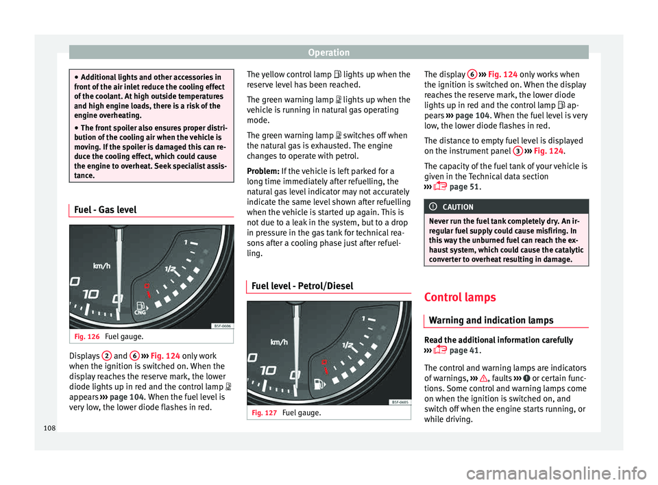
Fig. 126
Fuel gauge. Displays
2 and
6
› ›
› Fig. 124
only work
when the ignition is switched on. When the
display reaches the reserve mark, the lower
diode lights up in red and the control lamp
appears ››› page 104. When the fuel level is
very low, the lower diode flashes in red. The yellow control lamp
lights up when the
re
serve level has been reached.
The green warning lamp lights up when the
vehicle is running in natural gas operating
mode.
The green warning lamp switches off when
the natural gas is exhausted. The engine
changes to operate with petrol.
Problem: If the vehicle is left parked for a
long time immediately after refuelling, the
natural gas level indicator may not accurately
indicate the same level shown after refuelling
when the vehicle is started up again. This is
not due to a leak in the system, but to a drop
in pressure in the gas tank for technical rea-
sons after a cooling phase just after refuel-
ling.
Fuel level - Petrol/Diesel Fig. 127
Fuel gauge. The display
6
› ››
Fig. 124
on ly works when
the ignition is switched on. When the display
reaches the reserve mark, the lower diode
lights up in red and the control lamp ap-
pears ››› page 104. When the fuel level is very
low, the lower diode flashes in red.
The distance to empty fuel level is displayed
on the instrument panel 3
› ››
Fig. 124
.
The c
apacity of the fuel tank of your vehicle is
given in the Technical data section
››› page 51. CAUTION
Never run the fuel tank completely dry. An ir-
re gu
lar fuel supply could cause misfiring. In
this way the unburned fuel can reach the ex-
haust system, which could cause the catalytic
converter to overheat resulting in damage. Control lamps
W arnin
g and indic
ation lamps Read the additional information carefully
› ›
›
page 41.
The control and warning lamps are indicators
of warnings, ››› , faults
››
›
or certain func-
tion s.
Some c
ontrol and warning lamps come
on when the ignition is switched on, and
switch off when the engine starts running, or
while driving.
108
Page 112 of 308
Operation
Introduction to the Easy
C onnect
sy
stem*
System settings (CAR)* CAR menu (Setup) Read the additional information carefully
›› ›
page 28
To select the settings menus, press the Easy
Connect button and the
Set
up function
b utt
on.
The act
ual number of menus available and
the name of the various options in these me-
nus will depend on the vehicle’s electronics
and equipment.
Pressing the menu button will always take
you to the last menu used.
When the function button check box is activa-
ted , the function is active.
Pressing the menu button will always take
y ou t
o the l
ast menu used.
Any changes made using the settings menus
are automatically saved on closing those me-
nus.
Function buttons in the vehicle’s settings
menuPage
ESC system››› page 178
Tyres››› page 259
Driver assistance››› table on page 28
Parking and manoeuvring››› page 211
Vehicle lights››› table on page 28
Rear vision mirrors and wind-
screen wipers››› table on page 28
Opening and closing››› table on page 28
Multifunction display››› table on page 28
Date and time››› table on page 28
Units››› table on page 28
Service››› page 105
Factory settings››› table on page 28 WARNING
Any distraction may lead to an accident, with
the risk of
injury. Operating the Easy Connect
system while driving could distract you from
traffic. 110
Page 115 of 308
Communications and multimedia
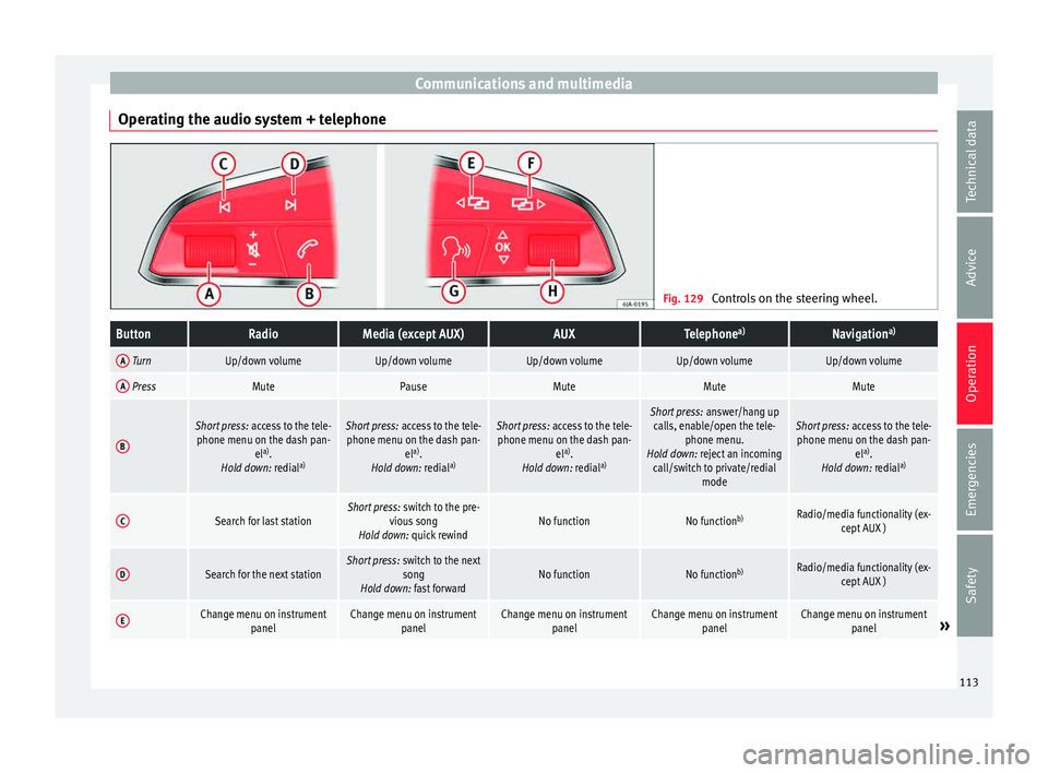
Operating the audio system + telephone Fig. 129
Controls on the steering wheel.ButtonRadioMedia (except AUX)AUXTelephone a)Navigation a)
A TurnUp/down volumeUp/down volumeUp/down volumeUp/down volumeUp/down volume
A PressMutePauseMuteMuteMute
B
Short press:
access to the tele-
phone menu on the dash pan- ela)
.
Hold down: redial a)Short press:
access to the tele-
phone menu on the dash pan- ela)
.
Hold down: redial a)Short press:
access to the tele-
phone menu on the dash pan- ela)
.
Hold down: redial a)Short press:
answer/hang up
calls, enable/open the tele- phone menu.
Hold down: reject an incoming call/switch to private/redial modeShort press: access to the tele-
phone menu on the dash pan- ela)
.
Hold down: redial a)
CSearch for last stationShort press:
switch to the pre-
vious song
Hold down: quick rewindNo functionNo function b)Radio/media functionality (ex-
cept AUX )
DSearch for the next stationShort press: switch to the next
song
Hold down: fast forwardNo functionNo function b)Radio/media functionality (ex-
cept AUX )
EChange menu on instrument panelChange menu on instrumentpanelChange menu on instrumentpanelChange menu on instrumentpanelChange menu on instrumentpanel» 113
Technical data
Advice
Operation
Emergencies
Safety
Page 119 of 308
Opening and closing
Note
● Never l e
ave any valuable items in the vehi-
cle unattended. Even a locked vehicle is not a
safe.
● If the diode on the driver door sill lights up
for about 30 sec
onds when the vehicle is
locked, the central locking system or anti-
theft alarm* is not working properly. You
should have the fault repaired at a SEAT Offi-
cial Service or specialised workshop.
● The vehicle interior monitoring of the anti-
theft a
larm* system will only function as in-
tended if the windows and the sunroof* are
closed. Car key
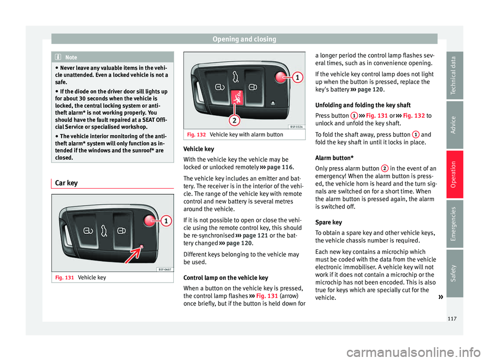
Fig. 131
Vehicle key Fig. 132
Vehicle key with alarm button Vehicle key
W
ith the
v
ehicle key the vehicle may be
locked or unlocked remotely ››› page 116.
The vehicle key includes an emitter and bat-
tery. The receiver is in the interior of the vehi-
cle. The range of the vehicle key with remote
control and new battery is several metres around the vehicle.
If it is not possible to open or close the vehi-
cle using the remote control key, this should
be re-synchronised ››› page 121 or the bat-
tery changed ››› page 120.
Different keys belonging to the vehicle may
be used.
Control lamp on the vehicle key
When a button on the vehicle key is pressed,
the control lamp flashes ››› Fig. 131 (arrow)
once briefly, but if the button is held down for a longer period the control lamp flashes sev-
eral time
s, such as in convenience opening.
If the vehicle key control lamp does not light
up when the button is pressed, replace the
key's battery ››› page 120.
Unfolding and folding the key shaft
Press button 1
› ››
Fig. 131
or ›
›› Fig. 132 to
unlock and unfold the key shaft.
To fold the shaft away, press button 1 and
f o
l
d the key shaft in until it locks in place.
Alarm button*
Only press alarm button 2 in the event of an
emer g
ency!
When the alarm button is press-
ed, the vehicle horn is heard and the turn sig-
nals are switched on for a short time. When
the alarm button is pressed again, the alarm
is switched off.
Spare key
To obtain a spare key and other vehicle keys,
the vehicle chassis number is required.
Each new key contains a microchip which
must be coded with the data from the vehicle
electronic immobiliser. A vehicle key will not
work if it does not contain a microchip or the
microchip has not been encoded. This is also
true for keys which are specially cut for the
vehicle. »
117
Technical data
Advice
Operation
Emergencies
Safety
Page 122 of 308
Operation
Please see Instruction Manual . The
v ehic
le cannot be opened from inside. This
makes it more difficult for unauthorised per-
sons to break into the vehicle ››› in De-
s c
ription on p
age 116.
The anti-theft security system can be switch-
ed off each time the vehicle is locked:
● Turn the key a second time to the lock posi-
tion, in the door lock, f
or the next two sec-
onds. If necessary, remove the protective cov-
er on the driver door handle ›››
page 11
or else
● Press on the remote control key for a
sec ond time
f
or the following 2 seconds.
The flashing frequency of the diode in the
door sill immediately confirms the process.
Initially, the diode flashes in a fast sequence
for a brief period, then it stops for approxi-
mately 30 seconds and, lastly continues
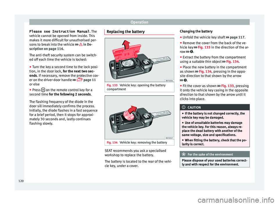
flashing slowly. Replacing the battery Fig. 133
Vehicle key: opening the battery
c omp
ar
tment Fig. 134
Vehicle key: removing the battery SEAT recommends you ask a specialised
w
ork
shop t
o replace the battery.
The battery is located to the rear of the vehi-
cle key, under a cover. Changing the battery
● Unfold the vehicle key shaft ›››
page 117.
● Remove the cover from the back of the ve-
hicle k
ey ››› Fig. 133 in the direction of the ar-
row ››› .
● Extract the battery from the compartment
u s
in
g a suitable thin object ››› Fig. 134.
● Place the new battery in the compartment
as sho
wn ››› Fig. 134, pressing in the oppo-
site direction to that shown by the arrow
››› .
● Fit the cover as shown ››
›
Fig. 133 , pressing
it onto the vehicle key casing in the opposite
direction to that shown by the arrow until it
clicks into place. CAUTION
● If the b att
ery is not changed correctly, the
vehicle key may be damaged.
● Use of unsuitable batteries may damage
the vehic
le key. For this reason, always re-
place the dead battery with another of the
same voltage, size and specifications.
● When fitting the battery, check that the po-
larity i
s correct. For the sake of the environment
Please dispose of your used batteries correct-
ly and w ith r
espect for the environment.120
Page 125 of 308

Opening and closing
their movements will trigger the alarm) or
when, f or e
x
ample, the vehicle is transported
or has to be towed with only one axle on the
ground.
False alarms
Interior monitoring will only operate correctly
if the vehicle is completely closed. Please ob-
serve related legal requirements.
The following cases may cause a false alarm:
● Open windows (partially or fully).
● Panoramic/tilting sunroof open (partially or
compl
etely).
● Movement of objects inside the vehicle,
such a
s loose papers, items hanging from
the rear vision mirror (air fresheners), etc. Note
● If the v
ehicle is relocked and the alarm is
activated without the volumetric sensor func-
tion, relocking will activate the alarm with all
its functions, except the volumetric sensor.
This function is reactivated when the alarm is
switched on again, unless it is deliberately
switched off.
● If the alarm has been triggered by the volu-
metric sensor
, this will be indicated by a
flashing of the warning lamp on the driver
door when the vehicle is opened. The flash is
different to the flash indicating the alarm is
activated. ●
The v ibr
ation of a mobile phone left inside
the vehicle may cause the vehicle interior
monitoring alarm to trigger, as both sensors
react to movements and shakes inside the ve-
hicle.
● If on activating the alarm, any door or the
rear lid i
s open, only the alarm will be activa-
ted. The vehicle interior monitoring and the
anti-tow system will only be activated once
all the doors are closed (including the rear
lid). Deactivating the vehicle interior moni-
t
orin
g and anti-t
ow systems* Fig. 136
Vehicle interior monitoring/tow-
a w
a
y protection button. When the vehicle is locked, the alarm will be
trig
g
er
ed if movements are detected in the
interior (e.g. by animals) or if the vehicle's in-
clination is changed (e.g. during transport).
You can prevent the alarm from being trig- gered accidentally by switching off the vehi-
cle int
erior monitoring and/or tow-away pro-
tection.
– To switch off the vehicle interior monitoring
and tow-
away protection, switch off the ig-
nition and press button ››› Fig. 136. The in-
dicator on the button will light up.
– When the vehicle is locked now, the vehicle
interior monitorin
g and the tow-away pro-
tection are switched off until the next time
the door is opened.
If the anti-theft security system (Safelock)*
››› page 119 is switched off, the vehicle interi-
or monitoring and the tow-away protection
are automatically switched off. WARNING
Observe the safety warnings ›››
in Descrip-
tion on pag e 116
. Rear lid (luggage compart-
ment)
Tai
l
gate automatic lock Where the vehicle has been locked by press-
in
g the button on the remote control with
the r ear lid open, the r
ear lid will lock auto-
matically when closed. »
123
Technical data
Advice
Operation
Emergencies
Safety
Page 132 of 308
Operation
●
If a tr ai
ler turn signal malfunctions, the
control lamp will stop flashing (trailer turn
signals) and the vehicle turn signal will flash
at double speed.
● The main beam headligh
ts can only be
switched on if the dipped beam headlights
are already on.
● In cold or damp weather conditions, the
headlight
s, tail lights and turn signals may
mist up inside temporarily. This is normal and
in no way effects the useful life of the vehicle
lighting system. Automatic dipped beam control
*The automatic dipped beam control is merely
int
ended a
s
an aid and is not able to recog-
nise all driving situations.
When the light switch is in position , the
vehicle lights and the instrument panel and
switch lighting switch on and off automatical-
ly in the following situations ››› in Daytime
ru nnin
g light
s on page 129:
Automatic switching
onAutomatic switching
off
The photo sensor detects
darkness, for example,
when driving through a
tunnel.When adequate lighting is
detected.
Automatic switching
onAutomatic switching
off
The rain sensor detects
rain and activates the
windscreen wipers.When the windscreen wip-
ers have been inactive for
a few minutes. WARNING
If the road is not well lit and other road users
cannot see the
vehicle well enough or at all,
accidents may occur.
● The automatic dipped beam control ( )
only sw
itches on the dipped beam when
there are no changes in brightness, and not,
for example when it is foggy. Main beam assist*
››
›
table on page 2
Main beam assist (Light Assist)
The main beam assist acts within the limits
of the system and depending on environmen-
tal and traffic conditions. Once switched on,
the system is activated as of a speed of
about 60 km/h (37 mph) and is deactivated
below about 30 km/h (18 mph) ››› .
When the sy s
t
em is activated and the camera
detects other vehicles that may be dazzled,
the main beam is automatically switched off.
Otherwise, the main beam is automatically
switched on. The main beam assist generally detects illu-
minated ar
eas and deactivates the main
beam when passing through a town, for ex-
ample.
Switching the main beam assist on and off
Func-
tionAction
Acti-
vate:
– Switch the ignition on and turn the light
switch to position .
– From the base position, move the main
beam and turn signal lever forwards
››› page 129. When the warning lamp
is
displayed on the instrument panel display,
the main beam assist is switched on.
To
switch
system off:
– Switch off the ignition.
– OR: turn the light switch to a different posi-
tion to
››› page 128.
– OR: with main beam on, move the main
beam and turn signal lever backwards.
– OR: move the main beam and turn the sig-
nal lever forwards to manually switch the
main beam on. The main beam assist will then
be deactivated. Malfunctions
The f
o
l
lowing conditions may prevent the
main beam headlight control from turning off
the headlights in time or from turning off al-
together:
● In poorly lit towns with highly reflective
signs.
130
Page 133 of 308

Lights and visibility
● Other in s
uffic
iently lit road users (such as
pedestrians or cyclists).
● On tight bends and steep slopes (bumps)
and when oncoming
vehicles are partially ob-
scured.
● When the drivers of other oncoming vehi-
cle
s (such as a truck) can see over a guard
rail in the centre of the road.
● If the camera is damaged or the power sup-
ply i
s cut off.
● In fog, snow and heavy rain.
● With dust and sand turbulence.
● With loose gravel in the field of vision of
the camera.
● When the fiel
d of vision of the camera is
mist
ed up, dirty or covered by stickers, snow,
ice, etc. WARNING
The convenience features of the main beam
as s
ist should not encourage the taking of
risks. The system is not a replacement for
driver concentration.
● You are always in control of the main beam
and adaptin
g it to the light, visibility and traf-
fic conditions.
● It is possible that the main beam headlight
contro
l does not recognise all driving situa- tions and is limited under certain circumstan-
ce
s.
● When the fiel
d of vision of the camera is
dirty, c
overed or damaged, operation of the
main beam control may be affected. This also
applies when changes are made to the vehi-
cle lighting system, for example, if additional
headlights are installed. CAUTION
To avoid affecting the operation of the sys-
t em, t ak
e the following points into considera-
tion:
● Clean the field of vision of the camera regu-
larly and m
ake sure it is free of snow and ice.
● Do not cover the field of vision of the cam-
era.
● Check
that the windscreen is not damaged
in the area of
the field of vision of the camera. Note
Main beam and headlight flasher can be
turned on and off m
anually at any time with
the turn signal and main beam lever
››› page 129. Fog lights
The warning lamps
or also sho w
, on the
light switch or instrument panel, when the
fog lights are on.
● Switching on front fog lights* : pul
l the
light switch to the first point 1 , from posi-
tions
, or .
● Switching on the rear fog light : com-
pl
etely pull the light switch 2 from position
, or .
● T
o switch off the fog lights, press the light
swit c
h or turn it to position .
Cornering lights* 1) When turning slowly or on very tight bends,
the c
ornerin
g lights
are activated automati-
cally. The cornering lights may be integrated
in the fog lights and are switched on only at
speeds of less than 40 km/h (25 mph).
When reverse gear is engaged, the cornering
lights on both sides of the vehicle switch on,
in order to better illuminate the area for park-
ing. 1)
This function is not available on vehicles equipped
with f u
ll-LED headlights. 131
Technical data
Advice
Operation
Emergencies
Safety
Page 137 of 308
Lights and visibility
Dynamic headlight range control
The c ontr
o
l is not mounted in vehicles with
dynamic headlight range control. The head-
light range is automatically adjusted accord-
ing to the vehicle load status when they are
switched on.
Instrument panel lighting
With the ignition on and without light activa-
tion, the instrument panel lighting remains
activated in daytime light conditions. The
lighting is reduced as the exterior light di-
minishes. In some cases, e.g. when driving
through a tunnel without the function
active, the instrument panel lighting may
even switch off. The objective of this function
is to provide the driver with a visual indica-
tion that he or she should activate the dip-
ped beam. WARNING
Heavy objects in the vehicle may mean that
the hea dlight
s dazzle and distract other driv-
ers. This could result in a serious accident.
● Adjust the light beam to the vehicle load
stat
us so that it does not blind other drivers. Interior and reading lights
1)
›› ›
table on page 2
Read the additional information carefully
››› page 26
Glove compartment and luggage compart-
ment lighting*
When opening and closing the glove com-
partment on the front passenger side and the
rear lid, the respective light will automatically
switch on and off.
Footwell lighting*
The lights in the footwell area below the dash
(driver and front passenger sides) will switch
on when the doors are opened and will de-
crease in intensity while driving. The intensity
of these lights can be adjusted using the ra-
dio menu (see Easy Connect > Adjust-
ing Lighting > Interior lighting
››› page 28).
Ambient light*
The ambient light in the door panel changes
colour (white or red) depending on the driv-
ing mode. The intensity of these lights can be adjusted using the radio menu (see Easy
Connect > Adjusting Lights > In-
terior lighting › ›
›
page 28). Note
The reading lights switch off when the vehi-
cl e i
s locked using a key or after several mi-
nutes if the key is removed from the ignition.
This prevents the battery from discharging. Visibility
Su n
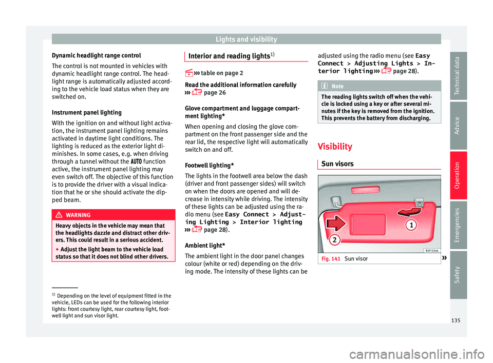
visors Fig. 141
Sun visor »1)
Depending on the level of equipment fitted in the
vehic l
e, LEDs can be used for the following interior
lights: front courtesy light, rear courtesy light, foot-
well light and sun visor light. 135
Technical data
Advice
Operation
Emergencies
Safety