turn signal Seat Leon SC 2015 Owner's Guide
[x] Cancel search | Manufacturer: SEAT, Model Year: 2015, Model line: Leon SC, Model: Seat Leon SC 2015Pages: 308, PDF Size: 5.93 MB
Page 135 of 308
Lights and visibility
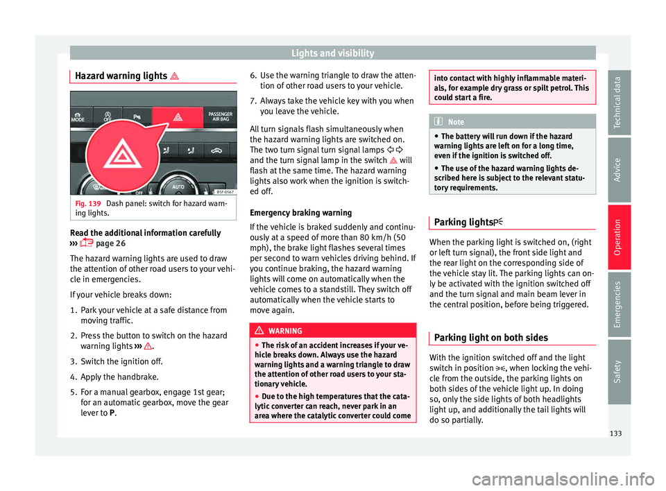
Hazard warning lights Fig. 139
Dash panel: switch for hazard warn-
in g lights. Read the additional information carefully
› ›
›
page 26
The hazard warning lights are used to draw
the attention of other road users to your vehi-
cle in emergencies.
If your vehicle breaks down:
1. Park your vehicle at a safe distance from movin
g traffic.
2. Press the button to switch on the hazard warning lights
››› .
3. Switch the ignition off.
4. Apply the handbrake.
5. For a manual gearbox, engage 1st gear; for an aut
om
atic gearbox, move the gear
lever to P. 6. Use the warning triangle to draw the atten-
tion of other ro
ad users to your vehicle.
7. Always take the vehicle key with you when you le
ave the vehicle.
All turn signals flash simultaneously when
the hazard warning lights are switched on.
The two turn signal turn signal lamps
and the turn signal lamp in the switch will
flash at the same time. The hazard warning
lights also work when the ignition is switch-
ed off.
Emergency braking warning
If the vehicle is braked suddenly and continu-
ously at a speed of more than 80 km/h (50
mph), the brake light flashes several times
per second to warn vehicles driving behind. If
you continue braking, the hazard warning
lights will come on automatically when the
vehicle comes to a standstill. They switch off
automatically when the vehicle starts to
move again. WARNING
● The risk of
an accident increases if your ve-
hicle breaks down. Always use the hazard
warning lights and a warning triangle to draw
the attention of other road users to your sta-
tionary vehicle.
● Due to the high temperatures that the cata-
lytic con
verter can reach, never park in an
area where the catalytic converter could come into contact with highly inflammable materi-
al
s, f
or example dry grass or spilt petrol. This
could start a fire. Note
● The b atter
y will run down if the hazard
warning lights are left on for a long time,
even if the ignition is switched off.
● The use of the hazard warning lights de-
scribed her
e is subject to the relevant statu-
tory requirements. Parking lights
When the parking light is switched on, (right
or l
ef
t
turn signal), the front side light and
the rear light on the corresponding side of
the vehicle stay lit. The parking lights can on-
ly be activated with the ignition switched off
and the turn signal and main beam lever in
the central position, before being triggered.
Parking light on both sides With the ignition switched off and the light
sw
it
c
h in position , when locking the vehi-
cle from the outside, the parking lights on
both sides of the vehicle light up. In doing
so, only the side lights of both headlights
light up, and additionally the tail lights will
do so partially.
133
Technical data
Advice
Operation
Emergencies
Safety
Page 181 of 308
Driver assistance systems
Brake assist system
The br ak
e a
ssist system can reduce the re-
quired braking distance. The braking force is
automatically boosted if you press the brake
pedal quickly in an emergency. You must
keep pressing the brake pedal until the dan-
ger has passed.
Traction control system (ASR)
In the event of wheelspin, the traction control
system reduces the engine torque to match
the amount of grip available. This helps the
car to start moving, accelerate or climb a gra-
dient.
Electronic differential lock (EDL)
When the EDL detects wheelspin, it brakes
the spinning wheel and directs the power to
the other driven wheel. This function is active
up to approximately 100 km/h.
To prevent the disc brake of the braked wheel
from overheating, the EDL cuts out automati-
cally if subjected to excessive loads. The ve-
hicle can still be driven. The EDL will switch
on again automatically when the brake has
cooled down.
Tractor-trailer sway mitigation*
If the vehicle is pulling a trailer, it will control
the following: Tractor-trailers tend to sway.
When the swaying of the trailer is felt by the
vehicle and detected by the ESC, it will auto- matically brake the towing vehicle within the
limits of the sy
stem and mitigate the sway.
Tractor-trailer sway mitigation is not available
in all countries.
Electronic torque management (XDS)
When taking a curve, the driveshaft differen-
tial mechanism allows the outer wheel to turn
at a higher speed than the inner wheel. In
this way, the wheel that is turning faster (out-
er wheel) receives less drive torque than the
inner wheel. This may mean that in certain
situations the torque delivered to the inner
wheel is too high, causing the wheels to
spin. On the other hand, the outer wheel is
receiving a lower drive torque than it could
transmit. This causes an overall loss of lateral
grip on the front axle, resulting in understeer
or “lengthening” of the trajectory.
The XDS system can detect and correct this
effect via the sensors and signals of the ESC.
Via the ESC, the XDS will brake the inside
wheel and counter the excess driving torque
of that wheel. This means that the driver's
desired trajectory is much more precise.
The XDS system works in combination with
the ESC and is always active, even when ASR
traction control is disconnected, or the ESC in
Sport mode or disconnected. Multi-collision brake
In an accident, the mu
lti-collision brake can
help the driver by braking to avoid the risk of
skidding during the accident, which could
lead to further collisions.
The multi-collision brake works for front, side
or rear accidents, when the airbag control
unit records its activation level and the acci-
dent takes place at a speed of over 10 km/h
(6 mph). The ESC automatically brakes the
vehicle, as long as the accident has not dam-
aged the ESC, the brake hydraulics or the on-
board network.
The following actions control automatic brak-
ing during the accident:
● When the driver presses the accelerator,
the automatic
braking does not take place.
● When the braking pressure through press-
ing the brak
e pedal is greater than the sys-
tem’s braking pressure the vehicle will brake
automatically.
● Multi-collision braking will not be available
if ESC
is malfunctioning. WARNING
● The ESC, ABS, ASR, EDL, el ectr
onic self-
locking differential or selective torque control
systems cannot exceed the limits imposed by
the laws of physics. Always bear this in mind, » 179
Technical data
Advice
Operation
Emergencies
Safety
Page 188 of 308
Operation
Several warning and indication lamps light
up f or a f
ew sec
onds when the ignition is
switched on, signalling that the function is
being verified. They will switch off after a few
seconds.
Displayed on the CCS screen
Status Fig. 192:
CCS temporarily switched off. The set
speed is displayed in small figures.
System error. Contact a specialised work-
shop.
CCS switched on. The speed memory is
empty.
The CCS is switched on. The set speed is
displayed in large figures. WARNING
Use of the cruise control could cause acci-
dents and sev
ere injuries if it is not possible
to drive at a constant speed maintaining the
safety distance.
● Do not use the cruise control in heavy traf-
fic, if the dis
tance from the vehicle in front is
insufficient, on steep roads, with several
bends or in slippery circumstances (snow,
ice, rain or loose gravel), or on flooded roads.
● Never use the CCS when driving off-road or
on unpav
ed roads.
● Always adapt your speed and the distance
to the v
ehicles ahead in line with visibility, A
B
C
D weather conditions, the condition of the road
and the traffic
s
ituation.
● To avoid unexpected operation of the cruise
contro
l system, turn it off every time you fin-
ish using it.
● It is dangerous to use a set speed which is
too high for the pr
evailing road, traffic or
weather conditions.
● When travelling down hills, the CCS cannot
maintain a c
onstant speed. The vehicle tends
to accelerate under its own weight. Select a
lower gear or use the foot brake to slow the
vehicle. WARNING
Observe the safety warnings ›››
in Warning
and indication l amp
s on page 109. Operating the cruise control system*
Read the additional information carefully
› ›
›
page 40
The value indicated in the table in brackets
(in mph, miles per hour) only refers to instru-
ment panels with indications in miles.
Changing gear in CCS mode
The CCS decelerates as soon as the clutch
pedal is pressed, intervening again automati-
cally after a gear is engaged. Travelling down hills with the CCS
When travel
ling down hills the CCS cannot
maintain a constant speed. Slow the vehicle
down using the brake pedal and reduce
gears if required.
Automatic off
The cruise control system (CCS) is switched
off automatically or temporarily:
● If the system detects a fault that could af-
fect the w
orking order of the CCS.
● If you press and maintain the accelerator
pedal f
or a certain time, driving faster than
the stored speed.
● If the dynamic driving control systems in-
terv
ene (e.g. ASR or ESC).
● If the airbag is triggered.
186
Page 197 of 308
Driver assistance systems
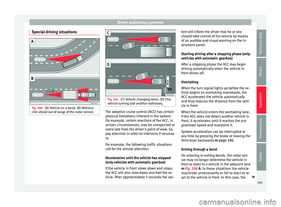
Special driving situations Fig. 200
(A) Vehicle on a bend. (B) Motorcy-
c li
s
t ahead out of range of the radar sensor. Fig. 201
(C) Vehicle changing lanes. (D) One
v ehic
l
e turning and another stationary. The adaptive cruise control (ACC) has certain
ph
y
s
ical limitations inherent in the system.
For example, certain reactions of the ACC, in
certain circumstances, may be unexpected or
come late from the driver's point of view. So
pay attention in order to intervene if necessa-
ry.
For example, the following traffic situations
call for the utmost attention:
Deceleration until the vehicle has stopped
(only vehicles with automatic gearbox)
If the vehicle in front slows down and stops,
the ACC will also slow down and halt the ve-
hicle. After approximately 3 seconds the sys- tem will inform the driver that he or she
should t
ake control of the vehicle by means
of an audible and visual warning on the in-
strument panel.
Starting driving after a stopping phase (only
vehicles with automatic gearbox)
After a stopping phase the ACC may begin
driving automatically when the vehicle in
front drives off.
Overtaking
When the turn signal lights up before the ve-
hicle begins an overtaking manoeuvre, the
ACC accelerates the vehicle automatically
and thus reduces the distance from the vehi-
cle in front.
When the vehicle enters the overtaking lane,
if the ACC does not detect another vehicle in
front, it accelerates until it reaches the pro-
grammed speed and maintains it.
System acceleration can be interrupted at
any time by pressing the brake or moving the
third lever backwards ››› page 190.
Driving through a bend
On entering or exiting bends, the radar sen-
sor may no longer determine the vehicle in
front or react to a vehicle in the adjacent lane
››› Fig. 200 A. In these situations the vehicle
may brake unnecessarily or fail to react to re-
act to the vehicle in front. In this case, the »
195
Technical data
Advice
Operation
Emergencies
Safety
Page 205 of 308
Driver assistance systems
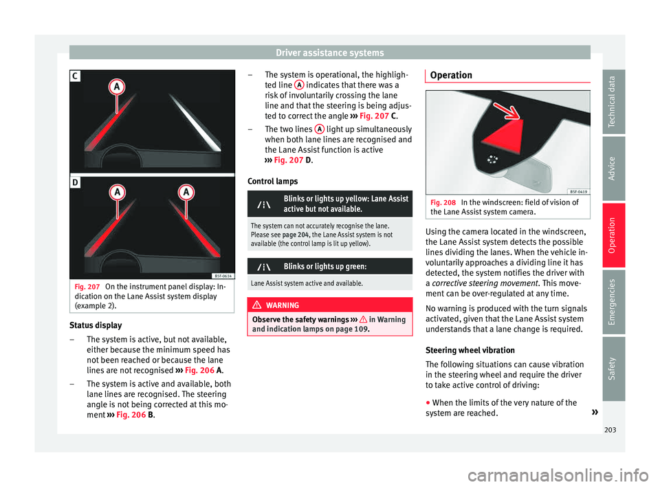
Fig. 207
On the instrument panel display: In-
dic ation on the Lane As
s
ist system display
(example 2). Status display
The sy s
t
em is active, but not available,
either because the minimum speed has
not been reached or because the lane
lines are not recognised ››› Fig. 206 A.
The system is active and available, both
lane lines are recognised. The steering
angle is not being corrected at this mo-
ment ››› Fig. 206 B.
–
– The system is operational, the highligh-
ted line
A indicates that there was a
ri sk
of
involuntarily crossing the lane
line and that the steering is being adjus-
ted to correct the angle ››› Fig. 207 C.
The two lines A light up simultaneously
when both l ane line
s
are recognised and
the Lane Assist function is active
››› Fig. 207 D.
Control lamps
Blinks or lights up yellow: Lane Assist
active but not available.
The system can not accurately recognise the lane.
Please see page 204, the Lane Assist system is not
available (the control lamp is lit up yellow).
Blinks or lights up green:
Lane Assist system active and available.
WARNING
Observe the safety warnings ›››
in Warning
and indication l amp
s on page 109. –
–
Operation Fig. 208
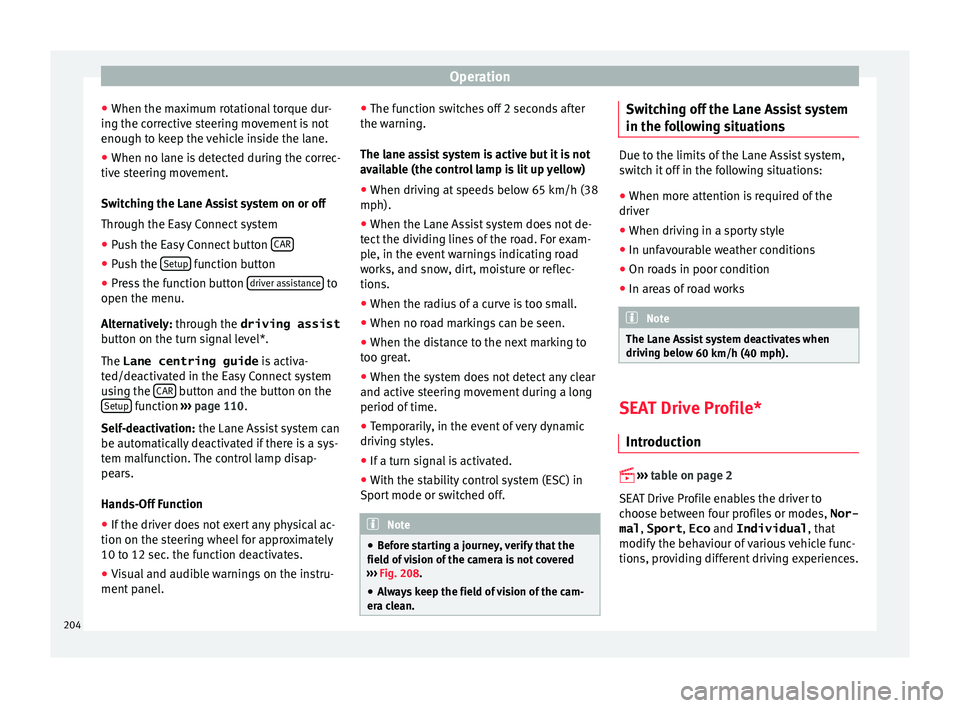
In the windscreen: field of vision of
the Lane As s
i
st system camera. Using the camera located in the windscreen,
the Lane As
s
i
st system detects the possible
lines dividing the lanes. When the vehicle in-
voluntarily approaches a dividing line it has
detected, the system notifies the driver with
a corrective steering movement . This move-
ment can be over-regulated at any time.
No warning is produced with the turn signals
activated, given that the Lane Assist system
understands that a lane change is required.
Steering wheel vibration
The following situations can cause vibration
in the steering wheel and require the driver
to take active control of driving:
● When the limits of the very nature of the
syst
em are reached. »
203
Technical data
Advice
Operation
Emergencies
Safety
Page 206 of 308
Operation
● When the m ax
imum r
otational torque dur-
ing the corrective steering movement is not
enough to keep the vehicle inside the lane.
● When no lane is detected during the correc-
tive st
eering movement.
Switching the Lane Assist system on or off
Through the Easy Connect system
● Push the Easy Connect button CAR●
Push the Set
up function button
● Press the function button driv
er a
s
sistance to
open the menu.
A lt
ern
atively: through the driving assist
button on the turn signal level*.
The Lane centring guide is activa-
ted/deactivated in the Easy Connect system
using the CAR button and the button on the
Set up function
››
› p
age 110.
Self-deactivation: the Lane Assist system can
be automatically deactivated if there is a sys-
tem malfunction. The control lamp disap-
pears.
Hands-Off Function
● If the driver does not exert any physical ac-
tion on the steerin
g wheel for approximately
10 to 12 sec. the function deactivates.
● Visual and audible warnings on the instru-
ment panel
. ●
The function sw
itches off 2 seconds after
the warning.
The lane assist system is active but it is not
available (the control lamp is lit up yellow)
● When driving at speeds below 65 km/h (38
mph).
● When the Lane Assist system does not de-
tect the div
iding lines of the road. For exam-
ple, in the event warnings indicating road
works, and snow, dirt, moisture or reflec-
tions.
● When the radius of a curve is too small.
● When no road markings can be seen.
● When the distance to the next marking to
too gre
at.
● When the system does not detect any clear
and active st
eering movement during a long
period of time.
● Temporarily, in the event of very dynamic
driving s
tyles.
● If a turn signal is activated.
● With the stability control system (ESC) in
Sport
mode or switched off. Note
● Bef or
e starting a journey, verify that the
field of vision of the camera is not covered
››› Fig. 208.
● Always keep the field of vision of the cam-
era cl
ean. Switching off the Lane Assist system
in the f
o
l
lowing situations Due to the limits of the Lane Assist system,
swit
c
h it off in the following situations:
● When more attention is required of the
driver
● When drivin
g in a sporty style
● In unfavourable weather conditions
● On roads in poor condition
● In areas of road works Note
The Lane Assist system deactivates when
drivin g belo
w 60 km/h (40 mph). SEAT Drive Profile*
Intr oduction
›› ›
table on page 2
SEAT Drive Profile enables the driver to
choose between four profiles or modes, Nor-
mal , Sport , Eco and Individual , that
modify the behaviour of various vehicle func-
tions, providing different driving experiences.
204
Page 216 of 308
Operation
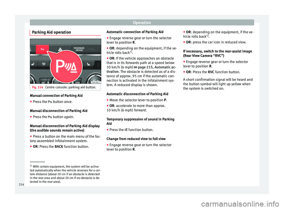
Parking Aid operation Fig. 214
Centre console: parking aid button. Manual connection of Parking Aid
● Press the butt
on once.
Manual disconnection of Parking Aid
● Press the button
again.
Manual disconnection of Parking Aid display
(the audible sounds remain active)
● Press a button on the main menu of the fac-
tory
-assembled infotainment system.
● OR: Press the BACK fu
nction button. Automatic connection of Parking Aid
● Engage reverse gear or turn the selector
lever t
o position R.
● OR: depending on the equipment, if the
ve-
hicle rolls back 1)
.
● OR: If the vehicle approaches an obstacle
that
is in its forwards path at a speed below
10 km/h (6 mph) ››› page 215, Automatic ac-
tivation. The obstacle is detected as of a dis-
tance of approx. 95 cm if the automatic con-
nection is activated in the infotainment sys-
tem. A reduced display is shown.
Automatic disconnection of Parking Aid
● Move the selector lever to position P.
● OR: accelerate to more than approx.
10 km/h (6 mph) for
ward.
Temporary suppression of sound in Parking
Aid
● Press the function b
utton.
Change from reduced view to full view
● Engage reverse gear or turn the selector
lever t
o position R. ●
OR: depending on the equipment, if the
ve-
hicle rolls back 1)
.
● OR: press the car icon in reduced view.
If nec
essary, switch to the rear-assist image
(Rear View Camera “RVC”)
● Engage reverse gear or turn the selector
lever t
o position R.
● OR: Press the RVC fu
nction button.
A short confirmation signal will be heard and
the button symbol will light up yellow when
the system is switched on. 1)
With certain equipment, the system will be activa-
ted aut om
atically when the vehicle reverses for a cer-
tain distance (about 10 cm if an obstacle is detected
in the rear area and about 20 cm if no obstacle is de-
tected in the rear area).
214
Page 218 of 308
Operation
Moreover, with the SEAT Media System
Plu s/Nav
i
System radios, a yellow trail indi-
cates the vehicle's expected journey based
on the steering wheel angle.
Whenever the obstacle is located in the vehi-
cle’s direction of travel, the corresponding
audible warning will sound.
As the vehicle approaches an obstacle, the
segments are displayed closer to the vehicle.
When the penultimate segment is displayed,
this means that the vehicle has reached the
collision zone. In the collision zone, the ob-
stacles are represented in red, including
those out of the path. Do not continue to
move forward (or backward) ››› in General
inf orm
ation on p
age 212, ››› in General in-
f orm
ation on p
age 212 !
Adjusting the display and audible
warning
s The settings for the display and audible
w
arnin
g
s are controlled via the Easy Con-
nect*.
Automatic activation
on – activates the Automatic activa-
tion option ›››
page 215.
off – deactivates the Automatic ac-
tivation option ››› page 215. Front volume*
Volume in the fr
ont and rear area.
Front sound settings/sharpness*
Frequency (tone) of the sound in the front
area.
Rear volume*
Volume in the rear area.
Rear sound settings/sharpness*
Frequency (tone) of the sound in the rear
area.
Adjust volume
With the parking aid switched on, the active
audio/video source volume will be reduced
to the intensity of the selected setting.
Error messages When the Parking Aid is activated or when it
i
s
sw
itched on, if a message reporting a Park-
ing aid error is displayed on the instrument
panel, there is a fault in the system.
If the fault doesn't disappear before discon-
necting the ignition, next time that parking
aid is engaged in reverse, it will not be indi-
cated. Parking System Plus*
If there i
s a fault in the parking aid system a
message will appear on the instrument panel
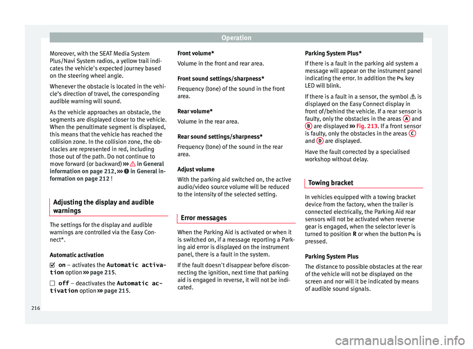
indicating the error. In addition the key
LED will blink.
If there is a fault in a sensor, the symbol is
displayed on the Easy Connect display in
front of/behind the vehicle. If a rear sensor is
faulty, only the obstacles in the areas A and
B are displayed
››
›
Fig. 213. If a front sensor
is faulty, only the obstacles in the areas C and
D are displayed.
Hav e the f
au
lt corrected by a specialised
workshop without delay.
Towing bracket In vehicles equipped with a towing bracket
dev
ic
e fr
om the factory, when the trailer is
connected electrically, the Parking Aid rear
sensors will not be activated when reverse
gear is engaged, when the selector lever is
turned to position R or when the button is
pressed.
Parking System Plus
The distance to possible obstacles at the rear
of the vehicle will not be displayed on the
screen and nor will it be indicated by means
of audible sound signals.
216
Page 228 of 308
Operation
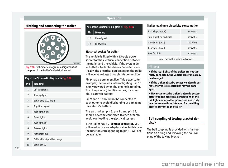
Hitching and connecting the trailer Fig. 230
Schematic diagram: assignment of
the pins of the trailer's electrical socket.
Key of the Schematic diagram ››› Fig. 230:
PinMeaning
1Left turn signal
2Rear fog light
3Earth, pins 1, 2, 4 to 8
4Right turn signal
5Rear light, right
6Brake lights
7Rear light, left
8Reverse lights
9Permanent live
10Cable without positive charge
11Earth, pin 10
Key of the Schematic diagram ››› Fig. 230:
PinMeaning
12Unassigned
13Earth, pin 9 Electrical socket for trailer
The v
ehic
le is fitted with a 13-pole power
socket for the electrical connection between
the trailer and the vehicle. If the system de-
tects that a trailer has been connected elec-
trically, the electrical equipment on the trailer
will receive voltage through this connection.
Pin 9 has a permanent live. This powers, for
example, the trailer's interior lighting. Pin 10
is only powered when the engine is running.
The charge wire (pin 10) charges, for exam-
ple, a caravan battery.
Pin 9 and 10 should not be connected to
each other to avoid discharging or damaging
the vehicle's battery.
The earth wires, pin 3, pin 11 and pin 13,
should never be connected to each other to
avoid overloading the electrical system.
If the trailer has a 7-contact connector , you
will need to use an adapter cable. In this case
the function corresponding to pin 10 will not
be available. Trailer maximum electricity consumption
Brake lights (total)84 Watts
Turn signal, on each side42 Watts
Side lights (total)100 Watts
Rear lights (total)42 Watts
Rear fog light42 Watts
Never exceed the values indicated!
Note
● If the r e
ar lights of the trailer are not cor-
rectly connected, the vehicle electronics may
be damaged.
● If the trailer absorbs excessive electric cur-
rent, the v
ehicle electronics may be dam-
aged.
● Never connect the trailer's electric system
directly t
o the electrical connections of the
tail lights or any other power sources. Only
use the connections intended for providing
electric current to the trailer. Ball coupling of towing bracket de-
v
ic
e* The ball coupling is provided with instruc-
tion
s
on fittin
g and removing the ball cou-
pling of the towing bracket.
226
Page 296 of 308
Index
Blown bulbs ch
an
ging a bulb . . . . . . . . . . . . . . . . . . . . . . . . . 94
Bonnet . . . . . . . . . . . . . . . . . . . . . . . . . . . . . 13, 246 opening the bonnet . . . . . . . . . . . . . . . . . . . . . 247
Brake assist system . . . . . . . . . . . . . . . . . . . . . . . 178
Brake fluid . . . . . . . . . . . . . . . . . . . . . . . . . . . . . . . 53
Brakes . . . . . . . . . . . . . . . . . . . . . . . . . . . . . . . . . . 181 brake fluid . . . . . . . . . . . . . . . . . . . . . . . . . . . . . 251
Brake servo . . . . . . . . . . . . . . . . . . . . . . . . . . . . 181
new brake pads . . . . . . . . . . . . . . . . . . . . . . . . 181
Braking Brake assist system . . . . . . . . . . . . . . . . . . . . . 178
Moving off on hills . . . . . . . . . . . . . . . . . . . . . . 182
C Camera cleaning . . . . . . . . . . . . . . . . . . . . . . . . . . . . . . 233
cleanliness . . . . . . . . . . . . . . . . . . . . . . . . . . . . 208
Lane Assist . . . . . . . . . . . . . . . . . . . . . . . . . . . . 203
Capacities . . . . . . . . . . . . . . . . . . . . . . . . . . . . . . . . 51 fuel tank . . . . . . . . . . . . . . . . . . . . . . . . . . . . . . 108
natural gas tank . . . . . . . . . . . . . . . . . . . . . . . . 242
windscreen washer water . . . . . . . . . . . . . . . . 252
Car-care products . . . . . . . . . . . . . . . . . . . . . . . . . 231
Catalytic converter . . . . . . . . . . . . . . . . . . . . . . . . 176
CCS . . . . . . . . . . . . . . . . . . . . . . . . . . . . . . . . . . . . . 40
CD-ROM player (navigation) . . . . . . . . . . . . . . . . 146
Central locking system . . . . . . . . . . . . . . . . . . . . . 116 anti-theft alarm . . . . . . . . . . . . . . . . . . . . . . . . . 121
central locking switch . . . . . . . . . . . . . . . . . . . . 119
Electric windows . . . . . . . . . . . . . . . . . . . . . . . . 125
manual locking . . . . . . . . . . . . . . . . . . . . . . . . . . 12
programming . . . . . . . . . . . . . . . . . . . . . . . . . . 119
remote control key . . . . . . . . . . . . . . . . . . . . . . 118
selective unlocking system . . . . . . . . . . . . . . . 118
sliding/tilting sunroof . . . . . . . . . . . . . . . . . . . 125
Cetane number (diesel fuel) . . . . . . . . . . . . . . . . 244 Changing
parts . . . . . . . . . . . . . . . . . . . . . . . . . . . . . . . . . 230
Changing a bulb . . . . . . . . . . . . . . . . . . . . . . . . . . . 94 front fog light bulbs . . . . . . . . . . . . . . . . . . . . . . 96
number plate light . . . . . . . . . . . . . . . . . . . . . . 100
rear light bulb on the rear lid . . . . . . . . . . . . . . . 99
rear light bulbs on the side panel . . . . . . . . . . . 97
Rear light on the side panel . . . . . . . . . . . . . . . . 98
Changing a wheel . . . . . . . . . . . . . . . . . . . . . . . . . 58 subsequent work . . . . . . . . . . . . . . . . . . . . . . . . 60
Changing gear engaging gears (manual gearbox) . . . . . . . . . 167
Changing main headlight bulbs turn signal . . . . . . . . . . . . . . . . . . . . . . . . . . . . . . 95
Changing settings CAR menu . . . . . . . . . . . . . . . . . . . . . . . . . . . . . . 28
Changing the blades . . . . . . . . . . . . . . . . . . . . . . . 88
Changing the main beam headlight bulb main beam headlight . . . . . . . . . . . . . . . . . . . . . 96
Changing the main headlight bulb day light . . . . . . . . . . . . . . . . . . . . . . . . . . . . . . . 95
dipped headlight . . . . . . . . . . . . . . . . . . . . . . . . 95
Changing the wiper blades . . . . . . . . . . . . . . . . . . 64
Charging the battery . . . . . . . . . . . . . . . . . . . . . . 254
Checking levels engine compartment . . . . . . . . . . . . . . . . . . . . 246
Child-proof locking electric windows . . . . . . . . . . . . . . . . . . . . . . . . 124
Child seats . . . . . . . . . . . . . . . . . . . . . . . . . . . . 20, 85 categorisation in groups . . . . . . . . . . . . . . . . . . 85
ISOFIX system . . . . . . . . . . . . . . . . . . . . . . . . . . . 22
safety instructions . . . . . . . . . . . . . . . . . . . . 20, 84
Securing with seat belt . . . . . . . . . . . . . . . . . . . 21Top Tether system . . . . . . . . . . . . . . . . . . . . . 22, 24
City Emergency braking function . . . . . . . . . . . . . 201 Cleaning . . . . . . . . . . . . . . . . . . . . . . . . . . . . . . . . 231
alcantar a . . . . . . . . . . . . . . . . . . . . . . . . . . . . . . 237
carbon parts . . . . . . . . . . . . . . . . . . . . . . . . . . . 234
Easy Connect control panel . . . . . . . . . . . . . . . 235
Exhaust pipe . . . . . . . . . . . . . . . . . . . . . . . . . . . 234
Fabrics . . . . . . . . . . . . . . . . . . . . . . . . . . . . . . . . 235
Leather . . . . . . . . . . . . . . . . . . . . . . . . . . . . . . . 236
natural leather . . . . . . . . . . . . . . . . . . . . . . . . . 236
plastic parts . . . . . . . . . . . . . . . . . . . . . . 233, 235
Radio display . . . . . . . . . . . . . . . . . . . . . . . . . . 235
seat belts . . . . . . . . . . . . . . . . . . . . . . . . . . . . . 237
trims . . . . . . . . . . . . . . . . . . . . . . . . . . . . . . . . . 233
washing the vehicle . . . . . . . . . . . . . . . . . . . . . 231
wheels . . . . . . . . . . . . . . . . . . . . . . . . . . . . . . . . 234
windows . . . . . . . . . . . . . . . . . . . . . . . . . . . . . . 234
Climatronic . . . . . . . . . . . . . . . . . . . . . . . . . . . . . . . 45
Closing . . . . . . . . . . . . . . . . . . . . . . . . . . . . . . . . . 116 bonnet . . . . . . . . . . . . . . . . . . . . . . . . . . . . . . . . 247
Panoramic sliding sunroof . . . . . . . . . . . . . . . . 126
windows . . . . . . . . . . . . . . . . . . . . . . . . . . . . . . 124
Clutch (warning lamp) . . . . . . . . . . . . . . . . . . . . . 174
Coming Home . . . . . . . . . . . . . . . . . . . . . . . . . . . . 132
Controls and displays general instrument panel . . . . . . . . . . . . . . . . . 103
Controls on the steering wheel Operating the audio system . . . . . . . . . . . . . . 112
operating the audio system and telephone . . 113
Convenience closing panoramic sliding sunroof . . . . . . . . . . . . . . . . 127
Convenience opening panoramic sliding sunroof . . . . . . . . . . . . . . . . 127
Coolant checking level . . . . . . . . . . . . . . . . . . . . . . . . . . 250
Cooling system checking coolant . . . . . . . . . . . . . . . . . . . . . . . 250
Coolant temperature gauge . . . . . . . . . . . . . . . 107
topping up coolant . . . . . . . . . . . . . . . . . . . . . . 250
294