key battery Seat Leon SC 2015 Owner's manual
[x] Cancel search | Manufacturer: SEAT, Model Year: 2015, Model line: Leon SC, Model: Seat Leon SC 2015Pages: 308, PDF Size: 5.93 MB
Page 119 of 308
Opening and closing
Note
● Never l e
ave any valuable items in the vehi-
cle unattended. Even a locked vehicle is not a
safe.
● If the diode on the driver door sill lights up
for about 30 sec
onds when the vehicle is
locked, the central locking system or anti-
theft alarm* is not working properly. You
should have the fault repaired at a SEAT Offi-
cial Service or specialised workshop.
● The vehicle interior monitoring of the anti-
theft a
larm* system will only function as in-
tended if the windows and the sunroof* are
closed. Car key
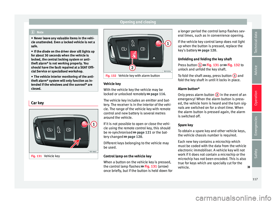
Fig. 131
Vehicle key Fig. 132
Vehicle key with alarm button Vehicle key
W
ith the
v
ehicle key the vehicle may be
locked or unlocked remotely ››› page 116.
The vehicle key includes an emitter and bat-
tery. The receiver is in the interior of the vehi-
cle. The range of the vehicle key with remote
control and new battery is several metres around the vehicle.
If it is not possible to open or close the vehi-
cle using the remote control key, this should
be re-synchronised ››› page 121 or the bat-
tery changed ››› page 120.
Different keys belonging to the vehicle may
be used.
Control lamp on the vehicle key
When a button on the vehicle key is pressed,
the control lamp flashes ››› Fig. 131 (arrow)
once briefly, but if the button is held down for a longer period the control lamp flashes sev-
eral time
s, such as in convenience opening.
If the vehicle key control lamp does not light
up when the button is pressed, replace the
key's battery ››› page 120.
Unfolding and folding the key shaft
Press button 1
› ››
Fig. 131
or ›
›› Fig. 132 to
unlock and unfold the key shaft.
To fold the shaft away, press button 1 and
f o
l
d the key shaft in until it locks in place.
Alarm button*
Only press alarm button 2 in the event of an
emer g
ency!
When the alarm button is press-
ed, the vehicle horn is heard and the turn sig-
nals are switched on for a short time. When
the alarm button is pressed again, the alarm
is switched off.
Spare key
To obtain a spare key and other vehicle keys,
the vehicle chassis number is required.
Each new key contains a microchip which
must be coded with the data from the vehicle
electronic immobiliser. A vehicle key will not
work if it does not contain a microchip or the
microchip has not been encoded. This is also
true for keys which are specially cut for the
vehicle. »
117
Technical data
Advice
Operation
Emergencies
Safety
Page 122 of 308
Operation
Please see Instruction Manual . The
v ehic
le cannot be opened from inside. This
makes it more difficult for unauthorised per-
sons to break into the vehicle ››› in De-
s c
ription on p
age 116.
The anti-theft security system can be switch-
ed off each time the vehicle is locked:
● Turn the key a second time to the lock posi-
tion, in the door lock, f
or the next two sec-
onds. If necessary, remove the protective cov-
er on the driver door handle ›››
page 11
or else
● Press on the remote control key for a
sec ond time
f
or the following 2 seconds.
The flashing frequency of the diode in the
door sill immediately confirms the process.
Initially, the diode flashes in a fast sequence
for a brief period, then it stops for approxi-
mately 30 seconds and, lastly continues
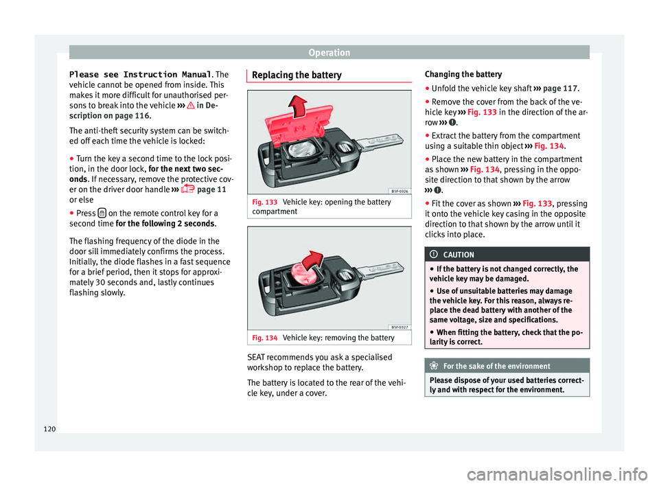
flashing slowly. Replacing the battery Fig. 133
Vehicle key: opening the battery
c omp
ar
tment Fig. 134
Vehicle key: removing the battery SEAT recommends you ask a specialised
w
ork
shop t
o replace the battery.
The battery is located to the rear of the vehi-
cle key, under a cover. Changing the battery
● Unfold the vehicle key shaft ›››
page 117.
● Remove the cover from the back of the ve-
hicle k
ey ››› Fig. 133 in the direction of the ar-
row ››› .
● Extract the battery from the compartment
u s
in
g a suitable thin object ››› Fig. 134.
● Place the new battery in the compartment
as sho
wn ››› Fig. 134, pressing in the oppo-
site direction to that shown by the arrow
››› .
● Fit the cover as shown ››
›
Fig. 133 , pressing
it onto the vehicle key casing in the opposite
direction to that shown by the arrow until it
clicks into place. CAUTION
● If the b att
ery is not changed correctly, the
vehicle key may be damaged.
● Use of unsuitable batteries may damage
the vehic
le key. For this reason, always re-
place the dead battery with another of the
same voltage, size and specifications.
● When fitting the battery, check that the po-
larity i
s correct. For the sake of the environment
Please dispose of your used batteries correct-
ly and w ith r
espect for the environment.120
Page 124 of 308
Operation
alarm is activated immediately on opening
the door).
● A door is opened.
● The bonnet is opened.
● The rear lid is opened.
● When the ignition is switched on with a
non- authori
sed k
ey.
● When the vehicle battery is disconnected.
● Movement inside the vehicle (in vehicles
with interior monit
oring ››› page 123).
● When the vehicle is towed (in vehicles with
anti-tow sy
stem ››› page 123).
● When the vehicle is raised (in vehicles with
anti-tow sy
stem ››› page 123).
● When the vehicle is transported on a ferry
or by r
ail (vehicles with an anti-tow system or
vehicle interior monitoring ››› page 123).
● When a trailer connected to the anti-theft
alarm sys
tem is disconnected.
How to turn OFF the alarm
Unlock the vehicle with the unlocking button
on the key or turn on the ignition with a valid
key. Note
● Aft er 28 d
ays, the indicator light will be
switched off to prevent the battery from ex-
hausting if the vehicle has been left parked for a long period of time. The alarm system
rem
ain
s activated.
● If, after the audible warning goes off, an-
other monitored ar
ea is accessed (e.g. the
rear lid is opened after a door has been
opened), the alarm is triggered again.
● The anti-theft alarm is not activated when
the vehic
le is locked from within using the
central locking button .
● If the driver door is unlocked mechanically
with the k ey
, only the driver door is unlocked,
the rest of the doors remain locked. Only
when the ignition has been turned on will the
other doors be available - but not unlocked -
and the central lock button will be activated.
● If the vehicle battery is run down or flat
then the anti-theft a
larm will not operate cor-
rectly.
● Vehicle monitoring remains active even if
the batter
y is disconnected or not working for
any reason.
● The alarm is triggered immediately if one of
the batter
y cables is disconnected while the
alarm system is active. Vehicle interior monitoring and anti-
t
o
w sy
stem* It is a monitoring or control function incorpo-
r
at ed in the anti-thef
t alarm* which detects
unauthorised vehicle entry by means of ultra-
sound. Activation
– It is automatically switched on when the
anti-theft al
arm is activated.
Deactivation – Open the vehicle with the key, either me-
chanic
ally or by pressing the button on
the r emot
e c
ontrol. The time period from
when the door is opened until the key is in-
serted in the contact should not exceed 15
seconds, otherwise the alarm will be trig-
gered.
– Press the button on the remote control
tw ic
e.
The volumetric sensor and tilt sen-
sors will be deactivated. The alarm system
remains activated.
The vehicle interior monitoring and the anti-
tow system are automatically switched on
again next time the vehicle is locked.
The vehicle interior monitoring and anti-tow
sensor (tilt sensor) are automatically switch-
ed on when the anti-theft alarm is switched
on. In order to activate it, all the doors and
the rear lid must be closed.
If you wish to switch off the vehicle interior
monitoring and the anti-tow system, it must
be done each time that the vehicle is locked;
if not, they will be automatically switched on.
The vehicle interior monitoring and the anti-
tow system should be switched off if animals
are left inside the locked vehicle (otherwise,
122
Page 128 of 308
Operation
– Fir s
t
unlock the vehicle using button on
the r emot
e c
ontrol key and then keep the
key in the driver door lock until all the win-
dows and the sliding/tilting sunroof* have
reached the required position.
Convenience close function
– Press and hold button on the remote
c ontr
o
l key until all the windows and the
sliding/tilting sunroof* are closed ››› , or
– Keep the key in the driver door in the "lock"
po s
ition u
ntil all the windows and the slid-
ing/tilting sunroof* are closed.
Programming convenience opening in the
Easy Connect*
– Select: function button CAR > control but-
t on Vehicle systems
* > Car settings
> Central locking > Open the win-
dow by holding button down or el
se
>
Front window on/off or else Roof
on/off *. WARNING
● Tak e c
are when closing the sliding/tilting
sunroof* and windows. There is a risk of suf-
fering injury.
● For safety reasons, you should only use the
remote c
ontrol open and close functions with-
in about 2 metres of the vehicle. To avoid in-
juries, always keep an eye on the windows
and the sliding/tilting sunroof* when press- ing the button to close them. The windows
st
op mo
ving as soon as the button is re-
leased. One-touch opening and closing*
One-touch opening and closing means you
do not h
av
e to hold down the button.
Buttons ››› Fig. 137 1 ,
2 ,
3 and
4 have
two po s
itions for opening windows and two
for closing them. This makes it easier to open
and close windows to the desired position.
One-touch closing
– Pull up the window button briefly up to the
second po s
ition. The window closes fully.
One-touch opening
– Push down the window button briefly up to
the second pos
ition. The window opens
fully.
Restoring one-touch opening and closing
The automatic open and close function will
not work if the battery has been temporarily
disconnected. The function can be restored
as follows:
– Close the window as far as it will go by lift-
ing and hol
ding the electric window switch. –
Rele
ase the switch and then lift it again for
1 second. This will re-enable the automatic
function.
If you push (or pull) a button to the first
stage, the window will open (or close) until
you release the button. If you push or lift the
button briefly to the second stage, the win-
dow will open (one-touch opening) or close
(one-touch closing) automatically. If you op-
erate the button while the window is opening
or closing, it stops at this position.
Panoramic sliding sunroof*
Opening or clo
sing the panoramic
sliding sunroof Read the additional information carefully
› ›
›
page 14
The panoramic sliding sunroof will only work
with the ignition on. It can be opened or
closed for a few minutes after the ignition
has been switched off, provided the driver
door and the front passenger door are not
opened. WARNING
Careless or uncontrolled use of the panoram-
ic s lidin
g sunroof can cause serious injuries.126
Page 137 of 308
Lights and visibility
Dynamic headlight range control
The c ontr
o
l is not mounted in vehicles with
dynamic headlight range control. The head-
light range is automatically adjusted accord-
ing to the vehicle load status when they are
switched on.
Instrument panel lighting
With the ignition on and without light activa-
tion, the instrument panel lighting remains
activated in daytime light conditions. The
lighting is reduced as the exterior light di-
minishes. In some cases, e.g. when driving
through a tunnel without the function
active, the instrument panel lighting may
even switch off. The objective of this function
is to provide the driver with a visual indica-
tion that he or she should activate the dip-
ped beam. WARNING
Heavy objects in the vehicle may mean that
the hea dlight
s dazzle and distract other driv-
ers. This could result in a serious accident.
● Adjust the light beam to the vehicle load
stat
us so that it does not blind other drivers. Interior and reading lights
1)
›› ›
table on page 2
Read the additional information carefully
››› page 26
Glove compartment and luggage compart-
ment lighting*
When opening and closing the glove com-
partment on the front passenger side and the
rear lid, the respective light will automatically
switch on and off.
Footwell lighting*
The lights in the footwell area below the dash
(driver and front passenger sides) will switch
on when the doors are opened and will de-
crease in intensity while driving. The intensity
of these lights can be adjusted using the ra-
dio menu (see Easy Connect > Adjust-
ing Lighting > Interior lighting
››› page 28).
Ambient light*
The ambient light in the door panel changes
colour (white or red) depending on the driv-
ing mode. The intensity of these lights can be adjusted using the radio menu (see Easy
Connect > Adjusting Lights > In-
terior lighting › ›
›
page 28). Note
The reading lights switch off when the vehi-
cl e i
s locked using a key or after several mi-
nutes if the key is removed from the ignition.
This prevents the battery from discharging. Visibility
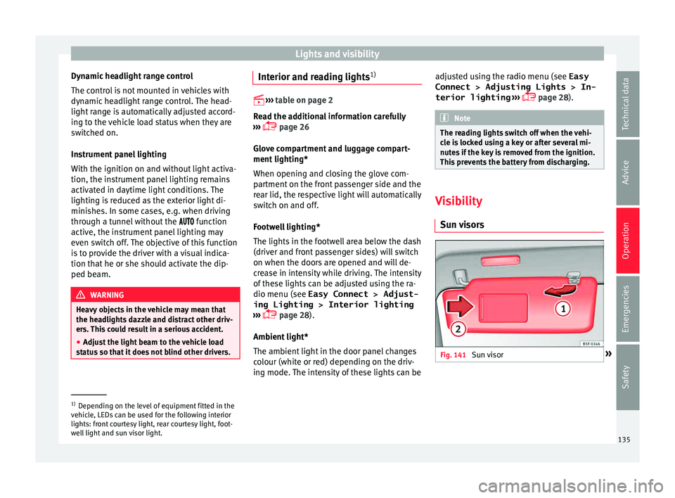
Su n
visors Fig. 141
Sun visor »1)
Depending on the level of equipment fitted in the
vehic l
e, LEDs can be used for the following interior
lights: front courtesy light, rear courtesy light, foot-
well light and sun visor light. 135
Technical data
Advice
Operation
Emergencies
Safety
Page 167 of 308
Driving
WARNING
● Never ru n the en
gine in confined spaces, as
the exhaust gases are poisonous. CAUTION
Avoid high engine speeds, full throttle and
extr eme lo
ad conditions until the engine has
reached its normal operating temperature,
otherwise this can damage the engine. For the sake of the environment
Do not warm up the engine by idling it. You
shoul d driv
e off as soon as you start the en-
gine. This will help avoid unnecessary ex-
haust emissions. Note
● If it i
s difficult to turn the ignition key to
the position 1 , turn the steering wheel to
both side s
to release the steering lock.
● When starting from cold, the engine may be
a little noisy
for the first few seconds until oil
pressure has built up in the hydraulic valve
lifters. This is quite normal, and no cause for
concern.
● If the vehicle battery is disconnected and
reconnect
ed, the key must remain in the posi-
tion 1 for around 5 seconds before starting
up.
● Vehic
les with automatic gearbox: after
switc
hing off the ignition, you can only re-
move the ignition key if the selector lever is in position “P” (parking lock). Next, the se-
lect
or l
ever is locked. Switching off the engine with the key
Switching off the engine
– Stop the vehicle.
– Turn the ignition key to position 1 ›››
Fig. 185.
Eng agin
g the steering wheel lock
In vehicles with automatic gearbox, the igni-
tion key can only be removed when the selec-
tor lever is in position P.
– Remove the key from the ignition in posi-
tion 1
› ›
› Fig. 185
››› .
– Turn the steering wheel until you hear it en-
gag
e.
P
ossible vehicle theft is prevented with the
steering lock engaged. WARNING
● Never sw it
ch the engine off until the vehi-
cle is stationary. The brake servo and power
steering functions will not be completely cov-
ered under warranty. More force may also be
needed to turn the steering wheel or to brake.
As you cannot steer and brake in the normal
manner, there is a greater risk of accidents
and serious injury. ●
Never r emo
ve the key from the ignition if
the vehicle is in motion. Otherwise, the steer-
ing could suddenly lock, making it impossible
to steer the vehicle: risk of accident!
● Always take the key with you when you
leav
e the vehicle. This is particularly impor-
tant if there are children in the vehicle, as
they might otherwise be able to start the en-
gine or use power-operated equipment (e.g.
the electric windows), which could cause in-
juries. CAUTION
If the engine has been running under high
loa d f
or a long time, there is a risk of heat
building up in the engine compartment after
it has been switched off; this could cause en-
gine damage. For this reason, you should idle
the engine for approximately 2 minutes be-
fore you switch it off. Note
● Aft er the en
gine is switched off the radiator
fan may run on for up to 10 minutes, even if
the ignition is switched off. It is also possible
that the fan turns itself on once more if the
coolant temperature increases due to the
heat accumulated in the engine compartment
or due to its prolonged exposure to solar ra-
diation.
● If the vehicle is stopped and the Start-Stop
syst
em* switches off the engine, the ignition » 165
Technical data
Advice
Operation
Emergencies
Safety
Page 168 of 308
Operation
remains switched on. Make sure that the igni-
tion is
sw
itched off before leaving the
vehicle, otherwise the battery could dis-
charge. Braking and parking
Us in
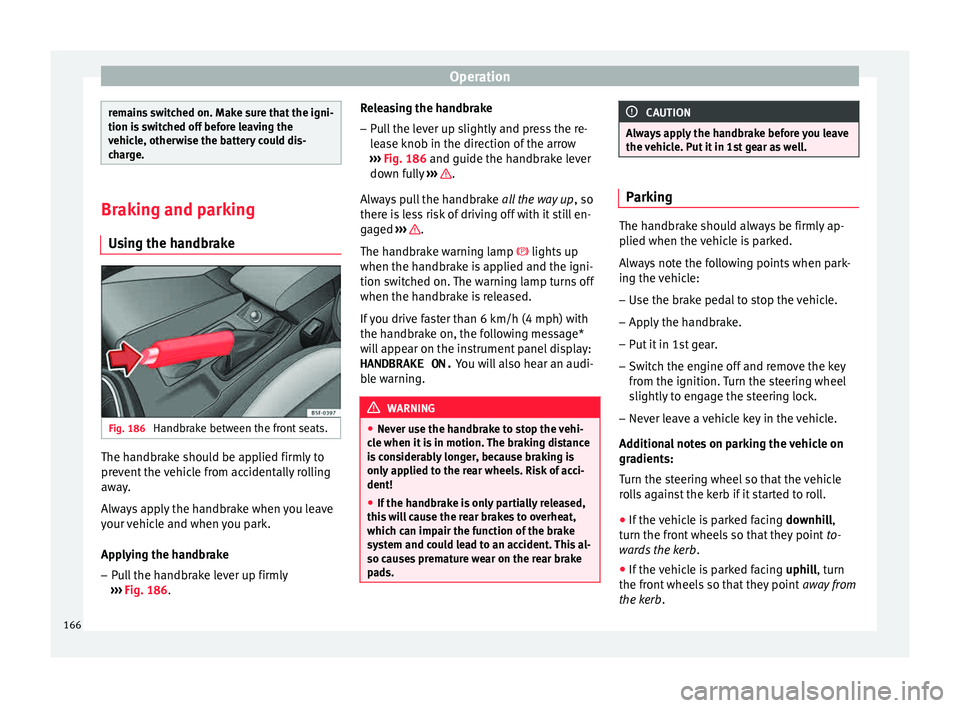
g the handbrake Fig. 186
Handbrake between the front seats. The handbrake should be applied firmly to
pr
ev
ent
the vehicle from accidentally rolling
away.
Always apply the handbrake when you leave
your vehicle and when you park.
Applying the handbrake
– Pull the handbrake lever up firmly
›››
Fig. 186. Releasing the handbrake
– Pull the lever up slightly and press the re-
lea
se knob in the direction of the arrow
››› Fig. 186 and guide the handbrake lever
down fully ››› .
A lw
a
ys pull the handbrake all the way up, so
there is less risk of driving off with it still en-
gaged ››› .
The h andbr
ak
e warning lamp lights up
when the handbrake is applied and the igni-
tion switched on. The warning lamp turns off
when the handbrake is released.
If you drive faster than 6 km/h (4 mph) with
the handbrake on, the following message*
will appear on the instrument panel display: HANDBRAKE ON. You will also hear an audi-
ble warning. WARNING
● Never u se the h
andbrake to stop the vehi-
cle when it is in motion. The braking distance
is considerably longer, because braking is
only applied to the rear wheels. Risk of acci-
dent!
● If the handbrake is only partially released,
this w
ill cause the rear brakes to overheat,
which can impair the function of the brake
system and could lead to an accident. This al-
so causes premature wear on the rear brake
pads. CAUTION
Always apply the handbrake before you leave
the v ehic
le. Put it in 1st gear as well. Parking
The handbrake should always be firmly ap-
plied when the
v
ehicle is parked.
Always note the following points when park-
ing the vehicle: – Use the brake pedal to stop the vehicle.
– Apply the handbrake.
– Put it in 1st gear.
– Switch the engine off and remove the key
from the ignition. T
urn the steering wheel
slightly to engage the steering lock.
– Never leave a vehicle key in the vehicle.
Additiona
l notes on parking the vehicle on
gradients:
Turn the steering wheel so that the vehicle
rolls against the kerb if it started to roll.
● If the vehicle is parked facing downhil
l,
turn the front wheels so that they point to-
wards the kerb .
● If the vehicle is parked facing uphill
, turn
the front wheels so that they point away from
the kerb.
166
Page 228 of 308
Operation
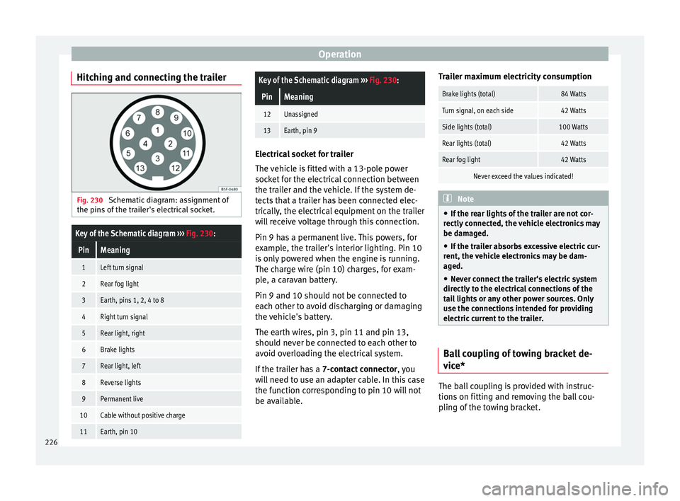
Hitching and connecting the trailer Fig. 230
Schematic diagram: assignment of
the pins of the trailer's electrical socket.
Key of the Schematic diagram ››› Fig. 230:
PinMeaning
1Left turn signal
2Rear fog light
3Earth, pins 1, 2, 4 to 8
4Right turn signal
5Rear light, right
6Brake lights
7Rear light, left
8Reverse lights
9Permanent live
10Cable without positive charge
11Earth, pin 10
Key of the Schematic diagram ››› Fig. 230:
PinMeaning
12Unassigned
13Earth, pin 9 Electrical socket for trailer
The v
ehic
le is fitted with a 13-pole power
socket for the electrical connection between
the trailer and the vehicle. If the system de-
tects that a trailer has been connected elec-
trically, the electrical equipment on the trailer
will receive voltage through this connection.
Pin 9 has a permanent live. This powers, for
example, the trailer's interior lighting. Pin 10
is only powered when the engine is running.
The charge wire (pin 10) charges, for exam-
ple, a caravan battery.
Pin 9 and 10 should not be connected to
each other to avoid discharging or damaging
the vehicle's battery.
The earth wires, pin 3, pin 11 and pin 13,
should never be connected to each other to
avoid overloading the electrical system.
If the trailer has a 7-contact connector , you
will need to use an adapter cable. In this case
the function corresponding to pin 10 will not
be available. Trailer maximum electricity consumption
Brake lights (total)84 Watts
Turn signal, on each side42 Watts
Side lights (total)100 Watts
Rear lights (total)42 Watts
Rear fog light42 Watts
Never exceed the values indicated!
Note
● If the r e
ar lights of the trailer are not cor-
rectly connected, the vehicle electronics may
be damaged.
● If the trailer absorbs excessive electric cur-
rent, the v
ehicle electronics may be dam-
aged.
● Never connect the trailer's electric system
directly t
o the electrical connections of the
tail lights or any other power sources. Only
use the connections intended for providing
electric current to the trailer. Ball coupling of towing bracket de-
v
ic
e* The ball coupling is provided with instruc-
tion
s
on fittin
g and removing the ball cou-
pling of the towing bracket.
226
Page 248 of 308
Advice
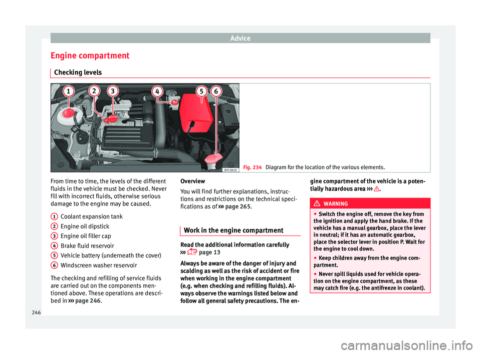
Engine compartment Chec k
in
g levels Fig. 234
Diagram for the location of the various elements. From time to time, the levels of the different
fluid
s
in the
vehicle must be checked. Never
fill with incorrect fluids, otherwise serious
damage to the engine may be caused.
Coolant expansion tank
Engine oil dipstick
Engine oil filler cap
Brake fluid reservoir
Vehicle battery (underneath the cover)
Windscreen washer reservoir
The checking and refilling of service fluids
are carried out on the components men-
tioned above. These operations are descri-
bed in ››› page 246.
1 2
3
4
5
6 Overview
Y
ou w
i
ll find further explanations, instruc-
tions and restrictions on the technical speci-
fications as of ››› page 265.
Work in the engine compartment Read the additional information carefully
›› ›
page 13
Always be aware of the danger of injury and
scalding as well as the risk of accident or fire
when working in the engine compartment
(e.g. when checking and refilling fluids). Al-
ways observe the warnings listed below and
follow all general safety precautions. The en- gine compartment of the vehicle is a poten-
tia
l
ly hazardous area ››› .
WARNING
● Swit c
h the engine off, remove the key from
the ignition and apply the hand brake. If the
vehicle has a manual gearbox, place the lever
in neutral; if it has an automatic gearbox,
place the selector lever in position P. Wait for
the engine to cool down.
● Keep children away from the engine com-
partment
.
● Never spill liquids used for vehicle opera-
tion on the engine comp
artment, as these
may catch fire (e.g. the antifreeze in coolant). 246
Page 255 of 308

Checking and refilling levels
CAUTION
● Do not mi x
cleaning products recommen-
ded by SEAT with other products. This could
lead to flocculation and may block the wind-
screen washer jets.
● When topping up service fluids, make abso-
lutely c
ertain that you fill the fluids into the
correct reservoirs. Using the wrong fluids
could cause serious malfunctions and engine
damage!
● Not having windscreen wiper fluid reduces
vis
ibility through the windscreen, and leads
to loss of visibility in headlights in models
with headlight washer. Battery
Gener a
l
informationRead the additional information carefully
› ›
›
page 53.
The battery is located in the engine compart-
ment and is almost maintenance-free. It is
checked as part of the Inspection Service.
Nevertheless, check the terminals are clean
and have the correct tightening torque, espe-
cially in summer and winter.
Disconnecting the battery
The battery should only be disconnected in
exceptional cases. When the battery is dis- connected, some of the vehicle's functions
are “los
t” (››› table on page 253). These
functions will require resetting after the bat-
tery is reconnected.
Deactivate the anti-theft alarm* before you
disconnect the battery Otherwise the alarm
will be triggered.
FunctionReprogramming
One-touch function of
the electric windows››› page 126, One-touch
opening and closing*.
Remote control key
If the vehicle does not re-
spond to the key, they
should be synchronised
››› page 121.
Digital clock››› page 106.
ESC warning lampAfter driving for a few me-
tres, the warning lamp goes
out again. If the vehicle is not used for long periods
The
v
ehic
le has a system for monitoring the
current consumption when the engine is left
unused for long periods of time ››› page 239.
Some functions, such as the interior lights, or
the remote door opening, may be temporarily
disabled to prevent the battery from running
flat. These functions will come back on as
soon as the ignition is switched on and the
engine started. Winter conditions
During the w
inter, the starting power may be
reduced, and if necessary, the battery should
be charged ››› in Important safety warn-
in g
s
for handling a vehicle battery on
page 254
Important safety warnings for han-
dling a v
ehicle battery All work on batteries requires specialist
kno
wl
edg
e. Please refer to a SEAT Official
Service or a workshop specialising in batter-
ies: risk of burns or exploding battery!
The battery must not be opened. Never try to
change the fluid level of the battery. Other-
wise explosive gas is released from the bat-
tery that could cause an explosion.
Wear eye protection.
Battery acid is very corrosive and caustic. Wear
protective gloves and eye protection. In the event
of electrolyte splashes, rinse off with plenty of
water.
Fires, sparks, open flames and smoking are pro-
hibited.
The battery should only be charged in a well-ven-
tilated zone. Risk of explosion!
Keep children away from acid and batteries!»
253
Technical data
Advice
Operation
Emergencies
Safety