brake Seat Leon Sportstourer 2015 User Guide
[x] Cancel search | Manufacturer: SEAT, Model Year: 2015, Model line: Leon Sportstourer, Model: Seat Leon Sportstourer 2015Pages: 308, PDF Size: 5.93 MB
Page 66 of 308
The essentials
Make sure the battery clamps have sufficient
met al-t
o-met
al contact with the battery termi-
nals.
If the engine fails to start after about 10 sec-
onds, switch off the starter and try again after
about 1 minute. WARNING
● Ple a
se note the safety warnings referring to
working in the engine compartment
››› page 246.
● The battery providing assistance must have
the same v
oltage as the flat battery (12V) and
approximately the same capacity (see imprint
on battery). Failure to comply could result in
an explosion.
● Never use jump leads when one of the bat-
teries
is frozen. Danger of explosion! Even af-
ter the battery has thawed, battery acid could
leak and cause chemical burns. If a battery
freezes, it should be replaced.
● Keep sparks, flames and lighted cigarettes
awa
y from batteries, danger of explosion.
Failure to comply could result in an explo-
sion.
● Observe the instructions provided by the
manufact
urer of the jump leads.
● Do not connect the negative cable from the
other vehic
le directly to the negative terminal
of the flat battery. The gas emitted from the
battery could be ignited by sparks. Danger of
explosion. ●
Do not att ac
h the negative cable from the
other vehicle to parts of the fuel system or to
the brake line.
● The non-insulated parts of the battery
clamp
s must not be allowed to touch. The
jump lead attached to the positive battery
terminal must not touch metal parts of the ve-
hicle, this can cause a short circuit.
● Position the leads in such a way that they
cannot c
ome into contact with any moving
parts in the engine compartment.
● Do not lean on the batteries. This could re-
sult
in chemical burns. Note
The vehicles must not touch each other, oth-
erw i
se electricity could flow as soon as the
positive terminals are connected. Changing the wiper blades
W ind
s
creen wipers service position Fig. 80
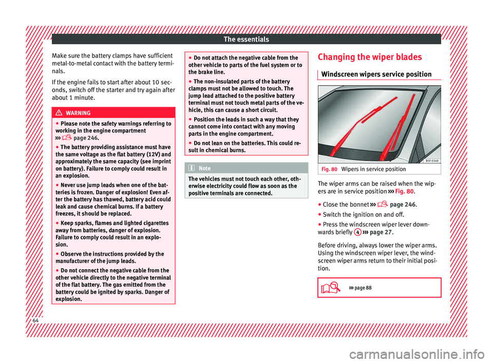
Wipers in service position The wiper arms can be raised when the wip-
er
s
ar
e in service position ››› Fig. 80.
● Close the bonnet ›››
page 246.
● Switch the ignition on and off.
● Press the windscreen wiper lever down-
ward
s briefly 4
› ›
› page 27.
Before driving, always lower the wiper arms.
Using the windscreen wiper lever, the wind-
screen wiper arms return to their initial posi-
tion.
››› page 88 64
Page 69 of 308
Safe driving
● Belt
t
ensioners for the front seats
● Front airbags
● knee airbags,
● Side airbags in the front seat backrests
● Side airbags in the rear seat backrests*
● Head-protection airbags
● “ISOFIX” anchor points for child seats in
the rear s
ide seats with the “ISOFIX” system,
● Height-adjustable front head restraints
● Rear head restraints with in-use position
and non-use pos
ition
● Adjustable steering column
The safety
equipment mentioned above
works together to provide you and your pas-
sengers with the best possible protection in
the event of an accident. However, these
safety systems can only be effective if you
and your passengers are sitting in a correct
position and use this equipment properly.
Safety is everyone's business! Correct position for passengers
Correct
sitting position for driver Fig. 83
The proper distance between driver
and s t
eerin
g wheel Fig. 84
Correct head restraint position for the
driv er
. For your own safety and to reduce the risk of
injur
y
in the ev
ent of an accident, we recom- mend the following adjustments for the driv-
er:
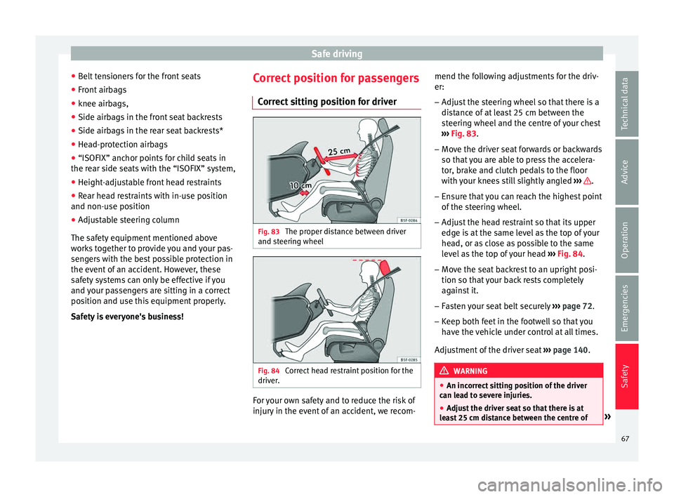
– Adjust the steering wheel so that there is a
dist
ance of at least 25 cm between the
steering wheel and the centre of your chest
››› Fig. 83.
– Move the driver seat forwards or backwards
so that
you are able to press the accelera-
tor, brake and clutch pedals to the floor
with your knees still slightly angled ››› .
– Ensure that you can reach the highest point
of the s
t
eering wheel.
– Adjust the head restraint so that its upper
edge is
at the same level as the top of your
head, or as close as possible to the same
level as the top of your head ››› Fig. 84.
– Move the seat backrest to an upright posi-
tion so that
your back rests completely
against it.
– Fasten your seat belt securely ›››
page 72.
– Keep both feet in the footwell so that you
have the
vehicle under control at all times.
Adjustment of the driver seat ››› page 140. WARNING
● An incorr ect
sitting position of the driver
can lead to severe injuries.
● Adjust the driver seat so that there is at
lea
st 25 cm distance between the centre of » 67
Technical data
Advice
Operation
Emergencies
Safety
Page 73 of 308
Safe driving
Rear head restraints – The rear head restraints have 2 positions:
use
and
non-use.
– One position for use (he
ad restraint raised)
››› Fig. 86. In this position, the head re-
straints are used normally, protecting pas-
sengers along with the rear seat belts.
– And one position for non-use (he
ad re-
straint lowered).
– To fit the head restraints in position for use,
pul
l on the edges with both hands in the
direction of the arrow. WARNING
● Under no cir c
umstances should the rear
passengers travel while the head restraints
are in the non-use position. See the warning
label located on the rear side fixed window
››› Fig. 87.
● Do not swap the centre rear head restraint
with either of the out
er seat rear head re-
straints. Risk of injury in case of an accident! CAUTION
Note the instructions on the adjustment of
the hea d r
estraints ››› page 141. Pedal area
P ed
a
ls –
Ensure that you can always press the accel-
erat or
, brake and clutch pedals unimpaired
to the floor.
– Ensure that the pedals can return unim-
paired t
o their initial positions.
– Ensure that the floor mats are securely fas-
tened during the trip and do not
obstruct
the pedals ››› .
On ly
u
se floor mats which leave the pedals
clear and which are secured to prevent them
from slipping. You can obtain suitable floor
mats from a specialised dealership. Fasten-
ers* for floor mats are fitted in the footwells.
If a brake circuit fails, the brake pedal must
be pressed down thoroughly in order to stop
the vehicle.
Wear suitable footwear
Always wear shoes which support your feet
properly and give you a good feeling for the
pedals. WARNING
● Re s
tricting pedal operation can lead to crit-
ical situations while driving. ●
Never l a
y or fit floor mats or other floor cov-
erings over the original floor mats. This
would reduce the pedal area and could ob-
struct the pedals. Risk of accident.
● Never place objects in the driver footwell.
An obj
ect could move into the pedal area and
impair pedal operation. In the event of a sud-
den driving or braking manoeuvre, you will
not be able to operate the brake, clutch or ac-
celerator pedal. Risk of accident! 71Technical data
Advice
Operation
Emergencies
Safety
Page 89 of 308
Self-help
●
The sea l
ant is a health hazard and must be
cleaned immediately if it comes into contact
with the skin.
● Always keep the tyre mobility set out of the
reac
h of small children.
● Never use an equivalent jack, even if it has
been appro
ved for your vehicle.
● Always stop the engine, apply the hand-
brake l
ever firmly and engage gear if using a
manual gearbox, in order to reduce the risk of
vehicle involuntary movement. WARNING
A tyre filled with sealant does not have the
same per f
ormance properties as a conven-
tional tyre.
● Never drive faster than 80 km/h (50 mph).
● Avoid heavy acceleration, hard braking and
fas
t cornering.
● Drive for only 10 minutes at a maximum
speed of 80
km/h (50 mph) and then check
the tyre. For the sake of the environment
Dispose of used or expired sealant observing
any l
egal requirements. Note
A new bottle of sealant can be purchased at
SEA T de
alerships. Note
Take into account the separate instruction
manua l
of the tyre mobility set* manufactur-
er. Contents of the anti-puncture kit*
Fig. 97
Standard representation: contents of
the anti-p u
nct
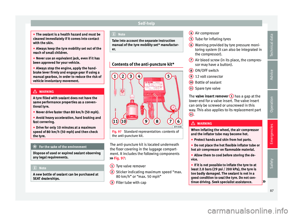
ure kit. The anti-puncture kit is located underneath
the floor c
o
v
ering in the luggage compart-
ment. It includes the following components
››› Fig. 97:
Tyre valve remover
Sticker indicating maximum speed “max.
80 km/h” or “max. 50 mph”
Filler tube with cap
1 2
3 Air compressor
T
ube f
or infl
ating tyres
Warning provided by tyre pressure moni-
toring system (it can also be integrated in
the compressor).
Air bleed screw (in its place, the compres-
sor may have a button).
ON/OFF switch
12 volt connector
Bottle of sealant
Spare tyre valve
The valve insert remover 1 has a gap at the
lo w
er end f
or a valve insert. The valve insert
can only be screwed or unscrewed in this
way. This also applies to its replacement part 11 .
WARNING
When inflating the wheel, the air compressor
and the inflat or t
ube may become hot.
● Protect hands and skin from hot parts.
● Do not place the hot flexible inflator tube or
hot air compr
essor on flammable material.
● Allow them to cool before storing the de-
vice.
● If
it is not possible to inflate the tyre to at
lea
st 2.0 bars (29 psi / 200 kPa), the tyre is
too badly damaged. The sealant is not in a
good condition to seal the tyre. Do not con-
tinue driving. Seek specialist assistance. » 4
5
6
7
8
9
10
11
87
Technical data
Advice
Operation
Emergencies
Safety
Page 94 of 308
Emergencies
●
Never u se a f
use with a higher value. Only
replace fuses with a fuse of the same amper-
age (same colour and markings) and size.
● Never repair a fuse.
● Never replace a fuse by a metal strip, staple
or simil
ar. CAUTION
● To pr ev
ent damage to the vehicle's electric
system, before replacing a fuse always turn
off the ignition, the lights and all electrical
elements and remove the key from the igni-
tion.
● If you replace a fuse with higher-rating
fuse,
you could cause damage to another part
of the electrical system.
● Protect the fuse boxes when open to pre-
vent the entr
y of dust or humidity as they can
damage the electrical system. Note
● One component m
ay have more than one
fuse.
● Several components may run on a single
fuse. Vehicle fuses
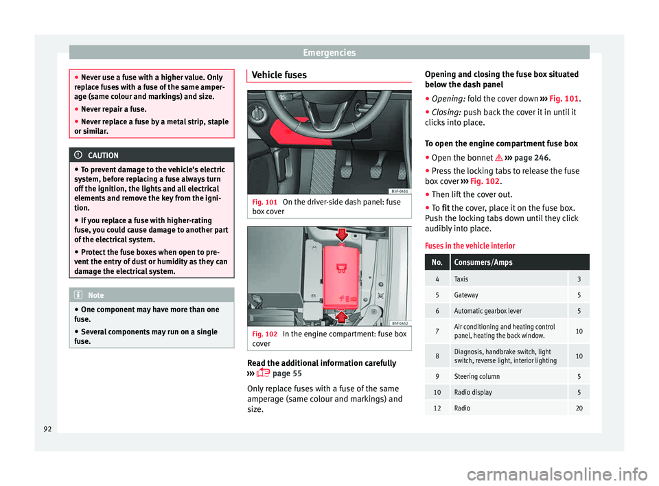
Fig. 101
On the driver-side dash panel: fuse
bo x
c
over Fig. 102
In the engine compartment: fuse box
c o
v
er Read the additional information carefully
› ›
›
page 55
Only replace fuses with a fuse of the same
amperage (same colour and markings) and
size. Opening and closing the fuse box situated
below the da
sh panel
● Opening: fold the cover down ››
› Fig. 101.
● Closing: push back the cover it in until it
clic
ks into place.
To open the engine compartment fuse box
● Open the bonnet ›››
page 246.
● Press the locking tabs to release the fuse
box c
over ››› Fig. 102.
● Then lift the cover out.
● To fit the cover, place it on the fuse box.
Pu
sh the locking tabs down until they click
audibly into place.
Fuses in the vehicle interior
No.Consumers/Amps
4Taxis3
5Gateway5
6Automatic gearbox lever5
7Air conditioning and heating control
panel, heating the back window.10
8Diagnosis, handbrake switch, light
switch, reverse light, interior lighting10
9Steering column5
10Radio display5
12Radio20 92
Page 95 of 308
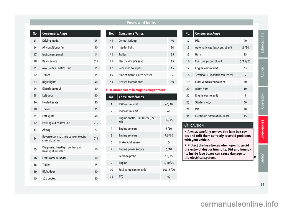
Fuses and bulbsNo.Consumers/Amps
13Driving mode.15
14Air conditioner fan30
17Instrument panel5
18Rear camera7.5
214x4 Haldex Control Unit15
22Trailer15
23Right lights40
24Electric sunroof30
25Left door30
26Heated seats20
28Trailer25
31Left lights40
32Parking aid control unit7.5
33Airbag5
34Reverse switch, clima sensor, electro-
chromic mirror7.5
35Diagnosis, headlight control unit,
headlight adjuster10
36Front camera, Radar10
38Trailer25
39Right door30
4012V socket20
No.Consumers/Amps
42Central locking40
43Interior light30
44Trailer15
45Electric driver's seat15
47Rear window wiper15
49Starter motor; clutch sensor5
53Heated rear window30
Fuse arrangement in engine compartment
No.Consumers/Amps
1ESP control unit40/20
2ESP control unit40
3Engine control unit (diesel/pet-
rol)30/15
4Engine sensors5/10
5Engine sensors7.5/10
6Brake light sensor5
7Engine power supply5/10
8Lambda probe10/15
9Engine5/10/20
10Fuel pump control unit10/15/20
11PTC40
No.Consumers/Amps
12PTC40
13Automatic gearbox control unit15/30
15Horn15
16Fuel pump control unit5/15/20
17Engine control unit7.5
18Terminal 30 (positive reference)5
19Front windscreen washer30
20Alarm horn10
22Engine control unit5
23Starter motor30
24PTC40
31Electronic differential CUPRA15
CAUTION
● Alw a
ys carefully remove the fuse box cov-
ers and refit them correctly to avoid problems
with your vehicle.
● Protect the fuse boxes when open to avoid
the entry of
dust or humidity. Dirt and humid-
ity inside fuse boxes can cause damage to
the electrical system. » 93
Technical data
Advice
Operation
Emergencies
Safety
Page 99 of 308
Fuses and bulbs
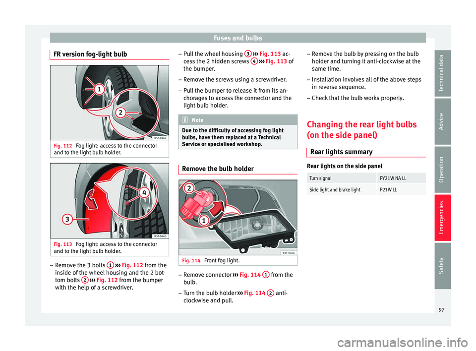
FR version fog-light bulb Fig. 112
Fog light: access to the connector
and t o the light
b
ulb holder. Fig. 113
Fog light: access to the connector
and t o the light
b
ulb holder. –
Remove the 3 bolts 1
› ›
› Fig. 112
from the
inside of the wheel housing and the 2 bot-
tom bolts 2
› ›
› Fig. 112
from the bumper
with the help of a screwdriver. –
Pul
l the wheel housing 3
› ››
Fig. 113
ac -
cess the 2 hidden screws 4
› ››
Fig. 113
of
the b
umper.
– Remove the screws using a screwdriver.
– Pull the bumper to release it from its an-
chorag
es to access the connector and the
light bulb holder. Note
Due to the difficulty of accessing fog light
bu l
bs, have them replaced at a Technical
Service or specialised workshop. Remove the bulb holder
Fig. 114
Front fog light. –
Remove connector ››
›
Fig. 114 1 from the
b ul
b.
– Turn the bulb holder ›››
Fig. 114 2 anti-
c loc
k
wise and pull. –
Remov
e the bulb by pressing on the bulb
holder and turning it anti-clockwise at the
same time.
– Installation involves all of the above steps
in rever
se sequence.
– Check that the bulb works properly.
Changing the rear light bulbs
(on the side panel) R
ear lights summary Rear lights on the side panel
Turn signalPY21W NA LL
Side light and brake lightP21W LL
97
Technical data
Advice
Operation
Emergencies
Safety
Page 105 of 308
Controls and displays
Operation
C ontr
o
ls and displays
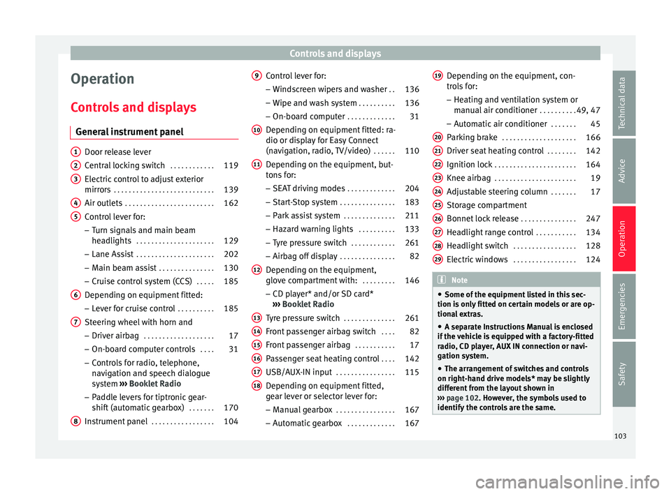
General instrument panel Door release lever
Centr
al
locking switch . . . . . . . . . . . .119
Electric control to adjust exterior
mirrors . . . . . . . . . . . . . . . . . . . . . . . . . . . 139
Air outl
ets . . . . . . . . . . . . . . . . . . . . . . . . 162
Control lever for:
– Turn s ign
als and main beam
headlights . . . . . . . . . . . . . . . . . . . . . 129
– Lane Ass i
st . . . . . . . . . . . . . . . . . . . . . 202
– Main beam a
ssist . . . . . . . . . . . . . . . 130
– Cruise c
ontrol system (CCS) . . . . .185
Depending on equipment fitted:
– Lev er f
or cruise control . . . . . . . . . .185
Steering wheel with horn and – Driver airbag . . . . . . . . . . . . . . . . . . . 17
– On-boar d c
omputer controls . . . .31
– Contro
ls for radio, telephone,
navigation and speech dialogue
system ›››
Booklet Radio
– Paddle levers for tiptronic gear-
shift (automatic gearbox) . . . . . . .170
Instrument panel . . . . . . . . . . . . . . . . . 104
1 2
3
4
5
6
7
8 Control lever for:
– Wind
s
creen wipers and washer . .136
– Wipe and wa
sh system . . . . . . . . . . 136
– On-board c
omputer . . . . . . . . . . . . . 31
Depending on equipment fitted: ra-
dio or disp
lay for Easy Connect
(navigation, radio, TV/video) . . . . . .110
Depending on the equipment, but-
tons
for:
– SEAT driving modes . . . . . . . . . . . . .204
– Star t
-Stop system . . . . . . . . . . . . . . . 183
– Park a
ssist system . . . . . . . . . . . . . . 211
– Hazard w
arning lights . . . . . . . . . .133
– Tyr
e pressure switch . . . . . . . . . . . .261
– Airbag off di
splay . . . . . . . . . . . . . . . 82
Depending on the equipment,
glov e c
ompartment with: . . . . . . . . .146
– CD pl a
yer* and/or SD card*
››› Booklet Radio
Tyre pressure switch . . . . . . . . . . . . . .261
Front passenger airbag switch . . . .82
Front passenger airbag . . . . . . . . . . .17
Passenger seat heating control . . . .142
USB/AUX-IN input . . . . . . . . . . . . . . . . 115
Depending on equipment fitted,
ge ar l
ever or selector lever for:
– Manual gearbox . . . . . . . . . . . . . . . . 167
– Autom atic
gearbox . . . . . . . . . . . . . 167
9
10
11
12
13
14
15
16
17
18 Depending on the equipment, con-
tr
o
l
s for:
– Heating and ventilation system or
manual air conditioner . . . . . . . . . .49, 47
– Automatic
air conditioner . . . . . . .45
Parking brake . . . . . . . . . . . . . . . . . . . . 166
Driver seat heating control . . . . . . . .142
Ignition lock . . . . . . . . . . . . . . . . . . . . . . 164
Knee airbag . . . . . . . . . . . . . . . . . . . . . . 19
Adjustable steering column . . . . . . .17
Storage compartment
Bonnet lock
release . . . . . . . . . . . . . . . 247
Headlight range control . . . . . . . . . . .134
Headlight switch . . . . . . . . . . . . . . . . . 128
Electric windows . . . . . . . . . . . . . . . . . 124 Note
● Some of the equipment li
sted in this sec-
tion is only fitted on certain models or are op-
tional extras.
● A separate Instructions Manual is enclosed
if the v
ehicle is equipped with a factory-fitted
radio, CD player, AUX IN connection or navi-
gation system.
● The arrangement of switches and controls
on right-hand driv
e models* may be slightly
different from the layout shown in
››› page 102. However, the symbols used to
identify the controls are the same. 19
20
21
22
23
24
25
26
27
28
29
103
Technical data
Advice
Operation
Emergencies
Safety
Page 135 of 308
Lights and visibility
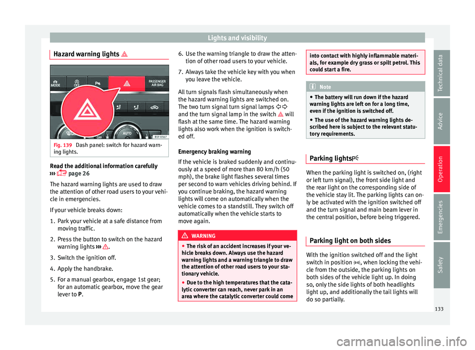
Hazard warning lights Fig. 139
Dash panel: switch for hazard warn-
in g lights. Read the additional information carefully
› ›
›
page 26
The hazard warning lights are used to draw
the attention of other road users to your vehi-
cle in emergencies.
If your vehicle breaks down:
1. Park your vehicle at a safe distance from movin
g traffic.
2. Press the button to switch on the hazard warning lights
››› .
3. Switch the ignition off.
4. Apply the handbrake.
5. For a manual gearbox, engage 1st gear; for an aut
om
atic gearbox, move the gear
lever to P. 6. Use the warning triangle to draw the atten-
tion of other ro
ad users to your vehicle.
7. Always take the vehicle key with you when you le
ave the vehicle.
All turn signals flash simultaneously when
the hazard warning lights are switched on.
The two turn signal turn signal lamps
and the turn signal lamp in the switch will
flash at the same time. The hazard warning
lights also work when the ignition is switch-
ed off.
Emergency braking warning
If the vehicle is braked suddenly and continu-
ously at a speed of more than 80 km/h (50
mph), the brake light flashes several times
per second to warn vehicles driving behind. If
you continue braking, the hazard warning
lights will come on automatically when the
vehicle comes to a standstill. They switch off
automatically when the vehicle starts to
move again. WARNING
● The risk of
an accident increases if your ve-
hicle breaks down. Always use the hazard
warning lights and a warning triangle to draw
the attention of other road users to your sta-
tionary vehicle.
● Due to the high temperatures that the cata-
lytic con
verter can reach, never park in an
area where the catalytic converter could come into contact with highly inflammable materi-
al
s, f
or example dry grass or spilt petrol. This
could start a fire. Note
● The b atter
y will run down if the hazard
warning lights are left on for a long time,
even if the ignition is switched off.
● The use of the hazard warning lights de-
scribed her
e is subject to the relevant statu-
tory requirements. Parking lights
When the parking light is switched on, (right
or l
ef
t
turn signal), the front side light and
the rear light on the corresponding side of
the vehicle stay lit. The parking lights can on-
ly be activated with the ignition switched off
and the turn signal and main beam lever in
the central position, before being triggered.
Parking light on both sides With the ignition switched off and the light
sw
it
c
h in position , when locking the vehi-
cle from the outside, the parking lights on
both sides of the vehicle light up. In doing
so, only the side lights of both headlights
light up, and additionally the tail lights will
do so partially.
133
Technical data
Advice
Operation
Emergencies
Safety
Page 151 of 308
Transport and practical equipment
– Att ac
h the s
traps to the rear lid A
› ›› .
WARNING
● The lugg ag
e compartment cover must al-
ways be fixed properly (risk of accident).
● The luggage compartment cover should not
be used as
a storage shelf. Articles placed on
this cover could cause injury to vehicle occu-
pants in an accident or if the brakes are ap-
plied suddenly. Retractable rear shelf
3 App
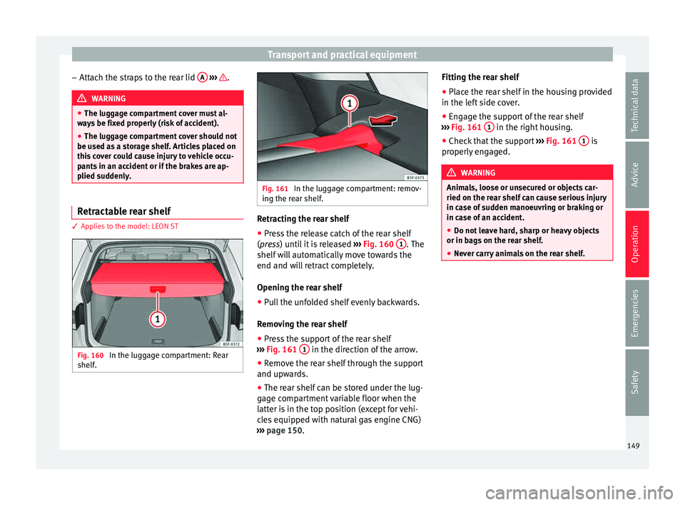
lies to the model: LEON ST Fig. 160
In the luggage compartment: Rear
shelf . Fig. 161
In the luggage compartment: remov-
ing the r e
ar shelf. Retracting the rear shelf
● Press the release catch of the rear shelf
(pr e
s
s) until it is released ››› Fig. 160 1 . The
shelf w
i
ll automatically move towards the
end and will retract completely.
Opening the rear shelf
● Pull the unfolded shelf evenly backwards.
Remov
ing the rear shelf
● Press the support of the rear shelf
›››
Fig. 161 1 in the direction of the arrow.
● Remove the rear shelf through the support
and up w
ar
ds.
● The rear shelf can be stored under the lug-
gage c
ompartment variable floor when the
latter is in the top position (except for vehi-
cles equipped with natural gas engine CNG)
››› page 150. Fitting the rear shelf
● Place the rear shelf in the housing provided
in the left
side cover.
● Engage the support of the rear shelf
›››
Fig. 161 1 in the right housing.
● Check that the support ››
›
Fig. 161 1 is
pr operly
en
gaged. WARNING
Animals, loose or unsecured or objects car-
ried on the re ar shelf
can cause serious injury
in case of sudden manoeuvring or braking or
in case of an accident.
● Do not leave hard, sharp or heavy objects
or in bags
on the rear shelf.
● Never carry animals on the rear shelf. 149
Technical data
Advice
Operation
Emergencies
Safety