parking brake Seat Leon Sportstourer 2016 Owner's manual
[x] Cancel search | Manufacturer: SEAT, Model Year: 2016, Model line: Leon Sportstourer, Model: Seat Leon Sportstourer 2016Pages: 324, PDF Size: 6.93 MB
Page 8 of 324
Table of Contents
Front Assist system including City emergency
br ak
in
g and pedestrian monitoring* . . . . . . . . 207
Lane Assist system* . . . . . . . . . . . . . . . . . . . . . . 213
Traffic Jam Assist . . . . . . . . . . . . . . . . . . . . . . . . 216
Emergency Assist . . . . . . . . . . . . . . . . . . . . . . . . 217
SEAT Drive Profile* . . . . . . . . . . . . . . . . . . . . . . . 219
Traffic sign detection system . . . . . . . . . . . . . . . 222
Fatigue detection (break recommendation)* . . 224
Parking aid . . . . . . . . . . . . . . . . . . . . . . . . . . . . . 225
Rear Assist “Rear View Camera”* . . . . . . . . . . . 231
Towing bracket device . . . . . . . . . . . . . . . . . . . . 234
Towing bracket device* . . . . . . . . . . . . . . . . . . . 234
Trailer towing . . . . . . . . . . . . . . . . . . . . . . . . . . . 239
Advice . . . . . . . . . . . . . . . . . . . . . . . . . . . . . . . . 245
Care and maintenance . . . . . . . . . . . . . . . . . . . . 245
Accessories and modifications to the vehi-
cle
. . . . . . . . . . . . . . . . . . . . . . . . . . . . . . . . . . . . 245
Care and cleaning . . . . . . . . . . . . . . . . . . . . . . . 246
Vehicle exterior care . . . . . . . . . . . . . . . . . . . . . . 246
Caring for the vehicle interior . . . . . . . . . . . . . . 250
Intelligent technology . . . . . . . . . . . . . . . . . . . . 253
Electromechanical steering . . . . . . . . . . . . . . . . 253
Progressive steering . . . . . . . . . . . . . . . . . . . . . 254
Four-wheel drive . . . . . . . . . . . . . . . . . . . . . . . . . 254
Power Management . . . . . . . . . . . . . . . . . . . . . . 255
Checking and refilling levels . . . . . . . . . . . . . . . 256
Filling the tank . . . . . . . . . . . . . . . . . . . . . . . . . . 256
Fuel . . . . . . . . . . . . . . . . . . . . . . . . . . . . . . . . . . . 258
Engine compartment . . . . . . . . . . . . . . . . . . . . . 262
Engine oil . . . . . . . . . . . . . . . . . . . . . . . . . . . . . . 264
Cooling system . . . . . . . . . . . . . . . . . . . . . . . . . . 266
Brake fluid . . . . . . . . . . . . . . . . . . . . . . . . . . . . . 267
Windscreen washer reservoir . . . . . . . . . . . . . . 268
Battery . . . . . . . . . . . . . . . . . . . . . . . . . . . . . . . . . 269
Wheels . . . . . . . . . . . . . . . . . . . . . . . . . . . . . . . . 271
Wheels and tyres . . . . . . . . . . . . . . . . . . . . . . . . 271
Tyre monitoring systems . . . . . . . . . . . . . . . . . . 275 Temporary spare wheel . . . . . . . . . . . . . . . . . . . 278
Winter service . . . . . . . . . . . . . . . . . . . . . . . . . . . 279
Technical data . . . . . . . . . . . . . . . . . . . . . . . . 281
Technical specifications . . . . . . . . . . . . . . . . . . 281
Important . . . . . . . . . . . . . . . . . . . . . . . . . . . . . . 281
Vehicle identification data . . . . . . . . . . . . . . . . . 281
Information on fuel consumption . . . . . . . . . . . 282
Trailer mode . . . . . . . . . . . . . . . . . . . . . . . . . . . . 282
Wheels . . . . . . . . . . . . . . . . . . . . . . . . . . . . . . . . 283
Engine data . . . . . . . . . . . . . . . . . . . . . . . . . . . . . 284
Dimensions . . . . . . . . . . . . . . . . . . . . . . . . . . . . . 305
Index . . . . . . . . . . . . . . . . . . . . . . . . . . . . . . . . . 307
6
Page 42 of 324
The essentials
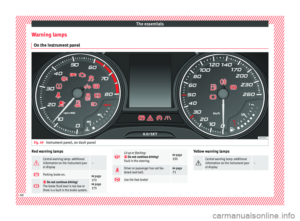
Warning lamps On the in s
trument
panelFig. 49
Instrument panel, on dash panel Red warning lamps
Central warning lamp: additional
information on the instrument pan-
el display–
Parking brake on.›››
page
172
››› page
175
Do not continue driving!
The brake fluid level is too low or
there is a fault in the brake system.
Lit up or flashing: Do not continue driving!
Fault in the steering.››› page
253
Driver or passenger has not fas-
tened seat belt.›››
page
71
Use the foot brake! Yellow warning lamps
Central warning lamp: additional
information on the instrument pan-
el display–
40
Page 45 of 324
The essentials
● Pr e
s
s the clutch pedal and keep your foot
right down.
● Move the gearbox lever to the required po-
sition.
● Rel
ease the clutch.
Selecting r
everse gear
● Press the clutch pedal and keep your foot
right down.
● W
ith the gearbox lever in neutral, push it
upwar
ds, move it to the left as far as it will go
and then forwards to select reverse ››› Fig. 52
R .
● Release the clutch.
››› in Changing gear on page 179
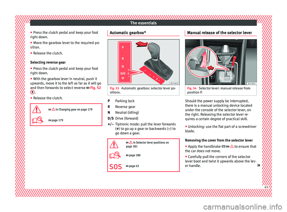
››› page 179 Automatic gearbox*
Fig. 53
Automatic gearbox: selector lever po-
s ition
s. Parking lock
R
ev
er
se gear
Neutral (idling)
Drive (forward)
Tiptronic mode: pull the lever forwards
(+) to go up a gear or backwards ( –) to
go down a gear.
››› in Selector lever positions on
page 181
››› page 180
››› page 43 P
R
N
D/S
+/–
Manual release of the selector lever Fig. 54
Selector lever: manual release from
po s
ition P
. Should the power supply be interrupted,
ther
e i
s
a manual unlocking device located
under the console of the selector lever, on
the right. Releasing the selector lever re-
quires a certain degree of practical skill.
● Unlocking: use the flat part of a screwdriver
bla
de.
Removing the cover from the selector lever
● Apply the handbrake ›››
to ensure that
the c ar doe
s
not move.
● Carefully pull the corners of the selector
lever boot
and twist it upwards above the lev-
er handle. » 43
Page 91 of 324
Self-help
●
Swit c
h on the hazard warning lights of both
vehicles. However, observe any regulations
to the contrary.
● The tow rope must not be twisted. Other-
wise the fr
ont tow line anchorage could be
pulled off the vehicle. Indications for tow-starting
Vehicle's should not generally be tow-star-
ted.
The jump s
tart should be used instead
››› page 61.
For technical reasons, towing the following
vehicles is not allowed:
● Vehicles with an automatic gearbox.
● If the vehicle battery is discharged, be-
cau se in
vehicles with the Keyless Access
locking and ignition system the steering re-
mains locked and the electronic parking
brake cannot be deactivated nor can the elec-
tronic lock of the steering column be re-
leased if they are activated.
● If the battery is flat, it is possible that the
engine contr
ol units may not operate correct-
ly.
However, if the vehicle must absolutely be
tow-started (in the case of manual gearbox-
es):
● Engage the 2nd or 3rd gear. ●
Keep the clut
ch pressed down.
● Switch on the ignition and the hazard warn-
ing lights.
● Once both
vehicles are moving, release the
clutc
h.
● Once the engine starts, press the clutch
and diseng
age the gear to avoid colliding
with the towing vehicle. Note
The vehicle can only be tow-started if the
electr onic
parking brake and, if appropriate,
the electronic lock of the steering column are
deactivated. If the vehicle has no power sup-
ply or there is an electric system fault, the
engine must be tow-started to deactivate the
electronic parking brake and the electronic
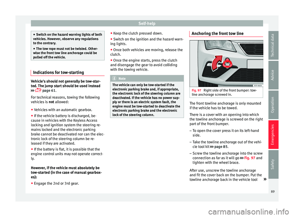
lock of the steering column. Anchoring the front tow line
Fig. 97
Right side of the front bumper: tow-
line anc hor
ag
e screwed in. The front towline anchorage is only mounted
if
the
v
ehicle has to be towed.
There is a cover with an opening into which
the towline anchorage is screwed on the right part of the front bumper.
– To open the cover press it on its left-hand
side.
– Tak
e the towline anchorage out of the vehi-
cle t
ool kit ››› page 85.
– Screw the towline anchorage into the screw
connection as
far as it will go ›››
Fig. 97 and
tighten with the wheel brace.
After use, unscrew the towline anchorage
and fit the cover back on the bumper. Put the
towline anchorage back in the vehicle tool »
89
Technical data
Advice
Operation
Emergencies
Safety
Page 94 of 324
Emergencies
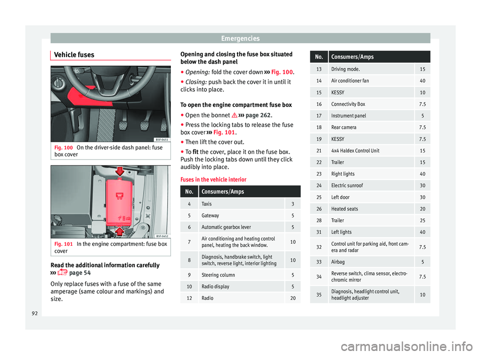
Vehicle fuses Fig. 100
On the driver-side dash panel: fuse
bo x
c
over Fig. 101
In the engine compartment: fuse box
c o
v
er Read the additional information carefully
› ›
›
page 54
Only replace fuses with a fuse of the same
amperage (same colour and markings) and
size. Opening and closing the fuse box situated
below the da
sh panel
● Opening: fold the cover down ››
› Fig. 100.
● Closing: push back the cover it in until it
clic
ks into place.
To open the engine compartment fuse box
● Open the bonnet ›››
page 262.
● Press the locking tabs to release the fuse
box c
over ››› Fig. 101.
● Then lift the cover out.
● To fit the cover, place it on the fuse box.
Pu
sh the locking tabs down until they click
audibly into place.
Fuses in the vehicle interior
No.Consumers/Amps
4Taxis3
5Gateway5
6Automatic gearbox lever5
7Air conditioning and heating control
panel, heating the back window.10
8Diagnosis, handbrake switch, light
switch, reverse light, interior lighting10
9Steering column5
10Radio display5
12Radio20
No.Consumers/Amps
13Driving mode.15
14Air conditioner fan40
15KESSY10
16Connectivity Box7.5
17Instrument panel5
18Rear camera7.5
19KESSY7.5
214x4 Haldex Control Unit15
22Trailer15
23Right lights40
24Electric sunroof30
25Left door30
26Heated seats20
28Trailer25
31Left lights40
32Control unit for parking aid, front cam-
era and radar7.5
33Airbag5
34Reverse switch, clima sensor, electro-
chromic mirror7.5
35Diagnosis, headlight control unit,
headlight adjuster10 92
Page 105 of 324
Controls and displays
Operation
C ontr
o
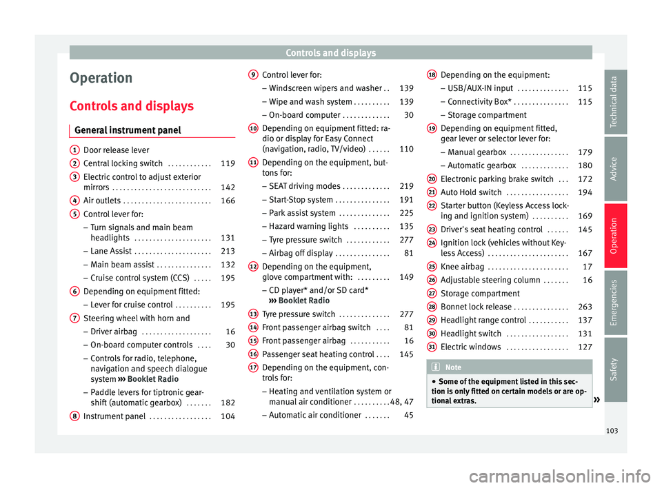
ls and displays
General instrument panel Door release lever
Centr
al
locking switch . . . . . . . . . . . .119
Electric control to adjust exterior
mirrors . . . . . . . . . . . . . . . . . . . . . . . . . . . 142
Air outl
ets . . . . . . . . . . . . . . . . . . . . . . . . 166
Control lever for:
– Turn s ign
als and main beam
headlights . . . . . . . . . . . . . . . . . . . . . 131
– Lane Ass i
st . . . . . . . . . . . . . . . . . . . . . 213
– Main beam a
ssist . . . . . . . . . . . . . . . 132
– Cruise c
ontrol system (CCS) . . . . .195
Depending on equipment fitted:
– Lev er f
or cruise control . . . . . . . . . .195
Steering wheel with horn and – Driver airbag . . . . . . . . . . . . . . . . . . . 16
– On-boar d c
omputer controls . . . .30
– Contro
ls for radio, telephone,
navigation and speech dialogue
system ›››
Booklet Radio
– Paddle levers for tiptronic gear-
shift (automatic gearbox) . . . . . . .182
Instrument panel . . . . . . . . . . . . . . . . . 104
1 2
3
4
5
6
7
8 Control lever for:
– Wind
s
creen wipers and washer . .139
– Wipe and wa
sh system . . . . . . . . . . 139
– On-board c
omputer . . . . . . . . . . . . . 30
Depending on equipment fitted: ra-
dio or disp
lay for Easy Connect
(navigation, radio, TV/video) . . . . . .110
Depending on the equipment, but-
tons
for:
– SEAT driving modes . . . . . . . . . . . . .219
– Star t
-Stop system . . . . . . . . . . . . . . . 191
– Park a
ssist system . . . . . . . . . . . . . . 225
– Hazard w
arning lights . . . . . . . . . .135
– Tyr
e pressure switch . . . . . . . . . . . .277
– Airbag off di
splay . . . . . . . . . . . . . . . 81
Depending on the equipment,
glov e c
ompartment with: . . . . . . . . .149
– CD pl a
yer* and/or SD card*
››› Booklet Radio
Tyre pressure switch . . . . . . . . . . . . . .277
Front passenger airbag switch . . . .81
Front passenger airbag . . . . . . . . . . .16
Passenger seat heating control . . . .145
Depending on the equipment, con-
tro l
s for:
– Heating and ventilation system or
manual air conditioner . . . . . . . . . .48, 47
– Autom atic
air conditioner . . . . . . .45
9
10
11
12
13
14
15
16
17 Depending on the equipment:
– USB/A UX
-IN inp
ut . . . . . . . . . . . . . . 115
– Connectivity
Box* . . . . . . . . . . . . . . . 115
– Storag
e compartment
Depending on equipment fitted,
gear lever or selector lever for: – Manual gearbox . . . . . . . . . . . . . . . . 179
– Automatic
gearbox . . . . . . . . . . . . . 180
Electronic parking brake switch . . .172
Auto Hold switch . . . . . . . . . . . . . . . . . 194
Starter button (Keyless Access lock-
ing and ignition sys
tem) . . . . . . . . . . 169
Driver's seat heating control . . . . . .145
Ignition lock (vehicles without Key-
les
s Access) . . . . . . . . . . . . . . . . . . . . . . 167
Knee airbag . . . . . . . . . . . . . . . . . . . . . . 17
Adjustable steering column . . . . . . .16
Storage compartment
Bonnet lock
release . . . . . . . . . . . . . . . 263
Headlight range control . . . . . . . . . . .137
Headlight switch . . . . . . . . . . . . . . . . . 131
Electric windows . . . . . . . . . . . . . . . . . 127 Note
● Some of the equipment li
sted in this sec-
tion is only fitted on certain models or are op-
tional extras. » 18
19
20
21
22
23
24
25
26
27
28
29
30
31
103
Technical data
Advice
Operation
Emergencies
Safety
Page 138 of 324
Operation
6. Use the warning triangle to draw the atten- tion of other r
o
ad users to your vehicle.
7. Always take the vehicle key with you when you le
ave the vehicle.
All turn signals flash simultaneously when
the hazard warning lights are switched on.
The two turn signal turn signal lamps
and the turn signal lamp in the switch will
flash at the same time. The simultaneous
hazard warning lights also work when the ig-
nition is switched off.
Emergency braking warning
If the vehicle brakes suddenly and continu-
ously at a speed of more than 80 km/h (50
mph), the brake light flashes several times
per second to warn the vehicles driving be-
hind. If you continue braking, the hazard
warning lights will come on automatically
when the vehicle comes to a standstill. They
switch off automatically when the vehicle
starts to move again. WARNING
● The risk of
an accident increases if your ve-
hicle breaks down. Always use the hazard
warning lights and a warning triangle to draw
the attention of other road users to your sta-
tionary vehicle.
● Due to the high temperatures that the cata-
lytic con
verter can reach, never park in an
area where the catalytic converter could come into contact with highly inflammable materi-
al
s, f
or example dry grass or spilt petrol. This
could start a fire. Note
● The b atter
y will run down if the hazard
warning lights are left on for a long time,
even if the ignition is switched off.
● The use of the hazard warning lights de-
scribed her
e is subject to the relevant statu-
tory requirements. Parking lights
When the parking light is switched on, (right
or l
ef
t
turn signal), the front side light and
the rear light on the corresponding side of
the vehicle stay lit. The parking lights can on-
ly be activated with the ignition switched off
and the turn signal and main beam lever in
the central position, before being triggered.
Parking light on both sides With the ignition switched off and the light
sw
it
c
h in position , when locking the vehi-
cle from the outside, the parking lights on
both sides of the vehicle light up. In doing
so, only the side lights of both headlights
light up, and additionally the tail lights will
do so partially. Motorway light* The motorway light is available on vehicles
equipped w
ith f
ull-LED lights.
The function is connected/disconnected via
the corresponding Easy Connect system
menu.
● Activation: when going abo
ve 110 km/h
(68 mph) for more than 30 seconds, the dip-
ped beam raises slightly to increase the driv-
er's visibility distance.
● Deactivation: when reduc in
g the speed of
the car below 100 km/h (62 mph), the dip-
ped beam returns to its normal position.
Driving abroad The light beam of the dipped beam lights is
a
symmetric: the s
ide of
the road on which
you are driving is lit more intensely.
When a car that is manufactured in a country
that drives on the right travels to a country
that drives on the left (or vice versa), it is nor-
mally necessary to cover part of the headlight
bulbs with stickers or to change the adjust-
ment of the headlights to avoid dazzling oth-
er drivers.
In such cases, the regulations specify certain
light values that must be complied with for
designated points of the light distribution.
This is known as “Tourist light”.
136
Page 171 of 324
Driving
●
Vehic l
es with automatic gearbox: after
switching off the ignition, you can only re-
move the ignition key if the selector lever is
in position “P” (parking lock). Next, the se-
lector lever is locked. Switching off the engine with the key
Switching off the engine
– Stop the vehicle.
– Turn the ignition key to position 1›››
Fig. 186.
Eng agin
g the steering wheel lock
In vehicles with automatic gearbox, the igni-
tion key can only be removed when the selec-
tor lever is in position P.
– Remove the key from the ignition in posi-
tion 1
› ›
› Fig. 186
››› .
– Turn the steering wheel until you hear it en-
gag
e.
P
ossible vehicle theft is prevented with the
steering lock engaged. WARNING
● Never sw it
ch the engine off until the vehi-
cle is stationary. The brake servo and power
steering functions will not be completely cov-
ered under warranty. More force may also be
needed to turn the steering wheel or to brake. As you cannot steer and brake in the normal
manner
, ther
e is a greater risk of accidents
and serious injury.
● Never remove the key from the ignition if
the vehic
le is in motion. Otherwise, the steer-
ing could suddenly lock, making it impossible
to steer the vehicle: risk of accident!
● Always take the key with you when you
leav
e the vehicle. This is particularly impor-
tant if there are children in the vehicle, as
they might otherwise be able to start the en-
gine or use power-operated equipment (e.g.
the electric windows), which could cause in-
juries. CAUTION
If the engine has been running under high
loa d f
or a long time, there is a risk of heat
building up in the engine compartment after
it has been switched off; this could cause en-
gine damage. For this reason, you should idle
the engine for approximately 2 minutes be-
fore you switch it off. Note
● Aft er the en
gine is switched off the radiator
fan may run on for up to 10 minutes, even if
the ignition is switched off. It is also possible
that the fan turns itself on once more if the
coolant temperature increases due to the
heat accumulated in the engine compartment
or due to its prolonged exposure to solar ra-
diation. ●
If the v
ehicle is stopped and the Start-Stop
system* switches off the engine, the ignition
remains switched on. Make sure that the igni-
tion is switched off before leaving the vehi-
cle, otherwise the battery could discharge. Starter button*
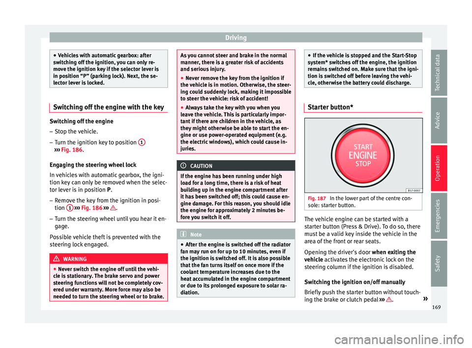
Fig. 187
In the lower part of the centre con-
so l
e: s
tarter button. The vehicle engine can be started with a
s
t
ar
ter button (Press & Drive). To do so, there
must be a valid key inside the vehicle in the
area of the front or rear seats.
Opening the driver's door when exiting the
vehicle activates the electronic lock on the
steering column if the ignition is disabled.
Switching the ignition on/off manually
Briefly push the starter button without touch-
ing the brake or clutch pedal ››› .
»
169
Technical data
Advice
Operation
Emergencies
Safety
Page 172 of 324
Operation
For vehicles with both manual and automatic
tr an
smi
ssion, the starter button text
START ENGINE STOP flashes like a heartbeat
when the sy s
t
em is preset for switching the
ignition on and off.
Automatic ignition switch-off
If the driver leaves the vehicle, taking the ve-
hicle key with them but leaving the ignition
on, the ignition is switched off automatically
after a certain time. If at that time the dipped
beam is on, the parking lights will stay on for
approx. 30 minutes. The side light can be
turned off by blocking the vehicle
››› page 116 or manually ››› page 131.
Emergency starting function
If no valid key is detected inside the vehicle,
an emergency start-up will be required. The
relevant message will appear in the dash
panel display. This may happen when, for ex-
ample, the battery of the vehicle key button
is very low or flat: ● Immediately after pushing the starter but-
ton, keep the
vehicle key next to the right
trim of the steering column.
● The ignition connects and the engine starts
automatic
ally. Emergency disconnection
If the engine doe
s not switch off after briefly
pressing the starter button, an emergency
disconnect will be required:
● Press the starter button twice within 3 sec-
onds or pr
ess it once for more than 1 sec-
ond ››› .
● The engine turns off automatically.
En gine r
e
start feature
If no valid key is detected inside the vehicle
after the engine stops, you will only have 5
seconds to restart it. A warning will display
on the dash panel screen.
After this interval, it will not be possible to
start the engine without a valid key inside
the vehicle.
Automatic deactivation of the ignition on ve-
hicles with the Start-Stop system
The ignition is switched off automatically
when the vehicle is stopped and the auto-
matic engine shutdown is active, if:
● The driver's seat belt is not fastened,
● the driver does not step on any pedal,
● the driver door is opened.
After aut
omatically turning off the ignition, if
the dipped beam is on, the side light re-
mains on for approx. 30 minutes (if the bat-
tery is sufficiently charged). If the driver locks the vehicle or manually turns off the light, the
side light g
oes out. WARNING
Any accidental movement of the vehicle could
re s
ult in serious injury.
● When switching on the ignition, do not
pre
ss the brake or clutch pedal, otherwise
the engine could start immediately. WARNING
If vehicle keys are used negligently or with-
out due c ar
e, this may cause accidents and
serious injury.
● Never leave any key inside the vehicle
when exitin
g. Otherwise, a child or unauthor-
ised person could lock the vehicle, start the
engine or connect the ignition and, in this
way, operate electronic equipment (e.g. the
windows). Note
● Bef or
e leaving the vehicle, always discon-
nect the ignition manually and, if appropri-
ate, take into account the instructions on the
screen of the dash panel.
● If the vehicle is stationary for a long time
with the ignition on, the v
ehicle battery
might be discharged and it might not be pos-
sible to start the engine.
● In diesel vehicles, there may be a delay in
the engine st
arting if it requires preheating.170
Page 173 of 324
Driving
●
If durin g the
STOP phase you press the
START ENGINE STOP button, the ignition is
swit c
hed off and the button flashes.
● If the indication “Start-Stop system deacti-
vated:
Start the engine manually” is dis-
played on the dash panel display, the START ENGINE STOP button will blink.
Starting the engine
3 Valid for vehicles: with starter button.
StepStarting the engine with the starter but-
ton
››› page 169.
1.Press and hold the brake pedal until step 5 is
performed.
1a.In vehicles with a manual gearbox: press and
hold the clutch down until the engine starts.
2.Put the gearbox lever in neutral or the selector
lever in position P or N.
3.
Briefly press the starter button ››› Fig. 187 with-
out pressing the accelerator. For the engine to
start there must be a valid key in the vehicle.
After starting the engine, the light of the START ENGINE STOP
button changes to a fixed
light indicating that the engine has started.
4.If the engine does not start, stop and wait for
approx. 1 minute before trying again. If neces-
sary, perform an emergency start ››› page 170.
5.Disconnect the electronic parking brake when
you are about to start driving ››› page 172. WARNING
Never leave the vehicle with the engine run-
ning, e s
pecially if a gear or gear range is en-
gaged. The vehicle could then suddenly move
or something strange could happen that
would cause damage, fire or serious injury. WARNING
Cold start sprays could explode or cause a
sud den inc
rease in the engine speed.
● Never use sprays to cold start the engine. CAUTION
● The st ar
ter motor or the engine may be
damaged if you try to start the engine while
driving or if you restart it immediately after
switching it off.
● If the engine is cold, avoid high engine
speeds, p
ushing the engine too hard and rap-
id acceleration.
● Do not start the engine by pushing the ve-
hicle or t
owing it. Unburnt fuel could enter
the catalytic converter and damage it. Note
● Do not w ait
until the engine warms up with
the vehicle stationary; if you have good visi-
bility through the windows, start driving im-
mediately. This helps the engine reach oper-
ating temperature faster and reduces emis-
sions. ●
Electric a
l components with a high power
consumption are switched off temporarily
when the engine starts.
● When starting with a cold engine, noise
level
s may briefly increase. This is quite nor-
mal, and no cause for concern.
● When the outside temperature is below
+5°C (+41°F), if the en
gine is diesel, some
smoke may appear under the vehicle when the fuel-operated auxiliary heater is on. Stopping the engine
3 V
alid for vehicles: with starter button.
StepSwitch off the engine with the starter
button ››› page 169.
1.Stop the vehicle completely ››› .
2.Press and hold the brake pedal until the step
4 is performed.
3.If you are driving an automatic vehicle, place
the selector lever in position P.
4.Connect the electronic parking brake
››› page 172.
5.
Briefly press the start-up button ››› Fig. 187.
The START ENGINE STOP button blinks again. If
the engine fails to switch off, perform an emer-
gency disconnect ››› page 170.
6.If the vehicle is equipped with a manual gear-
box, put it into 1st or reverse.» 171
Technical data
Advice
Operation
Emergencies
Safety