ESP Seat Mii 2015 Owner's manual
[x] Cancel search | Manufacturer: SEAT, Model Year: 2015, Model line: Mii, Model: Seat Mii 2015Pages: 232, PDF Size: 4.23 MB
Page 3 of 232
Foreword
Thi s
In
struction Manual and its correspond-
ing supplements should be read carefully to
familiarise yourself with your vehicle.
Besides the regular care and maintenance of
the vehicle, its correct handling will help pre-
serve its value.
For safety reasons, always note the informa-
tion concerning accessories, modifications
and part replacements. If selling the vehicle, give all of the on-board
documentation t
o the new owner, as it
should be kept with the vehicle.
You can access the information in this man-
ual using:
● Thematic table of contents that follows the
manual’s g
eneral chapter structure.
● Alphabetical index with many terms and
synonyms
to help you find information. WARNING
Read and always observe safety informa-
tion conc ernin
g the passenger's front air-
bag ››› page 64, Important information
regarding the front passenger's airbag .
Page 13 of 232
The essentials
● Pu
l
l the release lever 1 in the direction of
the arr o
w ›
›› Fig. 8 A. The bonnet is released
from the lock carrier by a spring mechanism
››› in Working in the engine compartment
on p ag
e 186
.
● Lift the bonnet up slightly while pressing
the rele
ase lever 2 B in the dir
ection of the
arr o
w to completely open the bonnet.
● Take out the bonnet support rod from its
clip in the direction of
the arrow 3 C and
p l
ac
e it in the corresponding open position
4 D (arr
ow).
C lo
sing the bonnet
● Slightly lift the bonnet ›››
in Working in
the en gine c
omp
artment on page 186.
● Take out the bonnet support rod from the
opening cat
ch 4 D and in
sert it into its clip
3 C in the openin
g c
at
ch.
● Let the bonnet fall from a height of 30 cm
into its c
lip; Do not apply pressure!
If the bonnet is not correctly closed, open it
once again and close it correctly.
The bonnet is correctly closed when it is flush
with the corresponding parts on the body-
work.
››› in Working in the engine compart-
ment on page 184
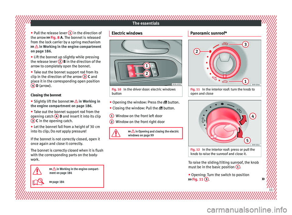
››› page 184 Electric windows
Fig. 10
In the driver door: electric windows
b utt
on ●
Opening the window: Press the butt
on.
● C
losing the window: Pull the button.
W
indow on the front left door
Window on the front right door
››› in Opening and closing the electric
windows on page 99 1
2 Panoramic sunroof*
Fig. 11
In the interior roof: turn the knob to
open and c lo
se Fig. 12
In the interior roof: press or pull the
kno b t
o r
aise the sunroof and close it. To raise the sliding/tilting sunroof, the knob
mu
s
t
be in the basic position 1 .
● Opening: Turn the switch to position
› ›
›
Fig. 11 3 .
» 11
Page 15 of 232
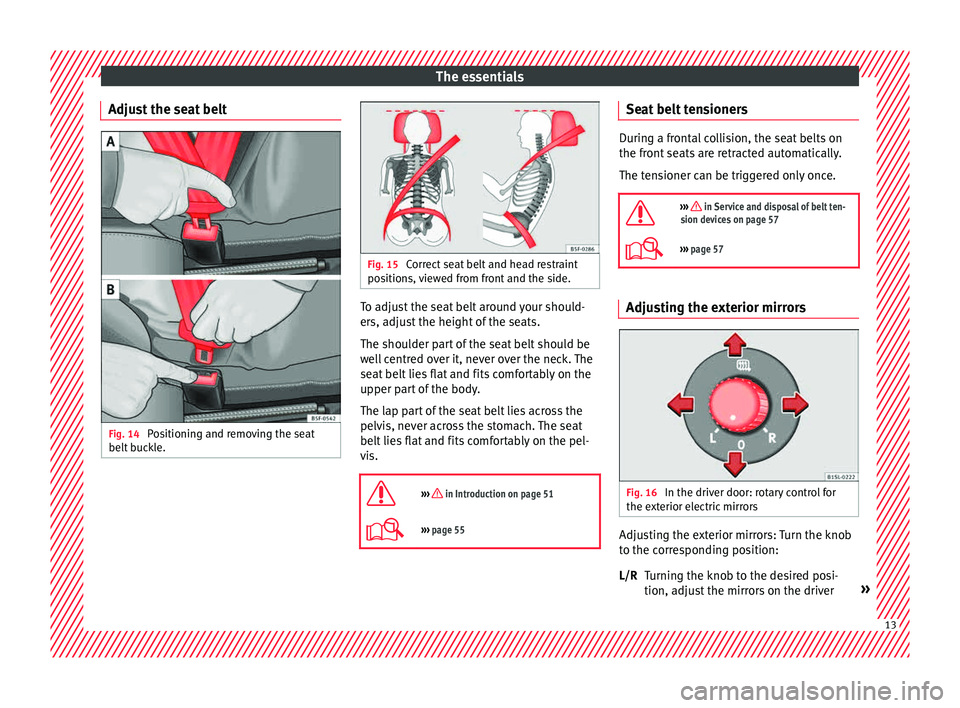
The essentials
Adjust the seat belt Fig. 14
Positioning and removing the seat
belt b
uc
kle. Fig. 15
Correct seat belt and head restraint
pos ition
s, viewed from front and the side. To adjust the seat belt around your should-
er
s, a
dju
st the height of the seats.
The shoulder part of the seat belt should be
well centred over it, never over the neck. The
seat belt lies flat and fits comfortably on the
upper part of the body.
The lap part of the seat belt lies across the
pelvis, never across the stomach. The seat
belt lies flat and fits comfortably on the pel-
vis.
››› in Introduction on page 51
››› page 55 Seat belt tensioners
During a frontal collision, the seat belts on
the front
se
ats are retracted automatically.
The tensioner can be triggered only once.
››› in Service and disposal of belt ten-
sion devices on page 57
››› page 57 Adjusting the exterior mirrors
Fig. 16
In the driver door: rotary control for
the e xt
erior el
ectric mirrors Adjusting the exterior mirrors: Turn the knob
t
o the c
orr
esponding position:
Turning the knob to the desired posi-
tion, adjust the mirrors on the driver »
L/R 13
Page 17 of 232
The essentials
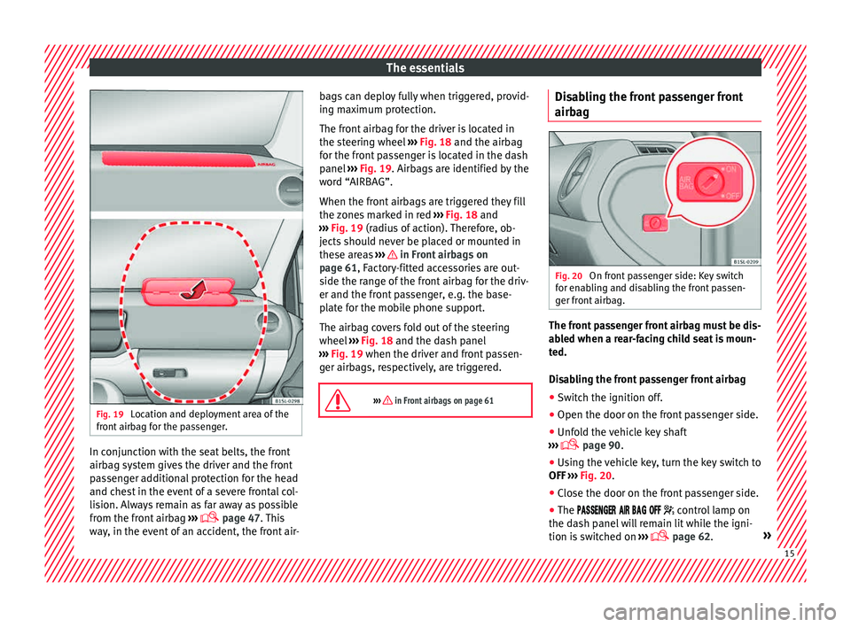
Fig. 19
Location and deployment area of the
fr ont
airb
ag for the passenger. In conjunction with the seat belts, the front
airb
ag sy
s
tem gives the driver and the front
passenger additional protection for the head
and chest in the event of a severe frontal col-
lision. Always remain as far away as possible
from the front airbag ›››
page 47. This
way, in the event of an accident, the front air- bags can deploy fully when triggered, provid-
ing max
imum protection.
The front airbag for the driver is located in
the steering wheel ››› Fig. 18 and the airbag
for the front passenger is located in the dash
panel ››› Fig. 19. Airbags are identified by the
word “AIRBAG”.
When the front airbags are triggered they fill
the zones marked in red ››› Fig. 18 and
››› Fig. 19 (radius of action). Therefore, ob-
jects should never be placed or mounted in
these areas ››› in Front airbags on
p ag
e 61
, Factory-fitted accessories are out-
side the range of the front airbag for the driv-
er and the front passenger, e.g. the base-
plate for the mobile phone support.
The airbag covers fold out of the steering
wheel ››› Fig. 18 and the dash panel
››› Fig. 19 when the driver and front passen-
ger airbags, respectively, are triggered.
››› in Front airbags on page 61 Disabling the front passenger front
airb
ag Fig. 20
On front passenger side: Key switch
f or en
ab
ling and disabling the front passen-
ger front airbag. The front passenger front airbag must be dis-
ab
l
ed when a r
ear-facing child seat is moun-
ted.
Disabling the front passenger front airbag
● Switch the ignition off.
● Open the door on the front passenger side.
● Unfold the vehicle key shaft
›››
page 90.
● Using the vehicle key, turn the key switch to
OFF ›››
Fig. 20.
● Close the door on the front passenger side.
● The
control lamp on
the dash panel will remain lit while the igni-
tion is switched on ›››
page 62. » 15
Page 19 of 232
The essentials
A sticker with important information about
the p a
s
senger airbag is located on the pas- senger's sun visor and/or on the passenger
side door frame.
››› in Important information regarding
the front passenger's airbag on page 64
››› page 63 Mounting systems
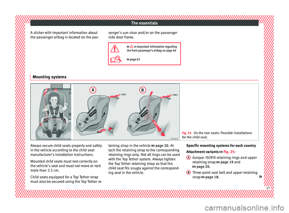
Fig. 25
On the rear seats: Possible installations
for the c hi
ld seat. Always secure child seats properly and safely
in the
v
ehic
le according to the child seat
manufacturer's installation instructions.
Mounted child seats must rest correctly on
the vehicle's seat and must not move or rock
more than 2.5 cm.
Child seats equipped for a Top Tether strap
must also be secured using the Top Tether re- taining strap in the vehicle
››› page 20. At-
tach the retaining strap to the corresponding
retaining rings only. Not all rings can be used
with the Top Tether system. Always tighten
the Top Tether retaining strap so that the
child seat fits snugly against the correspond-
ing seat in the vehicle. Specific mounting systems for each country
Attachment
variants ››› Fig. 25:
Europe: ISOFIX retaining rings and upper
retaining strap ››› page 19 and
››› page 20.
Three-point seat belt and upper retaining
strap ››› page 18. »
A B
17
Page 22 of 232
The essentials
supply volume of the child seat or can be ac-
quir ed at
a
SEAT dealership. If necessary,
these elements are inserted in both anchor
points of the vehicle ››› in Safety instruc-
tion s on p
ag
e 65.
● Observe the manufacturer's instructions
when inst
alling and removing the child seat
››› in Safety instructions on page 65.
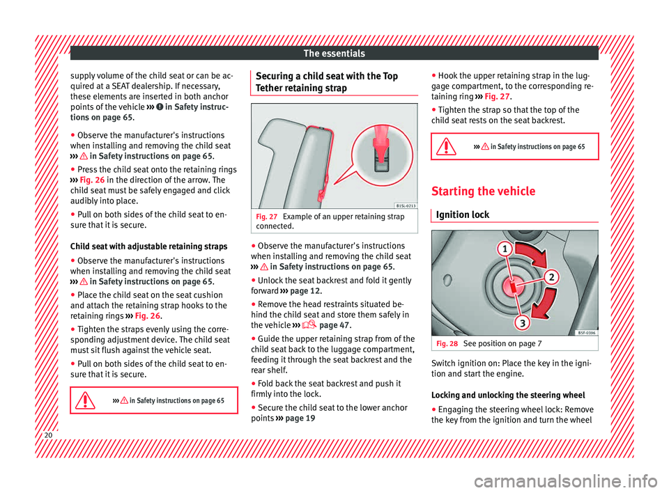
● Press the child seat onto the retaining rings
› ›
›
Fig. 26 in the direction of the arrow. The
child seat must be safely engaged and click
audibly into place.
● Pull on both sides of the child seat to en-
sure th
at it is secure.
Child seat with adjustable retaining straps
● Observe the manufacturer's instructions
when inst
alling and removing the child seat
››› in Safety instructions on page 65.
● Place the child seat on the seat cushion
and att ac
h the r
etaining strap hooks to the
retaining rings ››› Fig. 26.
● Tighten the straps evenly using the corre-
sponding a
djustment device. The child seat
must sit flush against the vehicle seat.
● Pull on both sides of the child seat to en-
sure th
at it is secure.
››› in Safety instructions on page 65 Securing a child seat with the Top
T
ether r
et
aining strap Fig. 27
Example of an upper retaining strap
c onnect
ed. ●
Observe the manufacturer's instructions
when in s
t
alling and removing the child seat
››› in Safety instructions on page 65.
● Unlock the seat backrest and fold it gently
f or
w
ard ››› page 12.
● Remove the head restraints situated be-
hind the chil
d seat and store them safely in
the vehicle ›››
page 47.
● Guide the upper retaining strap from of the
chil
d seat back to the luggage compartment,
feeding it through the seat backrest and the
rear shelf.
● Fold back the seat backrest and push it
firmly int
o the lock.
● Secure the child seat to the lower anchor
points ››
› page 19 ●
Hook the upper r
etaining strap in the lug-
gage compartment, to the corresponding re-
taining ring ››› Fig. 27.
● Tighten the strap so that the top of the
chil
d seat rests on the seat backrest.
››› in Safety instructions on page 65 Starting the vehicle
Ignition lock Fig. 28
See position on page 7 Switch ignition on: Place the key in the igni-
tion and s
t
ar
t the engine.
Locking and unlocking the steering wheel
● Engaging the steering wheel lock: Remove
the key fr
om the ignition and turn the wheel20
Page 35 of 232
The essentials
Emergencies F u
se
s
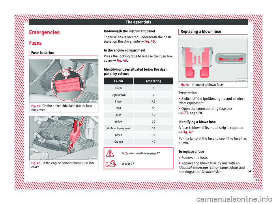
Fuse location Fig. 45
On the driver-side dash panel: fuse
bo x
c
over Fig. 46
In the engine compartment: fuse box
c o v
er Underneath the instrument panel
The f
use bo
x is located underneath the dash
panel on the driver side ››› Fig. 45.
In the engine compartment
Press the locking tabs to release the fuse box
cover ››› Fig. 46.
Identifying fuses situated below the dash
panel by colours
ColourAmp rating
Purple3
Light brown5
Brown7.5
Red10
Blue15
Yellow20
White or transparent25
Green30
Orange40
››› in Introduction on page 77
›››
page 77 Replacing a blown fuse
Fig. 47
Image of a blown fuse Preparation
● Switch off the ignition, lights and all elec-
tric al
equipment
.
● Open the corresponding fuse box
›››
page 78.
Identifying a blown fuse
A fuse is blown if its metal strip is ruptured
››› Fig. 47.
Point a lamp at the fuse to see if the fuse has
blown.
To replace a fuse
● Remove the fuse.
● Replace the blown fuse by one with an
identica
l amperage rating (same colour and
markings) and identical size. » 33
Page 40 of 232
The essentials
●
Only u
se wheel bolts which correspond to
the wheel rims in question.
● Never use different wheel bolts.
● The bolts and threads should be clean, free
of oil
and grease and easy to thread.
● To loosen and tighten the wheel bolts, al-
way
s use the wheel brace supplied with the
vehicle.
● Loosen the wheel bolts only about one turn
before r
aising the vehicle with the jack.
● Never grease or lubricate wheel bolts or the
wheel hub thre
ads. Although they have been
tightened to the prescribed torque, they
could come loose while driving.
● Never loosen the bolted joints of wheel
rims with bo
lted ring trims.
● If the wheel bolts are not tightened to the
correct
torque, they may come loose while
driving, and the bolts and rims may come
out. If the tightening torque is too high, the
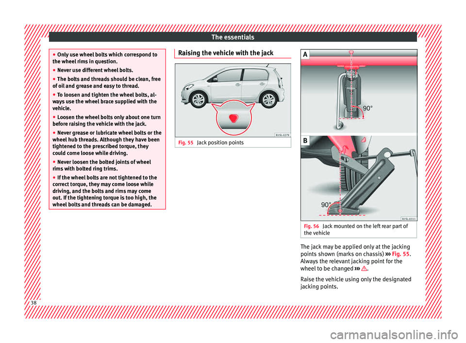
wheel bolts and threads can be damaged. Raising the vehicle with the jack
Fig. 55
Jack position points Fig. 56
Jack mounted on the left rear part of
the v
ehic
le The jack may be applied only at the jacking
points
sho
wn (m
arks on chassis) ››› Fig. 55.
Always the relevant jacking point for the
wheel to be changed ››› .
R ai
se the
vehicle using only the designated
jacking points. 38
Page 41 of 232
The essentials
WARNING
If the vehicle is not correctly raised, it could
fa l
l off the jack causing serious injury. Please
observe the following rules to minimise the
risk of injury:
● You should only use a jack approved by
SEAT f
or your vehicle. Other jacks, even those
approved for other SEAT models, might slip
out of place.
● The ground should be firm and flat. If the
ground i
s sloped or soft then the vehicle
could slip and fall off the jack. If necessary,
support the jack on a wide solid base.
● If the ground is slippery, such as tiles,
plac
e a non-slip surface (a floor mat, for in-
stance) beneath the jack to avoid slipping.
● Only fit the jack at the prescribed jacking
points. The c
law of the jack should grip the
reinforcement nerve on the underbody
››› Fig. 56.
● You should never place a body limb such as
an arm or leg u
nder a raised vehicle that is
solely supported by the jack.
● If you have to work underneath the vehicle,
you mus
t use suitable stands additionally to
support the vehicle, there is a risk of acci-
dent!.
● Never raise the vehicle if it is tilting to one
side or the engine i
s running.
● Never start the engine when the vehicle is
raised.
The vehicle may come loose from the
jack due to the engine vibrations. Removing and fitting a wheel
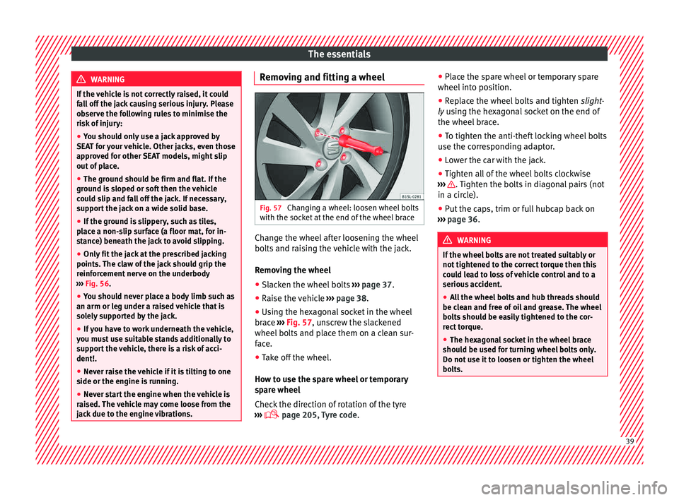
Fig. 57
Changing a wheel: loosen wheel bolts
w ith the soc
k
et at the end of the wheel brace Change the wheel after loosening the wheel
bo
lts
and r
aising the vehicle with the jack.
Removing the wheel
● Slacken the wheel bolts ›››
page 37.
● Raise the vehicle ›››
page 38.
● Using the hexagonal socket in the wheel
brace ›
›› Fig. 57, unscrew the slackened
wheel bolts and place them on a clean sur-
face.
● Take off the wheel.
How to u
se the spare wheel or temporary
spare wheel
Check the direction of rotation of the tyre
››› page 205, Tyre code. ●
Place the s
pare wheel or temporary spare
wheel into position.
● Replace the wheel bolts and tighten slight
-
ly using the hexagonal socket on the end of
the wheel brace.
● To tighten the anti-theft locking wheel bolts
use the corr
esponding adaptor.
● Lower the car with the jack.
● Tighten all of the wheel bolts clockwise
›››
. Tighten the bolts in diagonal pairs (not
in a c ir
c
le).
● Put the caps, trim or full hubcap back on
›››
page 36. WARNING
If the wheel bolts are not treated suitably or
not tight ened t
o the correct torque then this
could lead to loss of vehicle control and to a
serious accident.
● All the wheel bolts and hub threads should
be cle
an and free of oil and grease. The wheel
bolts should be easily tightened to the cor-
rect torque.
● The hexagonal socket in the wheel brace
should be u
sed for turning wheel bolts only.
Do not use it to loosen or tighten the wheel
bolts. 39
Page 44 of 232

The essentials
Driving style
T o
w
ing requires some experience, especially
when using a tow rope. Both drivers should
realise how difficult it is to tow a vehicle. In-
experienced drivers should not attempt to
tow.
Do not pull too hard with the towing vehicle
and take care to avoid jerking the tow rope.
When towing on an unpaved road, there is al-
ways a risk of overloading and damaging the
anchorage points.
Switch on the ignition so that the turn sig-
nals, windscreen wipers and windscreen
washer can work. Ensure that the steering
wheel is unlocked and moves freely.
Place the gear lever in neutral on vehicles
with a manual gearbox. With an automatic
gearbox, place the lever in N.
To brake, press the brake pedal firmly. The
brake servo does not work when the engine
is switched off.
The power steering only works when the igni-
tion is switched on and the vehicle is moving,
provided that the battery is sufficiently charg-
ed. Otherwise, it will need more force.
Ensure that the tow rope remains taut at all
times. ››› in Instructions for tow-starting on
page 75
››› page 74 Tow-starting
In general, the vehicle should not be started
by
t
owing. Jump-starting is much more pref-
erable ››› page 42.
For technical reasons, the following vehicles
can not be tow started:
● Vehicles with an automatic gearbox.
● If the vehicle battery is flat, it is possible
that the en
gine control unit does not operate
correctly.
However, if your vehicle must absolutely be
tow-started (manual gearbox):
● Put it into second or third gear.
● Keep the clutch pressed down.
● Switch on the ignition and the hazard warn-
ing lights.
● Rel
ease the clutch when both vehicles are
movin
g.
● As soon as the engine starts, press the
clutc
h and move the gear lever into neutral.
This helps to prevent a collision with the tow-
ing vehicle. How to jump start
Jump lea
ds If the engine fails to start because of a dis-
ch
ar
ged battery, the battery of another vehi-
cle can be used to start the engine. Before
starting, check the magic eye on the battery
››› page 193.
For starting assistance, jump lead cables con-
forming to the standard DIN 72553 are re-
quired (see the cable manufacturer instruc-
tions). The cable section in vehicles with pet-
rol engine must be at least 25 mm 2
. WARNING
Incorrect use of jump leads and incorrectly
jump st ar
ting could cause the battery to ex-
plode resulting in serious injury. Please ob-
serve the following rules to minimise the risk
of a battery explosion:
● The battery providing current must have
the same v
oltage (12V) and approximately
the same capacity (see markings on battery)
as the flat battery.
● Never charge a frozen or recently thawed
batter
y. A flat battery can also freeze at tem-
peratures close to 0 °C (+32 °F).
● If a battery is frozen and/or has been frozen
then it mus
t be replaced.
● A highly explosive mixture of gases is re-
lea
sed when the battery is being charged. Al-
ways keep lit cigarettes, flames, sparks and 42