radio Seat Mii 2017 Owner's manual
[x] Cancel search | Manufacturer: SEAT, Model Year: 2017, Model line: Mii, Model: Seat Mii 2017Pages: 232, PDF Size: 4.91 MB
Page 89 of 232
General instrument panel
Operation
Gener a
l
instrument panel
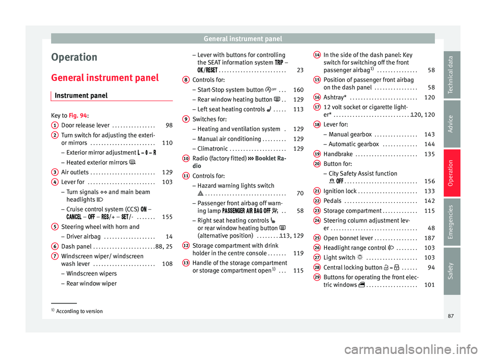
Instrument panel Key to
Fig. 94:
Door rel e
ase lever . . . . . . . . . . . . . . . . 98
Turn switch for adjusting the exteri-
or mirrors . . . . . . . . . . . . . . . . . . . . . . . . 110
– Exterior mirr or a
djustment
– Heated exterior mirrors
Air outlets . . . . . . . . . . . . . . . . . . . . . . . . 129
Lever for . . . . . . . . . . . . . . . . . . . . . . . . . 103
– Turn sign
als and main beam
headlights
– Cruise control system (CCS) –
– – /+ – /- . . . . . . .155
Steering wheel with horn and – Driver airb ag . . . . . . . . . . . . . . . . . . . 14
Da
sh panel . . . . . . . . . . . . . . . . . . . . . . . 88, 25
Windscreen wiper/ windscreen
wash l
ever . . . . . . . . . . . . . . . . . . . . . . . 108
– Wind s
creen wipers
– Rear window wiper
1 2
3
4
5
6
7 –
Lev
er w
ith buttons for controlling
the SEAT information system –
/ . . . . . . . . . . . . . . . . . . . . . . . . . 23
Controls for:
– Start
-Stop system button . . .160
– Rear w
indow heating button . .129
– Left
seat heating controls . . . . . 113
Switches for: – Heating and
ventilation system .129
– Manual air c
onditioning . . . . . . . . . 129
– Clim atr
onic . . . . . . . . . . . . . . . . . . . . . 129
Radio (factory fitted) ›››
Booklet Ra-
dio
Controls for:
– Hazard warning lights switch
. . . . . . . . . . . . . . . . . . . . . . . . . . . . . . 70
– Pa s
senger front airbag off warn-
ing lamp . .58
– Right seat
heating controls
or rear window heating button
(alternative position) . . . . . . . . . . .113, 129
Storage compartment with drink
hol der in the c
entre console . . . . . . .119
Handle of the storage compartment
or stor
age compartment open 1)
. . . 115
8 9
10
11
12
13 In the side of the dash panel: Key
sw
it
c
h for switching off the front
passenger airbag 1)
. . . . . . . . . . . . . . . 58
Position of passenger front airbag
on the dash p
anel . . . . . . . . . . . . . . . . 58
Ashtray* . . . . . . . . . . . . . . . . . . . . . . . . . 120
12 volt socket or cigarette light-
er* . . . . . . . . . . . . . . . . . . . . . . . . . . . . . . . 120, 120
Lever for:
– Manual g
earbox . . . . . . . . . . . . . . . . 143
– Autom atic
gearbox . . . . . . . . . . . . . 144
Handbrake . . . . . . . . . . . . . . . . . . . . . . . 135
Button for:
– City
Safety Assist function
. . . . . . . . . . . . . . . . . . . . . . . . . . . 156
Ignition lock . . . . . . . . . . . . . . . . . . . . . . 133
Pedals . . . . . . . . . . . . . . . . . . . . . . . . . . . 142
Storage compartment . . . . . . . . . . . . .115
Steering column adjustment lev-
er . . . . . . . . . . . . . . . . . . . . . . . . . . . . . . . . 48
Open bonnet lever . . . . . . . . . . . . . . . . 187
Headlight range control . . . . . . . . 103
Light switch . . . . . . . . . . . . . . . . . . . 103
Central locking button . . . . . .94
Buttons for operating the front elec-
tric windo
ws . . . . . . . . . . . . . . . . . . . 101 14
15
16
17
18
19
20
21
22
23
24
25
26
27
28
29
1)
According to version
87
Technical data
Advice
Operation
Emergencies
Safety
Page 94 of 232
Operation
Opening and closing V ehic
l
e key set
Remote control vehicle key* Fig. 96
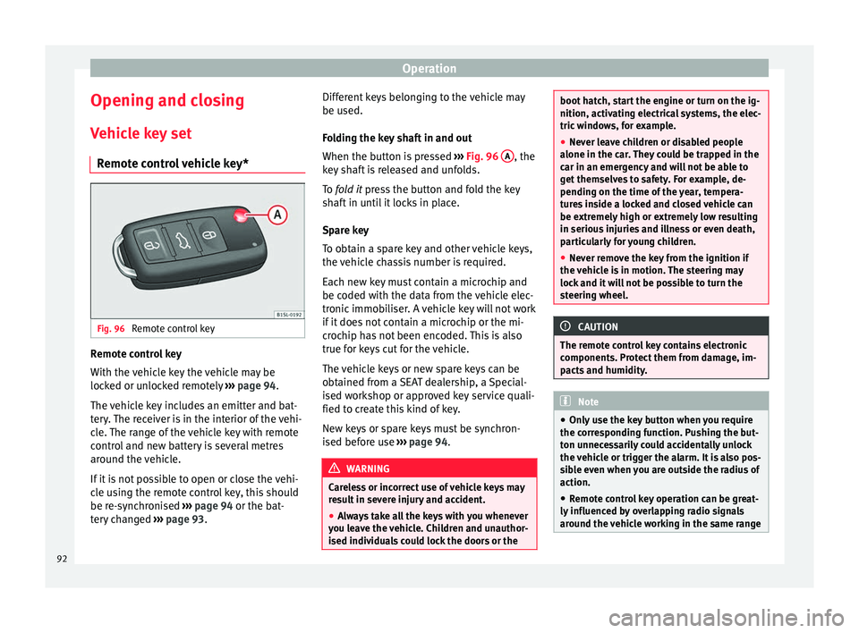
Remote control key Remote control key
W
ith the
v
ehicle key the vehicle may be
locked or unlocked remotely ››› page 94.
The vehicle key includes an emitter and bat-
tery. The receiver is in the interior of the vehi-
cle. The range of the vehicle key with remote
control and new battery is several metres
around the vehicle.
If it is not possible to open or close the vehi-
cle using the remote control key, this should
be re-synchronised ››› page 94 or the bat-
tery changed ››› page 93. Different keys belonging to the vehicle may
be used.
Fo
lding the key shaft in and out
When the button is pressed ››› Fig. 96 A , the
k ey
sh
aft is released and unfolds.
To fold it press the button and fold the key
shaft in until it locks in place.
Spare key
To obtain a spare key and other vehicle keys,
the vehicle chassis number is required.
Each new key must contain a microchip and
be coded with the data from the vehicle elec-
tronic immobiliser. A vehicle key will not work
if it does not contain a microchip or the mi-
crochip has not been encoded. This is also
true for keys cut for the vehicle.
The vehicle keys or new spare keys can be
obtained from a SEAT dealership, a Special-
ised workshop or approved key service quali-
fied to create this kind of key.
New keys or spare keys must be synchron-
ised before use ››› page 94. WARNING
Careless or incorrect use of vehicle keys may
re s
ult in severe injury and accident.
● Always take all the keys with you whenever
you le
ave the vehicle. Children and unauthor-
ised individuals could lock the doors or the boot hatch, start the engine or turn on the ig-
nition, activatin
g el
ectrical systems, the elec-
tric windows, for example.
● Never leave children or disabled people
alone in the car
. They could be trapped in the
car in an emergency and will not be able to
get themselves to safety. For example, de-
pending on the time of the year, tempera-
tures inside a locked and closed vehicle can
be extremely high or extremely low resulting
in serious injuries and illness or even death,
particularly for young children.
● Never remove the key from the ignition if
the vehic
le is in motion. The steering may
lock and it will not be possible to turn the
steering wheel. CAUTION
The remote control key contains electronic
component s. Pr
otect them from damage, im-
pacts and humidity. Note
● Only u
se the key button when you require
the corresponding function. Pushing the but-
ton unnecessarily could accidentally unlock
the vehicle or trigger the alarm. It is also pos-
sible even when you are outside the radius of
action.
● Remote control key operation can be great-
ly influenced b
y overlapping radio signals
around the vehicle working in the same range 92
Page 95 of 232
Opening and closing
of frequencies (for example, radio
tran
smitt
ers, mobile telephones).
● Obstacles between the remote control and
the vehic
le, bad weather conditions and
draining batteries can considerably reduce
the range of the remote control.
● If the buttons of the vehicle key are press-
ed ›››
Fig. 96 or one of the central locking but-
tons ››› page 94 is pressed repeatedly in
quick succession, the central locking briefly
disconnects as protection against overload-
ing. The vehicle is then unlocked. Lock it if necessary. Mechanical vehicle key
Fig. 97
Vehicle mechanical key The vehicle key set may include a mechanical
k
ey
›
›› Fig. 97. Duplicate keys
To obt
ain a spare key and other vehicle keys,
the vehicle chassis number is required.
Each new key must contain a microchip and
be coded with the data from the vehicle elec-
tronic immobiliser. A vehicle key will not work
if it does not contain a microchip or the mi-
crochip has not been encoded. This is also
true for keys cut for the vehicle.
The vehicle keys or new spare keys can be
obtained from a SEAT dealership, a special-
ised workshop or an approved locksmith
qualified to create them.
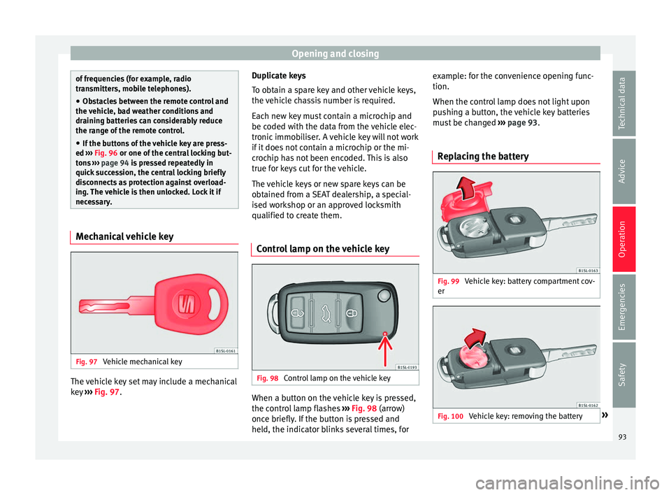
Control lamp on the vehicle key Fig. 98
Control lamp on the vehicle key When a button on the vehicle key is pressed,
the c
ontr
o
l lamp flashes ››› Fig. 98 (arrow)
once briefly. If the button is pressed and
held, the indicator blinks several times, for example: for the convenience opening func-
tion.
When the contro
l lamp does not light upon
pushing a button, the vehicle key batteries
must be changed ››› page 93.
Replacing the battery Fig. 99
Vehicle key: battery compartment cov-
er Fig. 100
Vehicle key: removing the battery » 93
Technical data
Advice
Operation
Emergencies
Safety
Page 121 of 232
Transport and practical equipment
● In fr ont
of
the rear seats ››› Fig. 127.
● Rear shelf for light items of clothing*.
● Bag hook in the luggage compartment
›››
page 123.
● In the upper part of the centre console, in-
ste
ad of the radio ››› Fig. 94 11 .
WARNING
Clothing hung on the coat hooks could re-
strict the driv
er's view and lead to serious ac-
cidents.
● Hang the clothes from the hooks so that
driver's
view is not restricted.
● The coat hook is suitable for light items of
clothing. Nev
er place heavy, hard or sharp
objects in the bags. Drink holders
The drink holders are in the open storage
c
omp
ar
tments in the driver and passenger
doors. WARNING
Improper use of the drink holders can cause
injury .
● Do not
place containers with hot drinks in a
drink hol
der. During sudden braking or driv-
ing manoeuvres, the hot drink could be spil-
led and lead to scalding. ●
Ens ur
e that no bottles or other object are
dropped in the driver footwell, as they could
get under the pedals and obstruct their work-
ing.
● Never place heavy containers, food or other
heavy o
bjects in the drink holder. In the
event of an accident, these heavy objects
could be “thrown around” the vehicle interior
and cause serious injuries. WARNING
Closed bottles inside the vehicle could ex-
p lode or c r
ack due to the heat or the cold.
● Never leave a closed bottle in the vehicle if
the inside t
emperature is too high or too low. CAUTION
Do not leave open drinks containers in the
drink ho l
ders when the vehicle is in motion.
They could spill during braking, for example,
and cause damage to the vehicle and the
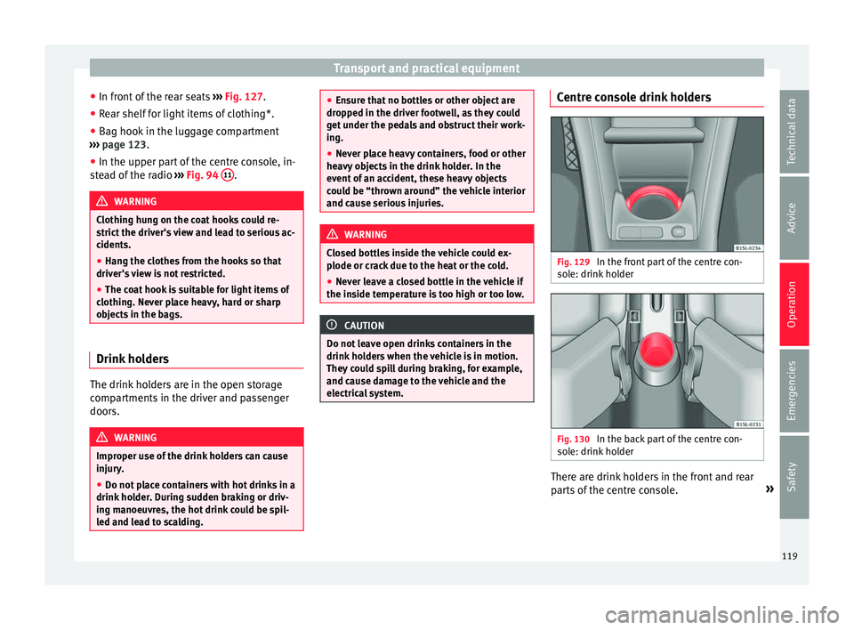
electrical system. Centre console drink holders
Fig. 129
In the front part of the centre con-
so l
e: drink
holder Fig. 130
In the back part of the centre con-
so l
e: drink
holder There are drink holders in the front and rear
p
ar
ts
of the centre console. »
119
Technical data
Advice
Operation
Emergencies
Safety
Page 123 of 232
Transport and practical equipment
All connected appliances should be in per-
f ect
w
orking order without any faults.
Maximum power consumption
Power sock-
etMaximum power consumption
12 Volts120 Watts The maximum capacity of the socket must
not be e
x
ceeded. The power consumption is
indicated on the rating plate of each appli-
ance.
Where 2 or more appliances are connected at
the same time, the total rating of all the con-
nected devices must never exceed 190 Watts
››› .
12 v o
lt
power socket
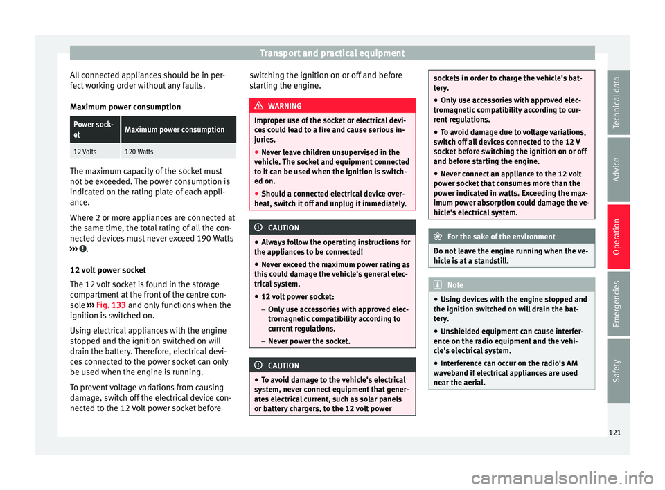
The 12 volt socket is found in the storage
compartment at the front of the centre con-
sole ›››
Fig. 133 and only functions when the
ignition is switched on.
Using electrical appliances with the engine
stopped and the ignition switched on will
drain the battery. Therefore, electrical devi-
ces connected to the power socket can only
be used when the engine is running.
To prevent voltage variations from causing
damage, switch off the electrical device con-
nected to the 12 Volt power socket before switching the ignition on or off and before
star
ting the engine. WARNING
Improper use of the socket or electrical devi-
ce s
could lead to a fire and cause serious in-
juries.
● Never leave children unsupervised in the
vehicl
e. The socket and equipment connected
to it can be used when the ignition is switch-
ed on.
● Should a connected electrical device over-
heat, swit
ch it off and unplug it immediately. CAUTION
● Alw a
ys follow the operating instructions for
the appliances to be connected!
● Never exceed the maximum power rating as
this c
ould damage the vehicle's general elec-
trical system.
● 12 volt power socket:
– Only u
se accessories with approved elec-
tromagnetic compatibility according to
current regulations.
– Never power the socket. CAUTION
● To av oid d
amage to the vehicle's electrical
system, never connect equipment that gener-
ates electrical current, such as solar panels
or battery chargers, to the 12 volt power sockets in order to charge the vehicle's bat-
ter
y
.
● Only use accessories with approved elec-
tromagnetic
compatibility according to cur-
rent regulations.
● To avoid damage due to voltage variations,
switc
h off all devices connected to the 12 V
socket before switching the ignition on or off
and before starting the engine.
● Never connect an appliance to the 12 volt
power soc
ket that consumes more than the
power indicated in watts. Exceeding the max-
imum power absorption could damage the ve-
hicle's electrical system. For the sake of the environment
Do not leave the engine running when the ve-
hicl e i
s at a standstill. Note
● Us in
g devices with the engine stopped and
the ignition switched on will drain the bat-
tery.
● Unshielded equipment can cause interfer-
ence on the ra
dio equipment and the vehi-
cle's electrical system.
● Interference can occur on the radio's AM
wave
band if electrical appliances are used
near the aerial. 121
Technical data
Advice
Operation
Emergencies
Safety
Page 156 of 232
Operation
●
When cl e
aning the sensors with high-pres-
sure or steam cleaning equipment, spray the
sensors briefly at a distance of no less than
10 cm.
● Different sources of noise can produce er-
rors
in the parking distance warning system,
e.g. parking distance warning systems from
other vehicles, inductive loops or construc-
tion works machines.
● Retrofitting of components to the vehicle,
such a
s a bicycle carrier, may interfere with
the function of the parking distance warning
system. Parking distance warning system
Fig. 151
Parking distance warning system
sen sor
s
on the rear bumper The sensors of the parking distance warning
sy
s
t
em are situated on the rear bumper
››› Fig. 151. Switching the parking distance warning sys-
tem on and off
●
Swit
ching on: With the ignition swit
ched
on, select reverse gear. A short audible warn-
ing confirms that the parking distance warn-
ing system is switched on and functioning.
● Switching off: Rele
ase reverse gear.
Special features of the parking distance
warning system
● The parking distance warning system
sometimes r
egisters water on the sensors as
an obstacle.
● If the distance does not change, the warn-
ing sign
al will sound less loudly after a few
seconds. If the continuous signal sounds, the
volume will remain constant.
● When the vehicle moves away from the ob-
stac
le, the beeping sound automatically
switches off. When getting close again, it re-
connects.
● Your SEAT dealership can adjust the volume
of the warnin
g signals. Note
A fault in the parking distance warning sys-
tem i s
indicated through a brief audible warn-
ing that is constant for about 3 seconds when
switching it on the first time. Check the park-
ing distance warning system at a Specialised
workshop as soon as possible. Optical parking system* (OPS)
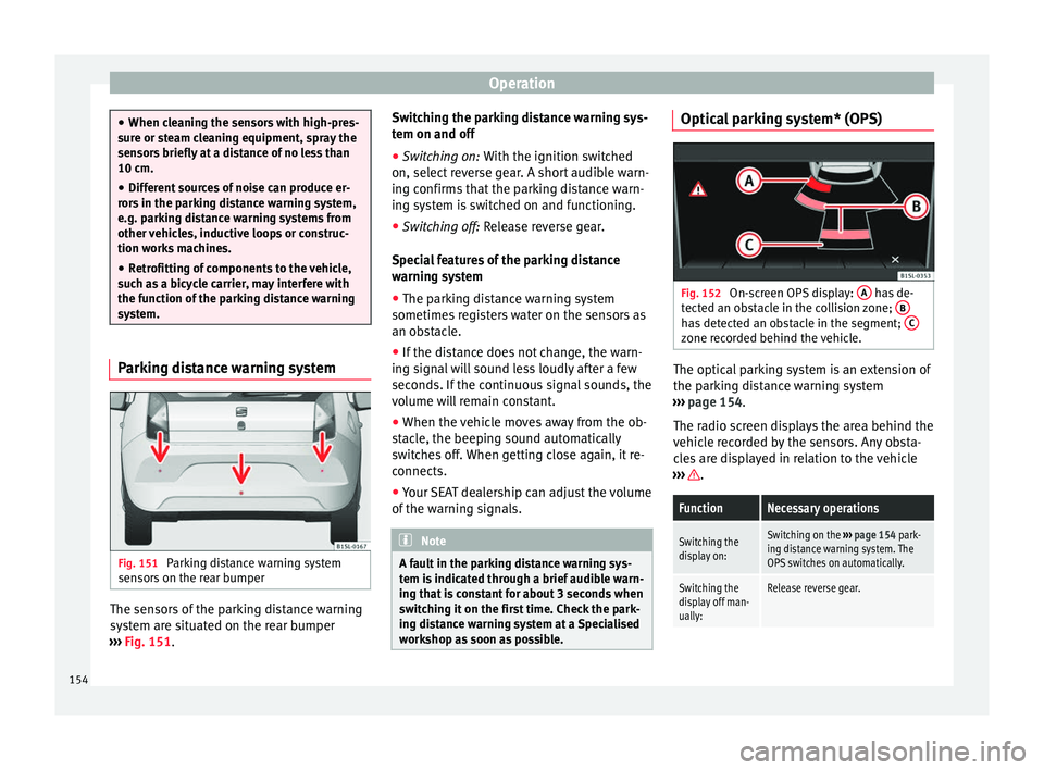
Fig. 152
On-screen OPS display: A has de-
tect ed an o
bstacle in the collision zone; B has detected an obstacle in the segment;
C zone recorded behind the vehicle.
The optical parking system is an extension of
the p
ark
in
g distance warning system
››› page 154.
The radio screen displays the area behind the
vehicle recorded by the sensors. Any obsta-
cles are displayed in relation to the vehicle
››› .
FunctionNecessary operations
Switching the
display on:Switching on the
››› page 154 park-
ing distance warning system. The
OPS switches on automatically.
Switching the
display off man-
ually:Release reverse gear. 154
Page 157 of 232
Driver assistance systems
Zones explored
B ehind the
v
ehicle ››› Fig. 152 C , the zone
an aly
sed r
eaches a distance of up to 150 cm
and around 60 cm to the sides.
Screen display
The image displayed represents the super-
vised zones in several segments. As the vehi-
cle moves closer to an obstacle, the segment
moves closer to the vehicle displayed A or
B . When the penultimate segment is dis-
p l
a
yed, this means that the vehicle has
reached the collision zone. Stop the vehicle!
Distance from
the vehicle to
the obstacleAudible
warning
Displayed in col-
our on the screen: colour of the seg-ment if an obsta-cle is recognised
behind:
approx. 31-150
cmbeeping soundYellow
behind:
approx. 0-30 cmperma- nent
soundRed WARNING
Do not be distracted from traffic to look at the
sc r
een. Note
● SEA T r
ecommends practising using the
parking distance warning system in a traffic-
free zone or in a car park to familiarise your-
self with the system and its operation.
● The display on the radio screen of the area
explor
ed by the sensors may take up to 5 sec-
onds. Cruise control* (Cruise control
sys
t
em - CCS)
Control lamp
It lights upPossible cause
This cruise control system maintains the
set speed of the vehicle.
Several warning and control lamps light up
f
or a f
ew sec
onds when the ignition is switch-
ed on, signalling that the function is being
verified. They will switch off after a few sec-
onds. WARNING
If the warning lamps are ignored, the vehicle
ma y
stall in traffic, or may cause accidents
and severe injuries.
● Never ignore the warning lamps. CAUTION
Failure to heed the warning lamps when they
appe ar m
ay result in faults in the vehicle. Cruise control operation
Read the additional information carefully
›› ›
page 24
The cruise control system (CCS) is able to in-
dividually maintain the set speed when driv-
ing forwards from approx. 20 km/h (15 mph).
The CCS only slows down by reducing the ac-
celerator but not by braking ››› .
T r
av
elling down hills with the CCS
When travelling down hills the CCS cannot
maintain a constant speed. Slow the vehicle
down using the brake pedal and reduce
gears if required.
Automatic off
The cruise control system (CCS) is switched
off automatically or temporarily:
● If the system detects a fault that could af-
fect the w
orking order of the CCS.
● If you increase the stored speed by press-
ing the acc
elerator pedal for a certain time.
● If the brake pedal is pressed. »
155
Technical data
Advice
Operation
Emergencies
Safety
Page 168 of 232
Advice
●
All
repairs and modifications to the vehicle
should only be performed by a specialised
workshop. Repairs and malfunctions in the air-
bag sy
s
tem When performing repairs and technical mod-
ification
s,
SEAT's directives must be ob-
served! ››› Modifications and repairs to the front bump-
er
, door
s, fr
ont seats, and repairs to the roof
or chassis should only be carried out in a
specialised workshop. These components
may contain parts or sensors belonging to
the airbag system.
If work is carried out on the airbag system or
parts have to be removed and fitted on the
system when performing other repair work,
parts of the airbag system may be damaged.
The consequence may be that, in the event of
an accident, the airbag inflates incorrectly or
does not inflate at all.
So that the effectiveness of the airbag is not
reduced and that removed parts do not cause
any injuries or environmental pollution, regu-
lations must be observed. These require-
ments are known to specialised workshops.
Modifications to the vehicle suspension may
affect the operation of the airbag system in
the event of collision. For example, if wheel and tyre combinations not approved by SEAT
are used, or if
the vehicle height is lowered,
the suspension is stiffened or the suspension
springs, telescopic arms, dampers, etc., are
modified, the results received by the airbag
sensors and sent to the control unit may not
be accurate. For example, some modifica-
tions to the suspension could increase the
force measured by the sensors and result in
the triggering of the airbag systems in colli-
sions. Under normal conditions, the meas-
ured values would be lower and the airbag
would not have been triggered. Other modifi-
cations may reduce the forces measured by
the sensors and prevent the airbags from be-
ing triggered when they should. WARNING
Repairs or modifications which are not per-
formed c orr
ectly may result in damage or er-
rors in the vehicle operation, affecting the ef-
fectiveness of the airbag systems. This could
result in serious or fatal accidents.
● All repairs and modifications to the vehicle
should on
ly be performed by a specialised
workshop.
● Airbag modules must never be repaired: if
damag
ed, they must be replaced.
● Never fit recycled or reused airbag compo-
nents in
your vehicle. WARNING
Modifications to the vehicle suspension, in-
cludin g the u
se of unauthorised wheel and
tyre combinations, may affect the perform-
ance of the airbags and increase the risk of
serious or fatal injury in the event of acci-
dent.
● Never fit suspension components which are
not identica
l to the original parts in the vehi-
cle.
● Never use wheel and tyre combinations not
appro
ved by SEAT. Retrofitting of mobile phones
An exterior aerial is required for the use of
tw
o-w
a
y radios in the vehicle.
The retro-fitting of electrical or electronic ap-
pliances in the vehicle is subject to their ap-
proval for use in your vehicle. Under certain
circumstances, this could mean that your ve-
hicle registration documents are no longer
valid.
SEAT has approved your vehicle for use with
two-way radios providing the following condi-
tions are observed:
● The exterior aerial must be mounted pro-
fes
sionally.
● The maximum transmitting power is 10
watts.
166
Page 169 of 232
Care and maintenance
The optimal reach of the equipment is only
ac hiev
ed w
ith an external aerial.
Check first with a specialised workshop that
understands the technical possibilities of in-
stallation if you wish to use a two-way radio
with a transmitting power of over 10 watts.
SEAT recommends taking your car in for tech-
nical service.
All legal requirements, together with the in-
structions for the use of two-way radios must
be observed. WARNING
If the two-way radio is not securely fastened
in pos ition, it
could be sent flying around the
vehicle in the event of sharp braking, sudden
manoeuvres or accident, causing injury.
● While driving, two-way radios must be se-
curely
fastened in position, outside the air-
bags deployment zones, or safely stowed
away. WARNING
When using a two-way radio without a con-
nection to an e xt
erior aerial, the maximum
permitted levels of electromagnetic radiation
may be exceeded. This is also the case if the
aerial has not been correctly installed.
● You should only use a two-way radio inside
the vehic
le if it has first been correctly con-
nected to an exterior aerial. Information stored by the control
u
nit
s Your vehicle is fitted at the factory with a ser-
ies
of
electronic control units responsible for
the engine and gearbox management. In ad-
dition, the control units supervise the per-
formance of the exhaust gas system and the
airbag systems.
Therefore, while the vehicle is being driven,
these electronic control units are continuous-
ly analysing the vehicle data. In the event of
faults or deviations from the theoretical val-
ues, only this data is stored. Normally, the
warning lamps on the instrument panel light
up in the event of faults.
This data can only be read and analysed us-
ing special equipment.
The storing of the data allows specialised
workshops to detect and repair faults. Stored
data may include:
● Data relating to the engine or the gearbox
● Speed
● Direction of travel
● Braking force
● Detection of seat belt
The v ehic
le control units never record conver-
sations held by passengers in the vehicle.
In vehicles equipped with an emergency call
function via the mobile phone or other appli- ances connected in the vehicle, it is possible
to send the v
ehicle position. If the control
unit records an accident with airbag activa-
tion, the system may automatically send a
signal. This will depend on the network oper-
ator. Normally, transmission is only possible
in areas with good coverage.
Event Data Recorder
The vehicle is not fitted with an event data re-
corder.
An event data recorder temporarily stores the
vehicle information. Therefore, in the event of
an accident, it is possible to obtain detailed
information about how the accident occur-
red. Vehicles with airbag systems can store
data relating to impact speed, seat belt sta-
tus, seat positions and airbag activation
times may be stored, etc. The volume of data
depends on the manufacturer.
Event data recorders can only be mounted
with authorisation from the vehicle owner
and, in some countries, they are governed by
local legislation.
Reprogramming control units
On the whole, all the data required for the
component management is stored in the con-
trol units. The programming of certain con-
venience functions, such as the turn signals,
individual door opening and instructions on
the display can be modified using special »
167
Technical data
Advice
Operation
Emergencies
Safety
Page 170 of 232
Advice
equipment at the workshop. If the comfort
f u
nction
s are reprogrammed, the information
and Instruction Manual descriptions will not
coincide with the modified functions. There-
fore, SEAT recommends that any modifica-
tions be recorded in the section “Other work-
shop notes” in the Maintenance Programme.
The SEAT Official Service must have a record
of any modification to the programming.
Reading the vehicle fault memory
There is a diagnostics connector in the vehi-
cle interior for reading the vehicle fault mem-
ory. The fault memory documents errors and
deviations from the theoretical values of the
electronic control units.
The diagnostics connector is in the driver
side footwell area, next to the lever for open-
ing the bonnet, below a cover.
The fault memory should only be read and re-
set by a specialised workshop.
Using a mobile telephone in a vehicle
without c
onnection to an exterior aer-
ial Mobile telephones transmit and receive radio
w
av
e
s also called high-frequency energy,
both when in use and when on stand-by. Sci-
entific studies state that radio waves exceed-
ing certain values may be harmful to the hu- man body. International committees and au-
thorities h
ave established limits and direc-
tives in order to ensure electromagnetic radi-
ation from mobile phones remains within cer-
tain limits that do not endanger health. Nev-
ertheless, there is no conclusive scientific
evidence that wireless telephones are totally
safe.
That is why some experts recommend moder-
ate use of the mobile telephone, and the ap-
pliance of measures to reduce radiation on
the human body.
When a mobile phone not connected to an
exterior aerial is used inside the vehicle, the
electromagnetic radiation may be greater
than if the mobile phone were connected to a
built-in aerial or to another exterior aerial.
If the vehicle is fitted with a suitable hands-
free device that allows the employment of
numerous additional mobile telephone func-
tions with compatible Bluetooth technolo-
gy ®
, it will comply with the legislation in
many countries which only permits the use of
mobile phones inside vehicles using a
hands-free device.
Mobile telephones must be placed in a suita-
ble telephone support or stored safely in the
vehicle. If a support is used for the tele-
phone, it must be securely fastened to the
base plate. The mobile will be secure on the
instrument panel and always within reach of
the driver only by following these procedures. Mobile telephone connection with an exter-
nal aeri
al is carried out subject to the hands-
free device, via the telephone support or by
the Bluetooth ®
connections present in the
mobile telephone and the vehicle.
If the mobile phone is connected to an aerial
incorporated into the vehicle or an exterior
aerial connected to the vehicle, it will help re-
duce the electromagnetic radiation transmit-
ted and the risk to human health. It will also
improve the quality of the connection.
If the phone is used inside the vehicle with-
out the hands-free system, it will not be se-
curely fastened and will not be connected to
the exterior aerial of the vehicle telephone.
Nor will the telephone charge if it is not on
the support. In addition, some calls may
break off and the quality of the connection
will be affected.
Mobile telephones should only be used in-
side the vehicle if they are connected to a
hands-free system. SEAT recommends using
an external aerial should you wish to use a
mobile telephone inside the vehicle.
Bluetooth ®
is a registered trademark of Blue-
tooth ®
SIG, Inc. WARNING
If the mobile phone is not securely fastened
in pos ition, it
could be sent flying around the
vehicle in the event of sharp braking, sudden
manoeuvres or accident, causing injury. 168