check engine light Seat Toledo 2015 User Guide
[x] Cancel search | Manufacturer: SEAT, Model Year: 2015, Model line: Toledo, Model: Seat Toledo 2015Pages: 248, PDF Size: 5.06 MB
Page 167 of 248
Driving
ahead. The braking effect achieved in this
w a
y
helps to reduce the wear of brakes and
tyres; emissions and fuel consumption are
reduced to zero (disconnection due to iner-
tia).
Change gear early to save energy
An effective way of saving fuel is to change
up quickly through the gears. Running the
engine at high rpm in the lower gears uses
an unnecessary amount of fuel.
Manual gearbox: shift up from first to second
gear as soon as possible. We recommend
that, whenever possible, you change to a
higher gear upon reaching 2000 rpm. Follow
the “recommended gear” indication that ap-
pears on the instrument panel
››› page 24.
Avoid driving at high speed
We advise you not to drive at the top speed
permitted by the vehicle. Fuel consumption,
exhaust emissions and noise levels all in-
crease very rapidly at higher speeds. Driving
at moderate speeds will help to save fuel.
Avoid idling
It is worthwhile switching off the engine
when waiting in a traffic jam, at level cross-
ings or at traffic lights with a long red phase.
The fuel saved after only 30 - 40 seconds is greater than the amount of fuel needed to re-
star
t the engine.
The engine takes a long time to warm up
when it is idling. Mechanical wear and pollu-
tant emissions are also especially high dur-
ing this initial warm-up phase. It is therefore
best to drive off immediately after starting
the engine. Avoid running the engine at high
speed.
Periodic maintenance
Periodic maintenance work guarantees that,
before beginning a journey, you will not con-
sume more than the required amount of fuel.
A well-serviced engine gives you the benefit
of improved fuel efficiency as well as maxi-
mum reliability and an enhanced resale val-
ue.
A badly serviced engine can consume up to
10% more fuel than necessary.
Avoid short journeys
To reduce the consumption and emission of
polluting exhaust gases, the engine and the
exhaust gas filtration systems should reach
the optimum operating temperature.
With the engine cold, fuel consumption is
proportionally higher. The engine does not
warm up and fuel consumption does not nor-
malise until having driven approximately four
kilometres (2.5 miles). This is why we recom- mend avoiding short trips whenever possi-
ble.
M
aintain the correct tyre pressures
Bear in mind that keeping the tyres at an ad-
equate pressure saves fuel. If the tyre pres-
sure is just one bar (14.5 psi/100 kPa) too
low, fuel consumption can increase by as
much as 5%. Due to the greater rolling resist-
ance, under-inflation also increases tyre wear
wear and impairs handling.
The tyre pressures should always be checked
when the tyres are cold.
Do not use winter tyres all year round as they
increase fuel consumption by up to 10%.
Avoid unnecessary weight
Given that every kilo of extra weight will in-
crease the fuel consumption, it is advisable
to always check the luggage compartment to
make sure that no unnecessary loads are be-
ing transported.
A roof rack is often left in place for the sake
of convenience, even when it is no longer
needed. At a speed of 100 km/h (62 mph)
and 120 km/h (75 mph) your vehicle will use
about 12% more fuel as a result of the extra
wind resistance caused by the roof rack even
when it is not in use. »
165
Technical data
Advice
Operation
Emergencies
Safety
Page 186 of 248
OperationSTART MANUALLYStart the engine manually
WARNING
● If the en gine i
s switched off, neither the
brake servo nor the power steering will work.
● Do not move the vehicle when the engine is
switc
hed off. CAUTION
Switch off the Start-Stop system ›››
page 166
before driving through a pool of water on the
road. Note
● The batt er
y temperature may reflect
changes in outside temperature after several
hours. If the vehicle has been stopped out-
side at temperatures below zero or in direct
sunlight, for example, the battery tempera-
ture may take several hours to reach the val-
ues required for the correct operating of the
Start-Stop system.
● If the Climatronic system is operating auto-
matica
lly, this could impair automatic engine
shut down under certain conditions. Tiredness detection (break rec-
ommend
ation)*
Intr oduction The Tiredness detection informs the driver
when their drivin
g beh
aviour shows signs of
fatigue. WARNING
Do not let the comfort afforded by the Tired-
nes s
detection system tempt you into taking
any risks when driving. Take regular breaks,
sufficient in length when making long jour-
neys.
● The driver always assumes the responsibil-
ity of driv
ing to their full capacity.
● Never drive if you are tired.
● The system does not detect the tiredness of
the driver in al
l circumstances. Consult the in-
formation in the section ››› page 185, System
limitations.
● In some situations, the system may incor-
rectly int
erpret an intended driving manoeu-
vre as driver tiredness.
● No warning is given in the event of the ef-
fect c
alled microsleep!
● Please observe the indications on the in-
strument p
anel and act as is necessary. Note
● Tiredne s
s detection has been developed for
driving on motorways and well paved roads
only.
● If there is a fault in the system, have it
check
ed by a specialised workshop. Function and operation
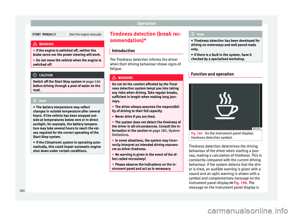
Fig. 194
On the instrument panel display:
tir edne
s
s detection symbol. Tiredness detection determines the driving
beh
av
iour of
the driver when starting a jour-
ney, making a calculation of tiredness. This is
constantly compared with the current driving
behaviour. If the system detects that the driv-
er is tired, an audible warning is given with a
sound and an optic warning is shown with a
symbol and complementary message on the
instrument panel display ››› Fig. 194. The
message on the instrument panel display is
184
Page 188 of 248
Operation
Trailer weight Trailer weight
The comb
ined
vehicle and trailer must be
balanced. To do so use the maximum permit-
ted towing bracket load. An insufficient
weight exerted by the trailer drawbar on the
ball joint of the towing bracket will have a
negative impact upon the response of the ve-
hicle-trailer assembly on the road.
Weight distribution
Distribute loads in the trailer so that heavy
objects are as near to the axle as possible.
Ensure that the objects do not move.
If the towing vehicle is empty and the trailer
loaded then the load distribution is incorrect.
However, if these conditions cannot be avoi-
ded, drive very slowly.
Tyre pressure values
Correct the tyre pressure in your vehicle to
“total load” ›››
page 216, Useful life of tyres .
Trailer weight
Never exceed the authorised trailer weight
under any circumstances ›››
page 221, Tech-
nical specifications .
The trailer weights listed are only applicable
for altitudes up to 1000 m above sea level.
Due to lower air density, engine power de-
creases depending on the increase in alti- tude, this also reduces climbing ability,
which r
equir
es a reduction of the weight of
the vehicle with a trailer by 10% for every
1000 m increase in altitude. The weight of
the assembly is calculated by adding the ve-
hicle weight (loaded) to the trailer weight
(loaded). Always drive with special care when
towing a trailer.
The towed load and support load information
that is displayed on the towing bracket man-
ufacturers label are only values for the verifi-
cation of the device. The correct figures for
your specific vehicle, which are usually lower
than these figures, are given in the documen-
tation of your vehicle. WARNING
● Exc eedin
g the maximum established load
per axle and the maximum towing bracket
load in addition to the maximum permitted
load or the load of the vehicle + trailer as-
sembly can cause accidents and serious inju-
ries.
● A sliding load can considerably affect the
stab
ility and safety of the vehicle + trailer as-
sembly, resulting in accidents and serious in-
juries. Driving with a trailer
Exterior mirrors
Check
whether
you can see enough of the
road behind the trailer with the standard rear
vision mirrors. If this is not the case, you
should have additional exterior mirrors fitted.
Observe the relevant statutory requirements
of the country you are in.
Headlights
Before starting a journey, also check the
headlight beam settings with the trailer
hitched up. Adjust the headlight range set-
tings if necessary ›››
page 122, Main light
range control .
Driving speed
For your own safety do not drive faster than
the maximum permitted speed indicated on
the trailer.
At all times, immediately reduce speed if you
detect the slightest swaying movement of the
trailer. Never try to “return the trailer to a
straight position” by accelerating.
Brakes
Brake in due course! If the trailer has an over-
run brake, apply the brakes gently at first and
then, firmly. This will prevent the jerking that
can be caused by locking of trailer wheels.
Change to a lower gear in good time before
186
Page 189 of 248
Towing bracket device
descending a slope in order to take advant-
ag e of
the en
gine brake.
The trailer is incorporated into the vehicle's
anti-theft alarm system:
● When the vehicle has a factory-fitted anti-
theft al
arm and a towing bracket.
● When the trailer is electrically connected to
the vehic
le via the towing bracket socket.
● When the vehicle electrical device and the
tow
ing bracket are operational.
● When the vehicle is locked and the vehi-
cle's
anti-theft alarm device is activated.
Once the electrical connection is interrupted
with the vehicle trailer locked, the alarm
sounds.
Always switch off the vehicle anti-theft alarm
device before connecting or disconnecting a
trailer. The vehicle anti-theft alarm device
could cause the alarm to sound ››› page 117,
Anti-theft alarm system*.
Engine overheating
In the event that the coolant temperature
gauge needle moves to the right section of
the scale or to the red area, immediately re-
duce speed. If the control lamp flashes on
the general instrument panel, stop the vehi-
cle and switch off the engine. Wait several
minutes and check the coolant level in the
tank ››› page 208. Please observe the following indications
›››
page 100, Coolant level and temperature
.
The coolant temperature can be reduced by
switching on the heating. WARNING
● Adjus t
your speed to suit the road and traf-
fic conditions.
● An electrical installation that is connected
incorrectly
or by non-specialised personnel
can prevent the connection of the current to
the trailer and cause faults in the operation of
the electrical system throughout the entire
vehicle, leading to accidents and serious in-
jury.
● All electrical work must be carried out only
by s
pecialised services.
● Never directly connect the trailer electrical
device t
o the electrical sockets of the reverse
driving lights or other sources of electrical
current. CAUTION
● Av oid c
orners, and sudden and sharp brak-
ing.
● Once the trailing arm has been removed,
plac
e the corresponding cover on the hole of
the fastening point. This prevents dirt from
entering the hole – see the trailer system as-
sembly manual. Note
● In the event of
frequent journeys with a
trailer, we recommend also having the vehi-
cle inspected in between the service inter-
vals.
● When connecting and disconnecting the
trail
er, the handbrake must be applied.
● For technical reasons, trailers with LED re-
verse light
s cannot be incorporated into the
vehicle anti-theft alarm system. Towing bracket device for trail-
er
Intr oduction If the vehicle is equipped with a towing
br
ac
k
et device from the factory or is a genu-
ine SEAT accessory, it meets all national tech-
nical and legal requirements for towing.
Your vehicle is fitted with a 13-pin power
socket for the electrical connection between
the trailer and the vehicle. If the towing
bracket is equipped with a 7-pin connector,
you can use the corresponding available
adaptor that is a genuine SEAT accessory.
The towing device has a maximum vertical
load of 50 kg. »
187
Technical data
Advice
Operation
Emergencies
Safety
Page 200 of 248
Advice
WARNING
Moisture, ice and road salt may affect braking
efficiency . Ri
sk of accident! CAUTION
Heavy dirt on the wheels could lead to their
mis a
lignment. This could result in vibrations
being transmitted to the steering wheel that
under certain conditions may cause prema-
ture steering wear. This dirt must be re-
moved. Note
We recommend you leave paint damage re-
pair s
to a SEAT Authorised Service. Vehicle underbody protection
The underside of the vehicle is coated to per-
m
anently
pr
otect it from chemical and me-
chanical agents.
Given that damage to the protective coating
during driving cannot be completely ruled
out, we recommend you check the condition
of the protective coating on the underbody
and suspension at regular intervals, prefera-
bly before the start and end of the coldest
season of the year.
Authorised SEAT dealers have suitable spe-
cial products and the necessary facilities and are aware of the techniques required for their
applic
ation. We therefore recommend all
touch-up work or additional anti-corrosion
measures be performed by an authorised
SEAT dealer. WARNING
Do not apply underseal or anti-corrosion
co atin
gs to the exhaust pipes, catalytic con-
verter, particulate filter or heat shields on the
exhaust system. Once the engine has
reached operating temperature, these sub-
stances could catch fire. Risk of fire! Cavity waxing
All cavities on the vehicle exposed to corro-
s
ion ar
e perm
anently factory-protected by a
wax solution .
This wax solution does not need to be
checked or touched up. Should wax run out
of the cavities at high ambient temperatures,
remove it using a plastic scraper and clean
away any stains using lighter fluid. WARNING
Note the regulations concerning safety and
env ir
onmental protection if you use lighter
fluid to remove the wax. Risk of fire! Leatherette and upholstery
Leatherette can be cleaned with a damp
cloth. If
thi
s is not sufficient, these parts
should only be cleaned with solvent-free
plastic care and cleaning products .
Textile covers and trim parts on doors, boot
lid, etc. can be cleaned with special deter-
gents, e.g. dry foam. A soft sponge or brush
or a micro-fibre cloth for normal cleaning can
be used. Use special products to clean the
headliner.
The dye used in many garments, for example
dark jeans, is not always sufficiently colour-
fast. Seat upholstery (fabric and leather), es-
pecially when light-coloured, may visibly dis-
colour if the dye comes out of clothing, even
in normal conditions. This is not an uphols-
tery defect but indicates that the dye in the
item of clothing is not solid enough.
Heated seat upholstery Do not clean the seat upholstery with
damp
pr oduct
s, as this could damage the seat
heating system.
Clean the upholstery with special products,
e.g. dry foam, etc.
198
Page 203 of 248
Checking and refilling levels
– Chec k
th
at the fuel flap is correctly closed.
Vehicles with a keyless fuel cap (the side
flap will unlock using the central locking sys-
tem)
– Once the vehicle has been unlocked using
the central
locking button, press the fuel
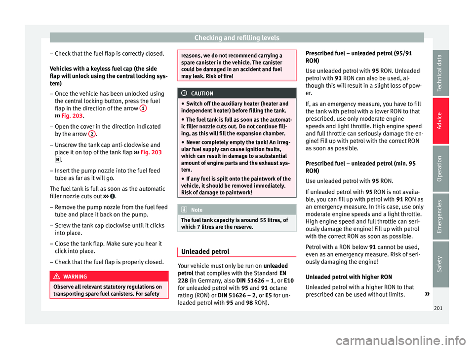
flap in the direction of the arrow 1›››
Fig. 203.
– Open the cover in the direction indicated
by
the arr
ow 2 .
– Unscrew the tank cap anti-clockwise and
pl
ac
e it on top of the tank flap ››› Fig. 203
.
– Insert the pump nozzle into the fuel feed
tube as
far as it will go.
The fuel tank is full as soon as the automatic
filler nozzle cuts out ››› .
– Remove the pump nozzle from the fuel feed
tube and p
l
ace it back on the pump.
– Screw the tank cap clockwise until it clicks
into pl
ace.
– Close the tank flap. Make sure you hear it
click
into place.
– Check that the fuel flap is properly closed. WARNING
Observe all relevant statutory regulations on
tran s
porting spare fuel canisters. For safety reasons, we do not recommend carrying a
sp
ar
e canister in the vehicle. The canister
could be damaged in an accident and fuel
may leak. Risk of fire! CAUTION
● Sw itc
h off the auxiliary heater (heater and
independent heater) before filling the tank.
● The fuel tank is full as soon as the automat-
ic fil
ler nozzle cuts out. Do not continue fill-
ing, as this will fill the expansion chamber.
● Never completely empty the tank! An irreg-
ular f
uel supply can cause ignition faults,
which can result in damage to a substantial
amount of engine parts and the exhaust sys-
tem.
● If any fuel is spilt onto the paintwork of the
vehicl
e, it should be removed immediately.
Risk of damage to paintwork! Note
The fuel tank capacity is around 55 litres, of
which 7 litr e
s are the reserve. Unleaded petrol
Your vehicle must only be run on
un
l
eaded
petrol that complies with the Standard EN
228 (in Germany, also DIN 51626 – 1, or E10
for unleaded petrol with 95 and 91 octane
rating (RON) or DIN 51626 – 2, or E5 for un-
leaded petrol with 95 and 98 RON). Prescribed fuel – unleaded petrol (95/91
RON)
Use un
leaded petrol with 95 RON. Unleaded
petrol with 91 RON can also be used, al-
though this will result in a slight loss of pow-
er.
If, as an emergency measure, you have to fill
the tank with petrol with a lower RON to that
prescribed, use only moderate engine
speeds and light throttle. High engine speed
and full throttle can seriously damage the en-
gine! Fill up with petrol with the correct RON
as soon as possible.
Prescribed fuel – unleaded petrol (min. 95
RON)
Use unleaded petrol with 95 RON.
If unleaded petrol with 95 RON is not availa-
ble, you can fill up with petrol with 91 RON as
an emergency measure. In this case, use only
moderate engine speeds and a light throttle.
High engine speed and full throttle can seri-
ously damage the engine! Fill up with petrol
with the correct RON as soon as possible.
Petrol with a RON below 91 cannot be used,
even as an emergency measure. Risk of seri-
ously damaging the engine!
Unleaded petrol with higher RON
Unleaded petrol with a higher RON to that
prescribed can be used without limits. »
201
Technical data
Advice
Operation
Emergencies
Safety
Page 211 of 248
Checking and refilling levels
– Sw it
c
h the ignition off.
– Open the bonnet ›››
page 203.
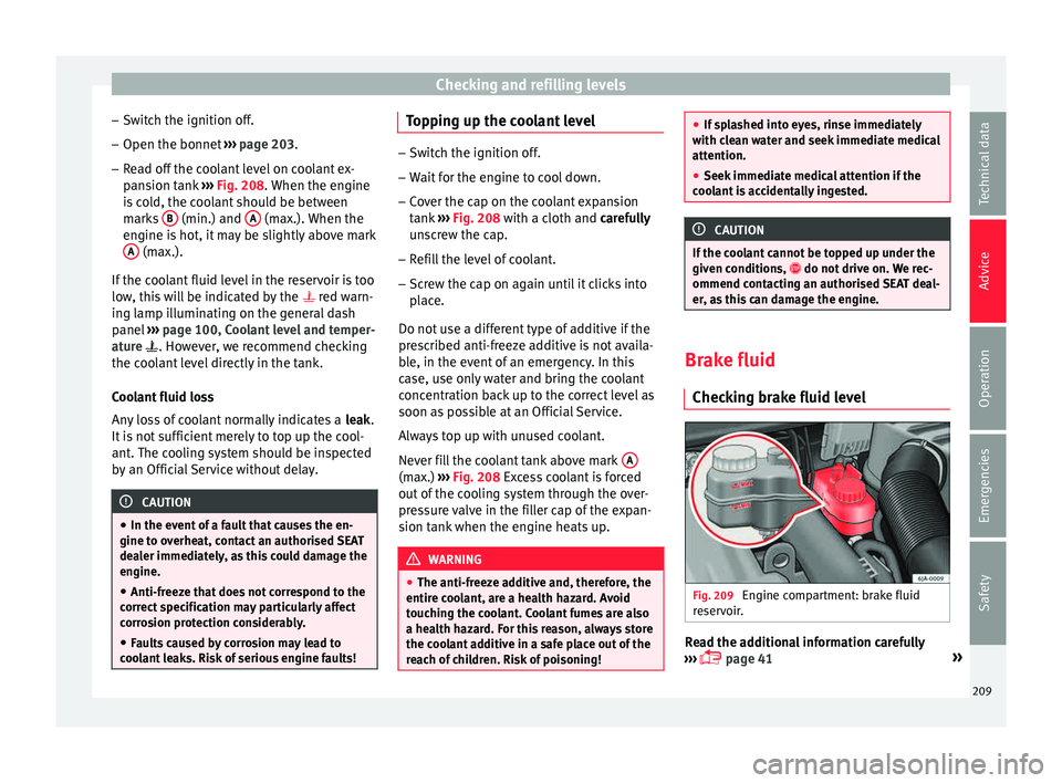
– Read off the coolant level on coolant ex-
pans
ion tank ››› Fig. 208. When the engine
is cold, the coolant should be between
marks B (min.) and
A (max.). When the
en gine i
s
hot, it may be slightly above mark
A (max.).
If the c
oo
lant fluid level in the reservoir is too
low, this will be indicated by the red warn-
ing lamp illuminating on the general dash
panel ››› page 100, Coolant level and temper-
ature . However, we recommend checking
the coolant level directly in the tank.
Coolant fluid loss
Any loss of coolant normally indicates a leak.
It is not sufficient merely to top up the cool-
ant. The cooling system should be inspected
by an Official Service without delay. CAUTION
● In the event of
a fault that causes the en-
gine to overheat, contact an authorised SEAT
dealer immediately, as this could damage the
engine.
● Anti-freeze that does not correspond to the
correct
specification may particularly affect
corrosion protection considerably.
● Faults caused by corrosion may lead to
cool
ant leaks. Risk of serious engine faults! Topping up the coolant level
–
Switch the ignition off.
– Wait for the engine to cool down.
– Cover the cap on the coolant expansion
tank ›
›› Fig. 208 with a cloth and carefully
unscrew the cap.
– Refill the level of coolant.
– Screw the cap on again until it clicks into
plac
e.
Do not use a different type of additive if the
prescribed anti-freeze additive is not availa-
ble, in the event of an emergency. In this
case, use only water and bring the coolant
concentration back up to the correct level as
soon as possible at an Official Service.
Always top up with unused coolant.
Never fill the coolant tank above mark A (max.)
››
›
Fig. 208 Excess coolant is forced
out of the cooling system through the over-
pressure valve in the filler cap of the expan-
sion tank when the engine heats up. WARNING
● The anti-freez e a
dditive and, therefore, the
entire coolant, are a health hazard. Avoid
touching the coolant. Coolant fumes are also
a health hazard. For this reason, always store
the coolant additive in a safe place out of the
reach of children. Risk of poisoning! ●
If s p
lashed into eyes, rinse immediately
with clean water and seek immediate medical
attention.
● Seek immediate medical attention if the
cool
ant is accidentally ingested. CAUTION
If the coolant cannot be topped up under the
giv en c ondition
s, do not drive on. We rec-
ommend contacting an authorised SEAT deal-
er, as this can damage the engine. Brake fluid
Chec kin
g brake fluid level Fig. 209
Engine compartment: brake fluid
r e
ser
voir. Read the additional information carefully
› ›
›
page 41 »
209
Technical data
Advice
Operation
Emergencies
Safety
Page 212 of 248
Advice
The brake fluid reservoir is located in the en-
gine c omp
ar
tment of the vehicle.
– Switch the ignition off.
– Open the bonnet ›››
page 203.
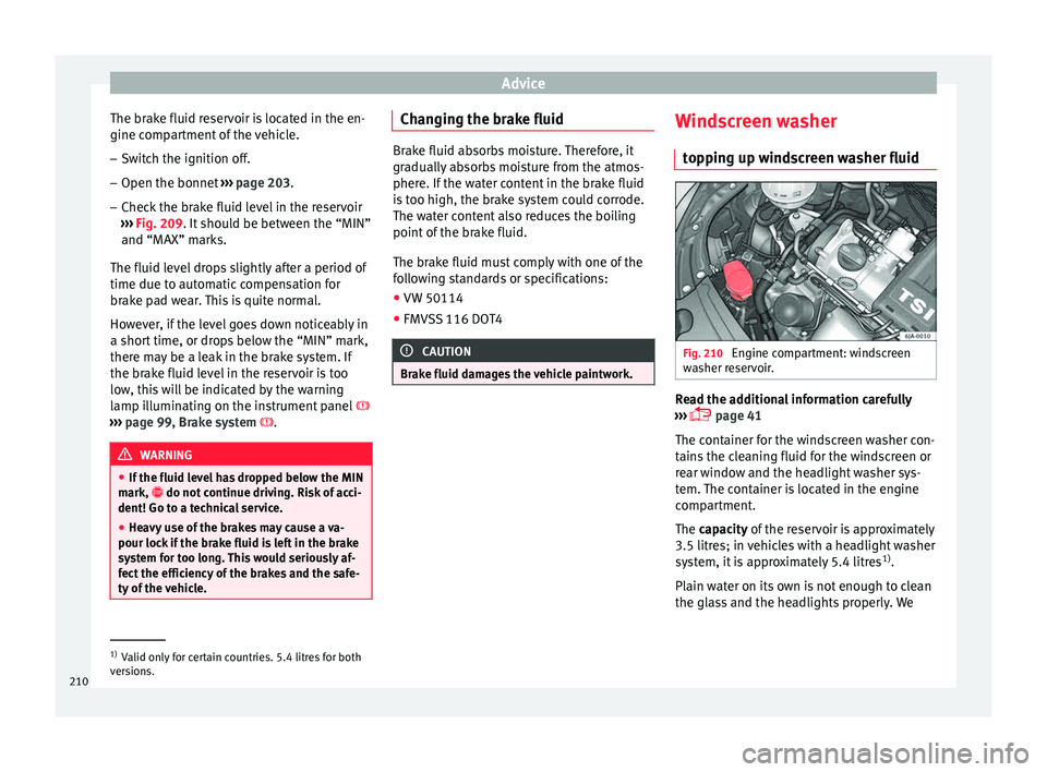
– Check the brake fluid level in the reservoir
›››
Fig. 209. It should be between the “MIN”
and “MAX” marks.
The fluid level drops slightly after a period of
time due to automatic compensation for
brake pad wear. This is quite normal.
However, if the level goes down noticeably in
a short time, or drops below the “MIN” mark,
there may be a leak in the brake system. If
the brake fluid level in the reservoir is too
low, this will be indicated by the warning
lamp illuminating on the instrument panel
››› page 99, Brake system . WARNING
● If the fluid l ev
el has dropped below the MIN
mark, do not continue driving. Risk of acci-
dent! Go to a technical service.
● Heavy use of the brakes may cause a va-
pour lock if
the brake fluid is left in the brake
system for too long. This would seriously af-
fect the efficiency of the brakes and the safe-
ty of the vehicle. Changing the brake fluid
Brake fluid absorbs moisture. Therefore, it
gra
dual
ly absorbs moisture from the atmos-
phere. If the water content in the brake fluid
is too high, the brake system could corrode.
The water content also reduces the boiling
point of the brake fluid.
The brake fluid must comply with one of the
following standards or specifications:
● VW 50114
● FMVSS 116 DOT4 CAUTION
Brake fluid damages the vehicle paintwork. Windscreen washer
top
pin
g up windscreen washer fluid Fig. 210
Engine compartment: windscreen
w a
sher r
eservoir. Read the additional information carefully
› ›
›
page 41
The container for the windscreen washer con-
tains the cleaning fluid for the windscreen or
rear window and the headlight washer sys-
tem. The container is located in the engine
compartment.
The capacity of the reservoir is approximately
3.5 litres; in vehicles with a headlight washer
system, it is approximately 5.4 litres 1)
.
Plain water on its own is not enough to clean
the glass and the headlights properly. We 1)
Valid only for certain countries. 5.4 litres for both
ver s
ions.
210
Page 215 of 248
Checking and refilling levels
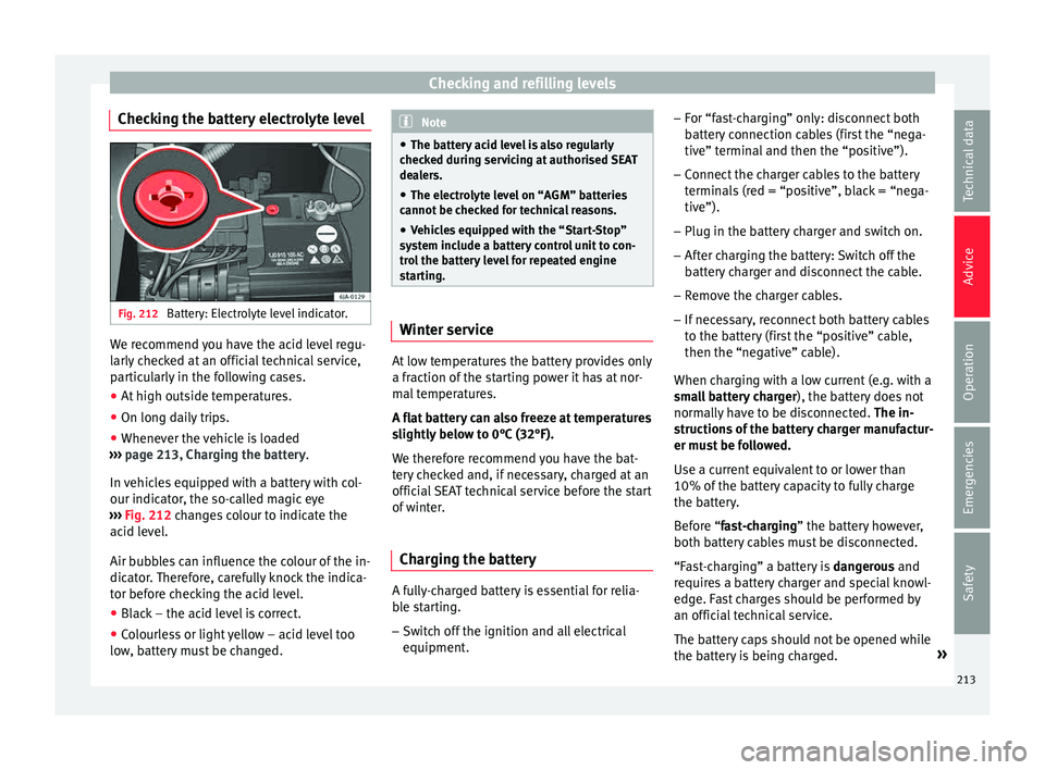
Checking the battery electrolyte level Fig. 212
Battery: Electrolyte level indicator. We recommend you have the acid level regu-
l
arly
c
hecked at an official technical service,
particularly in the following cases.
● At high outside temperatures.
● On long daily trips.
● Whenever the vehicle is loaded
›››
page 213, Charging the battery.
In vehicles equipped with a battery with col-
our indicator, the so-called magic eye
››› Fig. 212 changes colour to indicate the
acid level.
Air bubbles can influence the colour of the in-
dicator. Therefore, carefully knock the indica-
tor before checking the acid level.
● Black – the acid level is correct.
● Colourless or light yellow – acid level too
low , b
attery must be changed. Note
● The batt er
y acid level is also regularly
checked during servicing at authorised SEAT
dealers.
● The electrolyte level on “AGM” batteries
cannot be c
hecked for technical reasons.
● Vehicles equipped with the “Start-Stop”
syst
em include a battery control unit to con-
trol the battery level for repeated engine
starting. Winter service
At low temperatures the battery provides only
a fr
action of
the s
tarting power it has at nor-
mal temperatures.
A flat battery can also freeze at temperatures
slightly below to 0°C (32°F).
We therefore recommend you have the bat-
tery checked and, if necessary, charged at an
official SEAT technical service before the start
of winter.
Charging the battery A fully-charged battery is essential for relia-
b
l
e s
tarting.
– Switch off the ignition and all electrical
equipment. –
For “fa
st-charging” only: disconnect both
battery connection cables (first the “nega-
tive” terminal and then the “positive”).
– Connect the charger cables to the battery
terminal
s (red = “positive”, black = “nega-
tive”).
– Plug in the battery charger and switch on.
– After charging the battery: Switch off the
batter
y charger and disconnect the cable.
– Remove the charger cables.
– If necessary, reconnect both battery cables
to the batt
ery (first the “positive” cable,
then the “negative” cable).
When charging with a low current (e.g. with a
small battery charger ), the battery does not
normally have to be disconnected. The in-
structions of the battery charger manufactur-
er must be followed.
Use a current equivalent to or lower than
10% of the battery capacity to fully charge
the battery.
Before “fast-charging” the battery however,
both battery cables must be disconnected.
“Fast-charging” a battery is dangerous and
requires a battery charger and special knowl-
edge. Fast charges should be performed by
an official technical service.
The battery caps should not be opened while
the battery is being charged. »
213
Technical data
Advice
Operation
Emergencies
Safety
Page 216 of 248
Advice
CAUTION
In vehicles fitted with the “Start-Stop” sys-
tem, the c h
arger cable cannot be directly con-
nected to the negative terminal of the vehicle
battery but must be attached to the engine
ground point ›››
page 52. Disconnecting and connecting the
batt
er
y The following functions will either be inoper-
ative or w
i
ll not work properly after discon-
necting and reconnecting the battery:
FunctionInstallation
Setting the clock››› page 95
The multifunction display data
is deleted››› page 97 Note
We recommend having the vehicle checked by
an authorised S EA
T dealer to guarantee the
correct working order of all electrical sys-
tems. Replacing the battery
A replacement battery must have the same
c
ap
ac
ity, voltage, current rating and size as
the original. The appropriate types of battery can be acquired from authorised SEAT deal-
ers.
We r
ecommend having the battery changed
by an authorised SEAT dealer, where the new
battery will be correctly installed and the
original disposed of in line with regulations.
Automatic disconnection of electrical
equipment When heavily-charging a battery, the pro-
gr
amme sel
ect
ed by the electrical system
control unit prevents the battery from auto-
matically discharging. This may result in the
following:
● Increase in idling speed so that the alterna-
tor can s
upply more current to the electrical
system.
● The performance of certain electrical com-
ponents cou
ld be limited or some may switch
off temporarily, e.g. the heated seats, the
heated rear window, the 12 V power socket. Note
Despite any measures taken by the control
unit, the b att
ery could drain. e.g. with the en-
gine is switched off, the key is turned in the
ignition for a long period or the side lights or
parking lights are switched on. The switching
off of certain electrical components does not impair driving comfort and often the driver
wi
l
l not even notice.214