navigation system Seat Toledo 2015 Owner's manual
[x] Cancel search | Manufacturer: SEAT, Model Year: 2015, Model line: Toledo, Model: Seat Toledo 2015Pages: 248, PDF Size: 5.06 MB
Page 25 of 248
The essentials
Navigation ›››
Book
l et Navigation system
Audio ››› Booklet Radio or ››› Booklet Naviga-
tion system
Telephone ››› Booklet Radio or ››› Book-
let Navigation system
Vehicle ››› table on page 24 WARNING
Any distraction may lead to an accident, with
the risk of
injury.
● Do not operate the instrument panel con-
trol
s when driving. Operating the instrument panel me-
nu
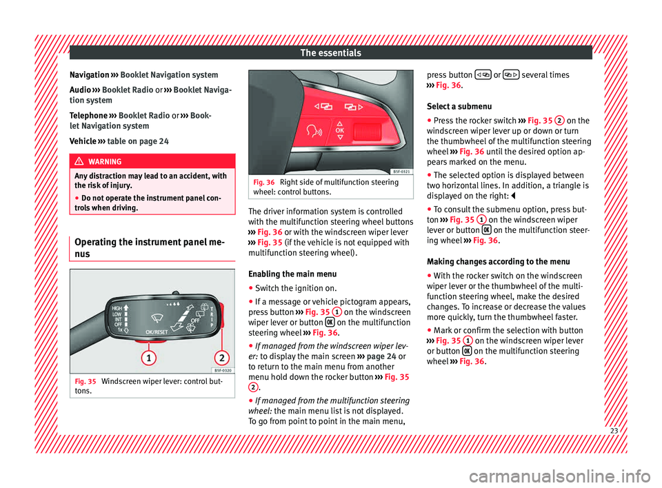
s Fig. 35
Windscreen wiper lever: control but-
t on
s. Fig. 36
Right side of multifunction steering
wheel: contr o
l buttons. The driver information system is controlled
w
ith the mu
ltif
unction steering wheel buttons
››› Fig. 36 or with the windscreen wiper lever
››› Fig. 35 (if the vehicle is not equipped with
multifunction steering wheel).
Enabling the main menu
● Switch the ignition on.
● If a message or vehicle pictogram appears,
pres
s button ››› Fig. 35 1 on the windscreen
w iper l
ev
er or button on the multifunction
s t
eerin
g wheel ››› Fig. 36.
● If managed from the windscreen wiper lev-
er: to dis
play the main screen ››› page 24 or
to return to the main menu from another
menu hold down the rocker button ››› Fig. 35
2 .
● If managed from the multifunction steering
whee l:
the main menu list is not displayed.
To go from point to point in the main menu, press button
or
several times
› ›
›
Fig. 36.
Select a submenu ● Press the rocker switch ›››
Fig. 35 2 on the
w ind
s
creen wiper lever up or down or turn
the thumbwheel of the multifunction steering
wheel ››› Fig. 36 until the desired option ap-
pears marked on the menu.
● The selected option is displayed between
two horizont
al lines. In addition, a triangle is
displayed on the right:
● To consult the submenu option, press but-
ton ››
› Fig. 35 1 on the windscreen wiper
l ev
er or b
utton on the multifunction steer-
in g wheel
›
›› Fig. 36.
Making changes according to the menu ● With the rocker switch on the windscreen
wiper lev
er or the thumbwheel of the multi-
function steering wheel, make the desired
changes. To increase or decrease the values
more quickly, turn the thumbwheel faster.
● Mark or confirm the selection with button
›››
Fig. 35 1 on the windscreen wiper lever
or b utt
on on the multifunction steering
wheel
›
›
› Fig. 36. 23
Page 26 of 248
The essentials
MenuMenuFunction
Driving dataInformation and possible configurations
of the multifunction display (MFD)
››› page 26, ››› page 104.
Assist
systemsInformation and possible configurations
of the driver assistance systems
››› page 104.
Naviga-
tion
Information instructions from the activa-
ted navigation system: when a route guid-
ance is activated, the turning arrows and
proximity bars are displayed. The appear-
ance is similar to the Easy Connect sys-
tem.
If route guidance is not activated, the di-
rection of travel (compass) and the name
of the street along which you are driving
are shown ››› Booklet Navigation system.
Audio
Station display on the radio.
Track name on the CD.
Track name in Media mode ››› Booklet Ra-
dio or ››› Booklet Navigation system.
Tele-
phoneInformation and possible configurations
of the mobile phone preinstallation
››› Booklet Radio or ››› Booklet Navigation
system.
Lap tim-
er *In a racing circuit, measurement and
memorisation of lap times by the vehicle
and comparison with previously measured
best times ››› page 28.
MenuFunction
Vehicle
statusDisplay of the current warning or informa-
tion texts and other system components,
depending on the equipment
››› page 104. Outside temperature display
When the outside temperature is below +4°C
(+39°F), the symbol
“ice crystal” (warning of
risk of freezing) is also displayed. At first, this
symbol flashes and then it remains lit until
the outside temperature rises above +6°C
(+43°F) ››› in Indications on the display on
p ag
e 96
.
When the vehicle is at a standstill or when
travelling at very low speeds, the tempera-
ture displayed may be higher than the true
outside temperature as a result of the heat
produced by the engine.
The temperatures measured range from
-40°C to +50°C (-40°F to +122°F). Gear-change indicator
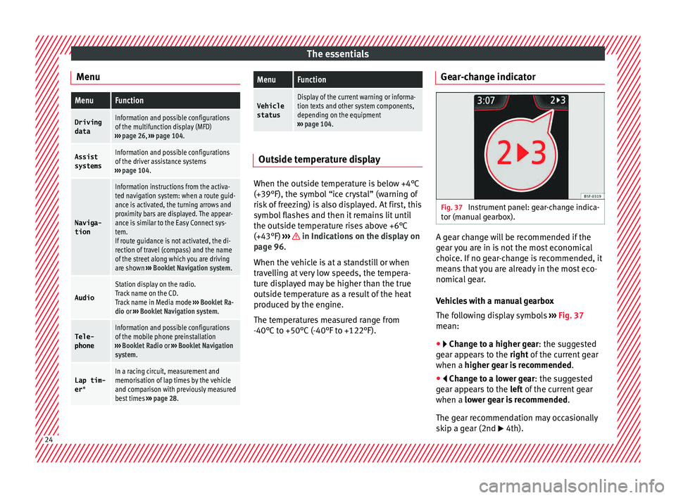
Fig. 37
Instrument panel: gear-change indica-
t or (m
anual
gearbox). A gear change will be recommended if the
g
e
ar
you are in is not the most economical
choice. If no gear-change is recommended, it
means that you are already in the most eco-
nomical gear.
Vehicles with a manual gearbox
The following display symbols ››› Fig. 37
mean:
● Chan ge to a higher gear: the suggested
g
ear appears to the right of the current gear
when a higher gear is recommended .
● Change to a lower gear: the suggested
g
ear appears to the left of the current gear
when a lower gear is recommended .
The gear recommendation may occasionally
skip a gear (2nd 4th). 24
Page 83 of 248
Fuses and bulbs
●
Prot ect
the fuse boxes when open to pre-
vent the entry of dust or humidity as they can
damage the electrical system.
● Always carefully remove the fuse box cov-
ers and r
efit them correctly to avoid problems
with your vehicle. Note
● One c omponent m
ay have more than one
fuse.
● Several components may run on a single
fuse.
● In the
vehicle, there are more fuses than
those indicat
ed in this chapter. These should
only be changed by a specialised workshop.
● Positions not containing a fuse do not ap-
pear in the fo
llowing tables.
● Some of the equipment listed in the tables
below pert
ain only to certain versions of the
model or are optional extras.
● Please note that the above lists, while cor-
rect at
the time of printing, are subject to
change. Fuses in the dash panel
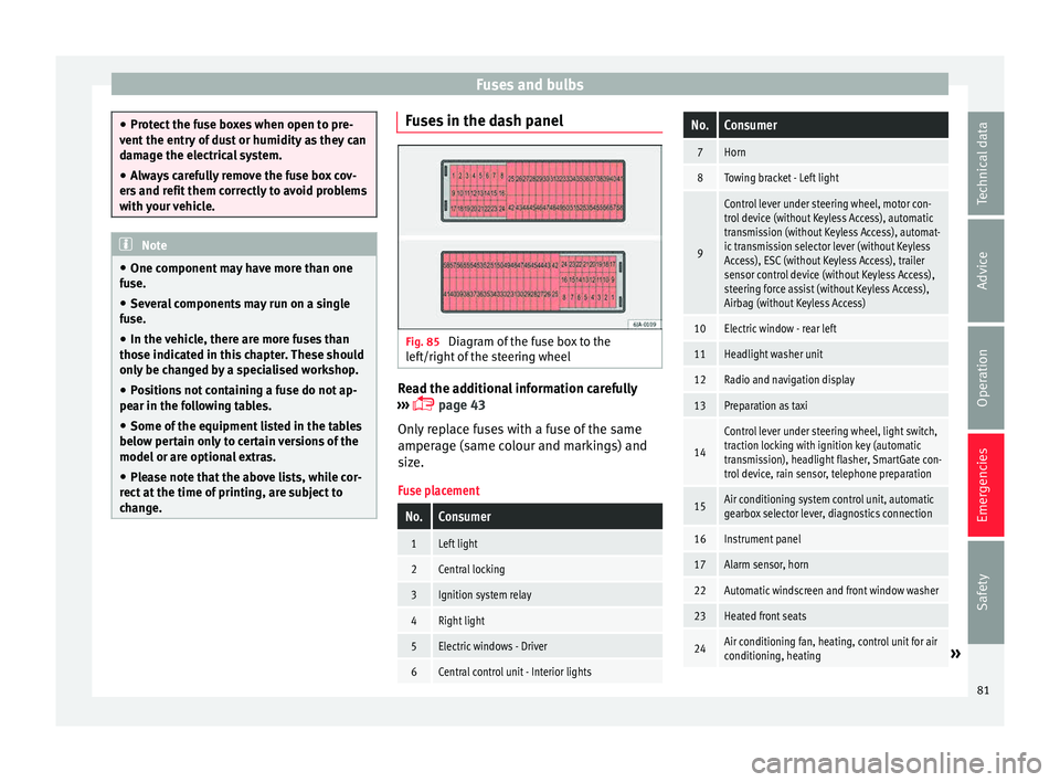
Fig. 85
Diagram of the fuse box to the
l ef
t/right
of the steering wheel Read the additional information carefully
› ›
›
page 43
Only replace fuses with a fuse of the same
amperage (same colour and markings) and
size.
Fuse placement
No.Consumer
1Left light
2Central locking
3Ignition system relay
4Right light
5Electric windows - Driver
6Central control unit - Interior lights
No.Consumer
7Horn
8Towing bracket - Left light
9
Control lever under steering wheel, motor con-
trol device (without Keyless Access), automatic
transmission (without Keyless Access), automat-
ic transmission selector lever (without Keyless
Access), ESC (without Keyless Access), trailer
sensor control device (without Keyless Access),
steering force assist (without Keyless Access),
Airbag (without Keyless Access)
10Electric window - rear left
11Headlight washer unit
12Radio and navigation display
13Preparation as taxi
14
Control lever under steering wheel, light switch,
traction locking with ignition key (automatic
transmission), headlight flasher, SmartGate con-
trol device, rain sensor, telephone preparation
15Air conditioning system control unit, automatic
gearbox selector lever, diagnostics connection
16Instrument panel
17Alarm sensor, horn
22Automatic windscreen and front window washer
23Heated front seats
24Air conditioning fan, heating, control unit for air
conditioning, heating» 81
Technical data
Advice
Operation
Emergencies
Safety
Page 97 of 248
Instruments and warning lamps
CAUTION
● To pr ev
ent damage to the engine, the rev
counter needle should only remain in the red
zone for a short period of time.
● When the engine is cold, avoid high revs
and heavy ac
celeration and do not make the
engine work hard. For the sake of the environment
Changing up a gear in time reduces fuel con-
sumption and noi se.Rev counter
The rev counter indicates the number of en-
gine r
ev
o
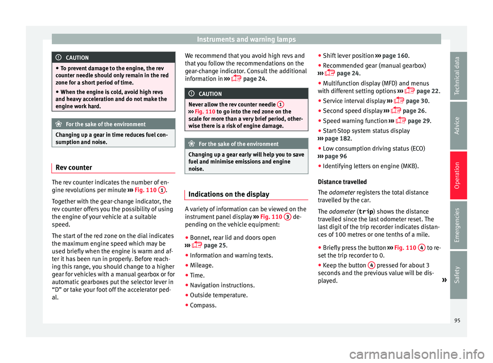
lutions per minute ›››
Fig. 110 1 .
T og
ether w
ith the gear-change indicator, the
rev counter offers you the possibility of using
the engine of your vehicle at a suitable
speed.
The start of the red zone on the dial indicates
the maximum engine speed which may be
used briefly when the engine is warm and af-
ter it has been run in properly. Before reach-
ing this range, you should change to a higher
gear for vehicles with a manual gearbox or for
automatic gearboxes put the selector lever in
“D” or take your foot off the accelerator ped-
al. We recommend that you avoid high revs and
that
you follow the recommendations on the
gear-change indicator. Consult the additional
information in ›››
page 24. CAUTION
Never allow the rev counter needle 1 ›››
Fig. 110 to g o int
o the red zone on the
scale for more than a very brief period, other-
wise there is a risk of engine damage. For the sake of the environment
Changing up a gear early will help you to save
fuel and minimi
se emissions and engine
noise. Indications on the display
A variety of information can be viewed on the
in
s
trument
panel display ›››
Fig. 110 3 de-
pendin g on the
v
ehicle equipment:
● Bonnet, rear lid and doors open
›››
page 25.
● Information and warning texts.
● Mileage.
● Time.
● Navigation instructions.
● Outside temperature.
● Compass. ●
Shift l
ever position ››› page 160.
● Recommended gear (manual gearbox)
›››
page 24.
● Multifunction display (MFD) and menus
with differ
ent setting options ›››
page 22.
● Service interval display ›››
page 30.
● Second speed display ›››
page 26.
● Speed warning function ›››
page 29.
● Start-Stop system status display
›››
page 182.
● Low consumption driving status (ECO)
›››
page 96
● Identifying letters on engine (MKB).
Dist
ance travelled
The odometer registers the total distance
travelled by the car.
The odometer (trip ) shows the distance
travelled since the last odometer reset. The
last digit of the trip recorder indicates distan-
ces of 100 metres or one tenths of a mile.
● Briefly press the button ›››
Fig. 110 4 to re-
set the trip r
ec
order to 0.
● Keep the button 4 pressed for about 3
sec ond
s
and the previous value will be dis-
played. »
95
Technical data
Advice
Operation
Emergencies
Safety
Page 98 of 248
Operation
Time
● To set the time, keep the button ››
› Fig. 110
4 pressed for more than 3 seconds to select
the hour or minut e di
s
play.
● To continue setting the time, press the up-
per or lower p
art of the button 4 . Hold but-
t on do
wn t
o scroll through the numbers
quickly.
● Press the button 4 again in order to finish
settin g the time.
The time c an al
so be set via the key and
Set up function button in the Easy Connect
sy s
t
em ››› page 104.
Compass
With the ignition on and the navigation sys-
tem on, the cardinal point corresponding to
the direction of travel of the vehicle is dis-
played on the instrument panel.
Selector lever position
The selected gear is displayed on the side of
the selector lever and on the instrument pan-
el display. In positions D and S, and with the
Tiptronic, the corresponding gear is also dis-
played.
Recommended gear (manual gearbox)
The recommended gear in order to save fuel
is displayed on the instrument panel while
you are driving ›››
page 24. Second speed display (mph or km/h)
In addition t
o the speedometer, the speed
can also be displayed in a different unit of
measurement (in miles or in km per hour).
This option cannot be deactivated in models
destined for countries in which the second
speed must always be visible.
The second speed display can be adjusted in
the Easy Connect system via the key and
the Set
up function button
››
›
page 104.
Speed warning
When the speed setting is exceeded, this will
be indicated on the instrument panel display.
This is very useful, for example when using
winter tyres that are not designed for driving
at the maximum speed of the vehicle
››› page 29.
The speed warning settings can be adjusted
in the Easy Connect system via the key
and the Set
up function button
››
›
page 104.
Start-Stop operating display
Updated information relating to the status is
displayed on the instrument panel
››› page 182.
Low consumption driving status (ECO)*
Depending on the equipment, when driving,
the “ECO ” display appears on the instrument panel when the vehicle is in low consump-
tion stat
us.
Identifying letters on engine (MKB)
Hold the button ››› Fig. 110 4 down for more
th an 15 sec
ond
s to display the identifying
letters of the vehicle engine (MKB). To do
this, the ignition must be switched on and
the engine switched off. WARNING
Observe the safety warnings ›››
in Warning
and indication l amp
s on page 98. WARNING
Even though outside temperatures are above
freez in
g, some roads and bridges may be icy.
● At outside temperatures above +4°C
(+39°F), even when the “ice c
rystal symbol”
is not visible, there may still be patches of ice
on the road.
● Never rely on the outside temperature indi-
cator! Note
● Differ ent
versions of the instrument panel
are available and therefore the versions and
instructions on the display may vary. In the
case of displays without warning or informa-
tion texts, faults are indicated exclusively by
the warning lamps. 96
Page 107 of 248
Communications and multimedia
Communications and multi-
medi a
St eerin
g wheel controls*
General information The vehicle includes a multifunction module
from wher
e it
is possible to control the audio,
telephone and radio/navigation functions
without needing to distract the driver.
There are two versions of the multifunction
module:
● Audio version, to control the available au-
dio fu nction
s from the steering wheel (Radio,
audio CD, MP3 CD, iPod ®1)
, USB 1)
).
● Audio + telephone versions o control the
avail
able audio functions from the steering
wheel (Radio, audio CD, MP3 CD, iPod ®1)
,
USB 1)
, SD 1)
) and the Bluetooth system. 1)
Depending on the vehicle equipment.
105
Technical data
Advice
Operation
Emergencies
Safety
Page 109 of 248
Communications and multimedia
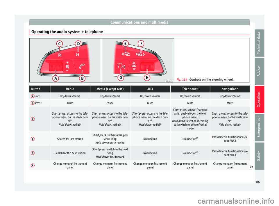
Operating the audio system + telephone Fig. 114
Controls on the steering wheel.ButtonRadioMedia (except AUX)AUXTelephone a)Navigation a)
A TurnUp/down volumeUp/down volumeUp/down volumeUp/down volumeUp/down volume
A PressMutePauseMuteMuteMute
B
Short press:
access to the tele-
phone menu on the dash pan- ela)
.
Hold down: redial a)Short press:
access to the tele-
phone menu on the dash pan- ela)
.
Hold down: redial a)Short press:
access to the tele-
phone menu on the dash pan- ela)
.
Hold down: redial a)Short press:
answer/hang up
calls, enable/open the tele- phone menu.
Hold down: reject an incoming call/switch to private/redial modeShort press: access to the tele-
phone menu on the dash pan- ela)
.
Hold down: redial a)
CSearch for last stationShort press:
switch to the pre-
vious song
Hold down: quick rewindNo functionNo function b)Radio/media functionality (ex-
cept AUX )
DSearch for the next stationShort press: switch to the next
song
Hold down: fast forwardNo functionNo function b)Radio/media functionality (ex-
cept AUX )
EChange menu on instrument panelChange menu on instrumentpanelChange menu on instrumentpanelChange menu on instrumentpanelChange menu on instrumentpanel» 107
Technical data
Advice
Operation
Emergencies
Safety
Page 111 of 248
Opening and closing
Multimedia USB/A UX
-IN inp
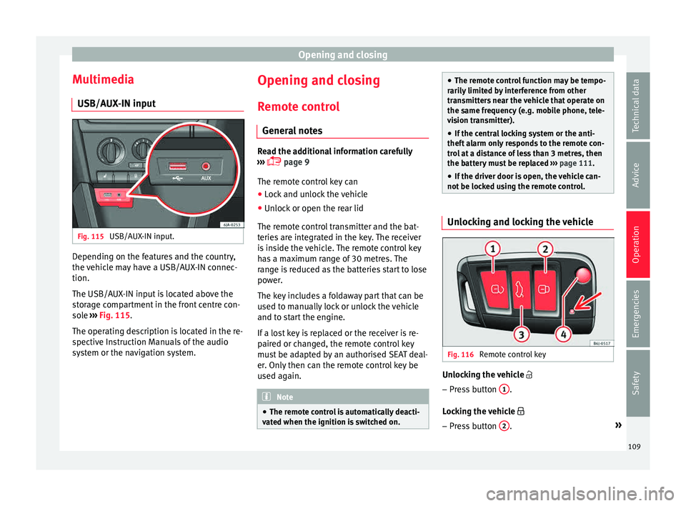
utFig. 115
USB/AUX-IN input. Depending on the features and the country,
the
v
ehic
le may have a USB/AUX-IN connec-
tion.
The USB/AUX-IN input is located above the
storage compartment in the front centre con-
sole ››› Fig. 115.
The operating description is located in the re-
spective Instruction Manuals of the audio
system or the navigation system. Opening and closing
R emot
e c
ontrol
General notes Read the additional information carefully
›› ›
page 9
The remote control key can
● Lock and unlock the vehicle
● Unlock or open the rear lid
The remot e c
ontrol transmitter and the bat-
teries are integrated in the key. The receiver
is inside the vehicle. The remote control key
has a maximum range of 30 metres. The
range is reduced as the batteries start to lose
power.
The key includes a foldaway part that can be
used to manually lock or unlock the vehicle
and to start the engine.
If a lost key is replaced or the receiver is re-
paired or changed, the remote control key
must be adapted by an authorised SEAT deal-
er. Only then can the remote control key be
used again. Note
● The remot e c
ontrol is automatically deacti-
vated when the ignition is switched on. ●
The remot e c
ontrol function may be tempo-
rarily limited by interference from other
transmitters near the vehicle that operate on
the same frequency (e.g. mobile phone, tele-
vision transmitter).
● If the central locking system or the anti-
theft a
larm only responds to the remote con-
trol at a distance of less than 3 metres, then
the battery must be replaced ››› page 111.
● If the driver door is open, the vehicle can-
not be lock
ed using the remote control. Unlocking and locking the vehicle
Fig. 116
Remote control key Unlocking the vehicle
– Press button 1 .
L oc
k
ing the vehicle
– Press button 2 .
»
109
Technical data
Advice
Operation
Emergencies
Safety
Page 175 of 248
Driver assistance systems
Error messages When the Parking Aid is activated or when it
is
sw
itched on, if a continuous warning can
be heard for several seconds (additionally, in
the case of Parking system Plus, the LED of
the button flashes), there is a fault in the
system.
Parking System Plus*
If there is a fault in a sensor, the symbol is
displayed on the Easy Connect display in
front of/behind the vehicle. If a rear sensor is
faulty, only the obstacles in the areas A and
B are displayed
››
›
Fig. 181. If a front sensor
is faulty, only the obstacles in the areas Cand
D are displayed.
Hav e the f
au
lt corrected by a specialised
workshop without delay.
Towing bracket In vehicles equipped with a towing bracket
dev
ic
e fr
om the factory, when the trailer is
connected electrically, the Parking Aid rear
sensors will not be activated when reverse
gear is engaged, when the selector lever is
turned to position R or when the button is
pressed. Parking System Plus
The dist
ance to possible obstacles at the rear
of the vehicle will not be displayed on the
screen and nor will it be indicated by means
of audible sound signals.
The Easy Connect system screen will only dis-
play objects detected at the front, and the ve-
hicle's trajectory will be hidden.
Rear Assist “Rear View Cam-
era”*
Operatin
g and safety warnings WARNING
● The Re ar As
sist does not make it possible
to precisely calculate the distance from ob-
stacles (people, vehicles, etc.) and nor can it
overcome the system's own limits, hence us-
ing it may cause serious accidents and inju-
ries if used negligently or without due care.
The driver should be aware of his/her sur-
roundings at all times to ensure safe driving.
● The camera lens expands and distorts the
field of
vision and displays the objects on the
screen in a different, vague manner. The per-
ception of distances is also distorted by this
effect.
● Some objects may, due to the resolution of
the disp
lay screen - not be displayed in a sat-
isfactory manner or may not be displayed at all. Take special care with thin posts, fences,
rai
lin
gs or trees that might not be displayed
on screen and could damage the vehicle.
● The rear assist has blind spots where it is
not pos
sible to represent people or objects
(small children, animals and certain objects
cannot be detected in its field of vision). Mon-
itor the vehicle's surrounding area at all
times.
● Keep the camera lens clean, free of ice and
snow
, and do not cover it.
● The system is not a replacement for driver
awar
eness. Supervise the parking operation
at all times, as well as the vehicle's surround-
ing area. Adapt your speed and driving style
at all times to suit visibility, weather, road
and traffic conditions.
● Do not be distracted from the traffic by
looking at
the screen.
● The images on the rear assist screen are
only tw
o-dimensional. Due to a lack of spatial
depth, protruding parts or holes in the road,
for example, are more difficult to detect or
may not be seen at all.
● Vehicle load modifies the representation of
the orientation lines
displayed. The width
represented by the lines diminishes with ve-
hicle load. Pay special attention to the vehi-
cle's surroundings when the inside of the ve-
hicle of the luggage compartment is carrying
a heavy load.
● In the following situations, the objects or
other vehic
les shown in the navigation sys-
tem display appear to be further away or » 173
Technical data
Advice
Operation
Emergencies
Safety
Page 196 of 248
Advice
●
The modification of the s
uspension of the
vehicle wheels, including the use of non-per-
mitted combinations of tyres and rims can al-
ter the operation of the airbag system and in-
crease the risk of serious or fatal injuries in
an accident.
● During all jobs on the airbag system, in ad-
dition to the remo
val and fitting of parts of
the system in the course of other repair jobs,
parts of the airbag system can be damaged.
Therefore in the event of an accident, this
may cause the airbags to activate incorrectly
or not activate at all. Radio and aerial reception
In vehicles factory-fitted with an audio or
n
av
ig
ation system, the aerial may be instal-
led in different places:
● inside the rear window next to the heating
elements,
● on the roof
of the vehicle.
Care and cleaning Introduction Regular and suitable care helps to
m
aint ain
the u
seful life of your vehicle. This may also
be one of the requirements for upholding any warranty claims in the event of corrosion or
paint def
ects.
We recommend you use cleaning products
from the SEAT Original Accessories pro-
gramme available in SEAT dealers. Please fol-
low the instructions for use on the packag-
ing. WARNING
● Cle
aning products and other materials used
for car care can damage the health if mis-
used.
● Always keep car care materials in a safe
plac
e out of the reach of children. Risk of poi-
soning!
● When washing the car during the winter
season: Moi
sture and ice on the brakes may
affect braking efficiency. Risk of accident!
● The ignition must always be switched off
when the car is
washed. Risk of accident!
● Do not clean the underside of the car or in-
side the wheel ar
ches without protecting your
hands and arms. You may cut yourself on
sharp metal parts!
● Perfumes and air fresheners inside the ve-
hicle m
ay be harmful to health at high tem-
peratures in the interior. CAUTION
● Check the c
olour-fastness of your clothing
to avoid damaging or visibly staining the fab-
ric (leather), upholstery and fabric trim. ●
Cle
aning products containing solvents may
damage the material being cleaned.
● Do not wash the vehicle in direct sunlight.
Risk of
damage to paintwork.
● If washing the vehicle with a hose in win-
ter, do not
direct the jet of water directly at
the locks or at the door seals or bonnet. Risk
of freezing.
● Do not use sponges for removing insects or
abras
ive household sponges, etc. on painted
surfaces. Risk of damage to the painted sur-
face!
● Do not put stickers on the inner side of the
rear w
indow in areas where heating elements
or the aerial are located. This could cause
damage and, in the case of the aerial, radio
and navigation system reception faults.
● Do not clean the inside of the window with
sharp ob
jects or corrosive or acidic cleaning
products. Risk of damaging the heating ele-
ments or the aerial.
● Do not attach any fragrance or air freshener
to the da
sh panel. Risk of damage to the
dash panel!
● To avoid damaging the parking aid system
sensors, s
pray them only briefly at a mini-
mum distance of 10 cm when cleaning the ve-
hicle with a high-pressure or steam cleaner.
● Do not clean the roof panel with a brush.
Risk of
damage to the panel surface!194