dimensions SKODA 120 LS 1980 Workshop Manual
[x] Cancel search | Manufacturer: SKODA, Model Year: 1980, Model line: 120 LS, Model: SKODA 120 LS 1980Pages: 238, PDF Size: 47.09 MB
Page 22 of 238
il
tli
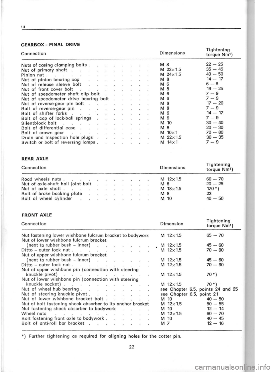
GEARBOX. FINAL
DRIVE
Connection DimensionsTightening
torque Nmt)
Nuts of cosing clomping bolts .
Nut of primory shoft
Plnlon nut .
Nut of pinion
beoring coP
Nut of releose sleeve
bol
Nut of front cover bolt
Nut of speedometer shoft clip bolt
Nut of speedometer drive beoring
bolt
Nut of reverse-geor pin
bolt
Bolt of reverse-geor pin
Bolt of shifter forks
Bolt of cop of lock-boll springs
Silentblock bolt
Bolt of differentiol cose
Bolt of crown geor
Droin ond inspection hole plugs
Switch or bolt of reversing lomps .
REAR AXLE
Connection M8
M 22x1.5
M 24x1.5
M8
M6 M8
M 22x1.5
M 14x1
Dimensions 40-50
14-17
6-8 19-25
7-9
7-9 17 -20
7 -9
14-17
7 -9
30-40 22-25
35-45
20-30
70-80
M6
M6
M8
M8
M6
M6
M10
M8
M 10x1 30-35
7 -9
Tightening torque Nmr)
Rood wheels nuts .
Nut of oxle-shoft boll
Nut of oxle shoft
.ioin;
boit M 12x1.5
M8 M 18x1.5
M8
M10
Dimension 60-70
20-25
17O *)
a
40-50
Bolt of broke
bocking plote
Bolt of wheel cylinder
FRONT AXIE
Connection Tightening
torque Nml)
Nut fostening lower wishbone fulcrum
brocket to bodywork
Nut of lower wishbone fulcrum
brocket
(next to rubber bush -
inner)
Ditto -
outer lock nut .
Nut of upper wishbone fulcrum
brocket
(next to rubber bush -
inner)
Ditto -
outer lock nut .
Nut of upper wishbone pin (connection
with steering
knuckle pivot)
Nut of lower wishbone pin (connection
with steering
knuckle socket)
Nut of wheel
hub beoring .
Nut of steering knuckle pivot
.
Nut of lower
wishbone brocket bolt .
Nut of bolt fostening shock obsorber to its onchor brocket
Nut fostening shock
obsorber to
bodywork
Wheel nuts
Bolt fostening
front oxle to bodywork .
Bolt of
onti-roll bor brocket see
Chopter 6.5, points
24 ond 25
see Chopter 6.5, point
21
M
,M M
M
M
M 12x1.5
12x1.5
12x1.5
12x1.5
12x1.5
12x1.5 6s-70
45-60
70-90
45-60
70-90
70*)
70 *l
40-50 50-55 12-14
60-70
40-45
12-16
M
12x1.5
M10
M 12x1.5
M10
M 12x1.5
M10
M7
*) Further tightening os
required for olignlng holes
for the cotter pin.
22
Page 32 of 238
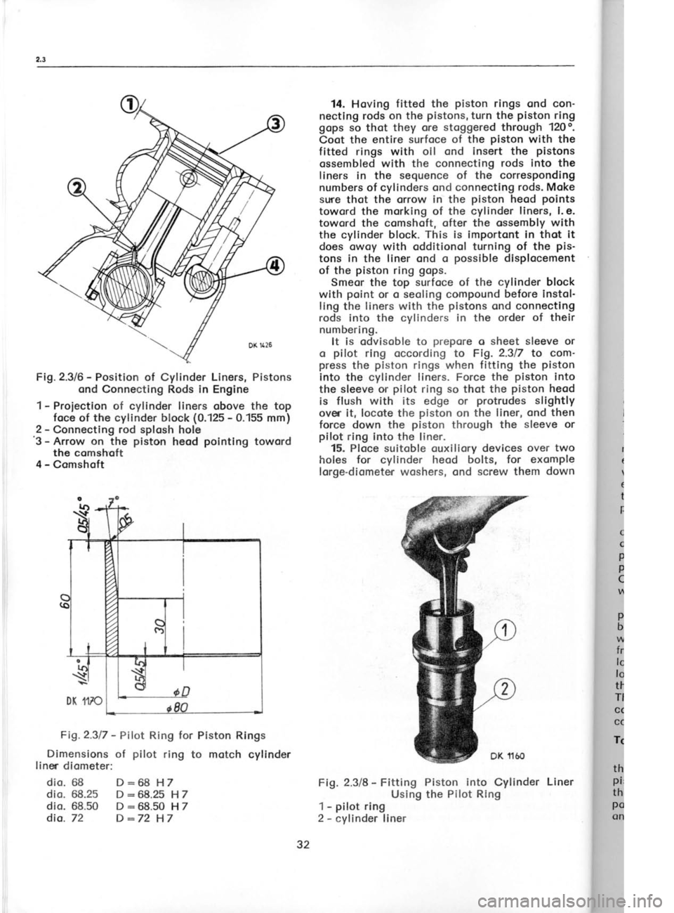
Fig.2.3/6
-
Position of Cylinder Liners,
Pistons
ond Connecting Rods in Engine
1 -
Proiectlon of cylinder liners
obove the top
foce of the cylinder block (0.125 -
0.155 mm)
2 -
Connecting rod splosh hole
'3
- Arrow on the piston
heod pointlng
toword
the comshoft
4 -
Comshoft
Fig.2.317 -
Pilot Ring
for Piston Rings
Dimensions of pilot
ring to motch cylinder
liner diometer:
dio. 68 D:68 H 7
dio. 68.25 D :68.25
H 7
dio. 68.50 D :68.50
H 7
dia. 72 D:72 H7 14.
Hoving fitted the piston
rings ond con-
nectlng rods on the pistons,
turn the piston
ring
gops so thot they ore stoggered
through 120o.
Coot the entire surfoce of the piston
with the
fitted rings with oll ond insert the pistons
ossembled with the connecting rods into the
liners in the sequence of the corresponding
numbers of cylinders ond connecting rods. Moke
sure thot the
orrow in the piston
heod points
toword the morking
of the cylinder liners, l.e.
toward the comshoft, ofter the ossembly with
the cylinder block. This
is importont in thot it
does owoy with odditionol turning of the pis-
tons in the liner ond o posslble
displocement
of the piston
ring gops.
Smeor the top surfoce of the cylinder block
with point
or o seoling
compound before
instol-
ling the liners with the pistons
ond connectlng
rods into the cylinders in the order of their
numbering. It is odvisoble to prepore
o sheet sleeve or
o pilot
ring occording to Fig. 2.317
to com-
press the piston
rings when fitting
the piston
Into the cylinder liners. Force the piston
into
the sleeve or pilot
ring so
thot the piston
heod
is flush with its edge or protrudes
sllghtly
over it, locote the piston
on the liner, ond then
force down the piston
through the sleeve or
pilot ring into the liner.
15. Ploce suitoble ouxiliory devices over two
holes for
cylinder heod bolts, for exomple
lorge-diometer woshers, ond screw them down
Fig. 2.3/8 -
Fitting Piston into
Cylinder Liner
Using the Pilot Rlng
1 -
pilot ring
2 -
cylinder liner
32
Page 40 of 238
For the
instol lotion of the engine on the test
bench, we indicote the dimensions
of the en'
gine flonge ond flywheel. During broking, the
engine qnd
the engine oil must
be properly
cooled to preclude
exceeding the oPtimum
service conditions, i. e. woter temperoture
ofobout
80 to 90oC, ond oil temperoture of 12O"C
moximum -
see Chopter 2.5,
porogroph 51.
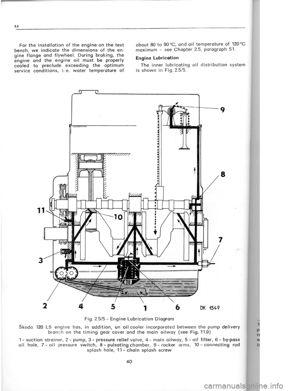
Engine Lubricotion
The inner lubricoting oil distribution system
is shown in Fig.2.5/5.
6 DK .r5+9 2.6
cYL
The cyl
mochined
the cronl
ports, forr
ore mode
B locks fo
72 mm di
I i ners.
Oilwoys, I
o) Befo
o new cyl
ossembled
blow thror"
b) Coot
pound or p
the oilwoy
c) Likev
into the e
pound or p,
of the
cyli
one (of
lo
limits indi
Ports) to er
d) Tighte
ot cylinder
under it.
e) Foster
the cop of
Fosten the
with o bolt
Fig.2.611 ond
1 -
choin gre
plug, 3 -
iniel
relief volve,
with cop, 6 -
inlet from o
ptug, I
9
8
7
5t
Fig.2.515 -
Engine Lubricotion Diognom
Skodo 120 LS
engine hos,
in oddition, on oil cooler incorporoted between the punrp
delivery
broncir on the timing geor
cover ond the moin oilwoy (see
Fi9.11.9)
srlctionstroiner,2-pump,3-pressurereliefvolve,4-moinoilwoy,5-oil filter,6-by-poss
hole, 7- oil pressure
switch, 8-pulsotingchomber, 9- rocker orms, 10-connecting rod
splosh hole, 11 -
choin splosh screw
4
2
4 t-
oil I
?
?
I
;
t
Page 42 of 238
2.6-2.7
seot in the cylinder block using o copper or
oluminium rod.
Reconditioning Recesses for
Cylinder Liner
Flonges
Before ossembling o used
cylinder block,
inspect ond cleorr thoroughly the moting
sur-
foces of the recesses for
cylinder liner f
longes.
lf chemicol ogents (petrol,
etc.) foil
to hove
the required
effect, or if the surfoces hove
been domoged
mechonicolly, use the MP 1-106
dresser, or the MP 1-157
iig with
universol guicc
rings.
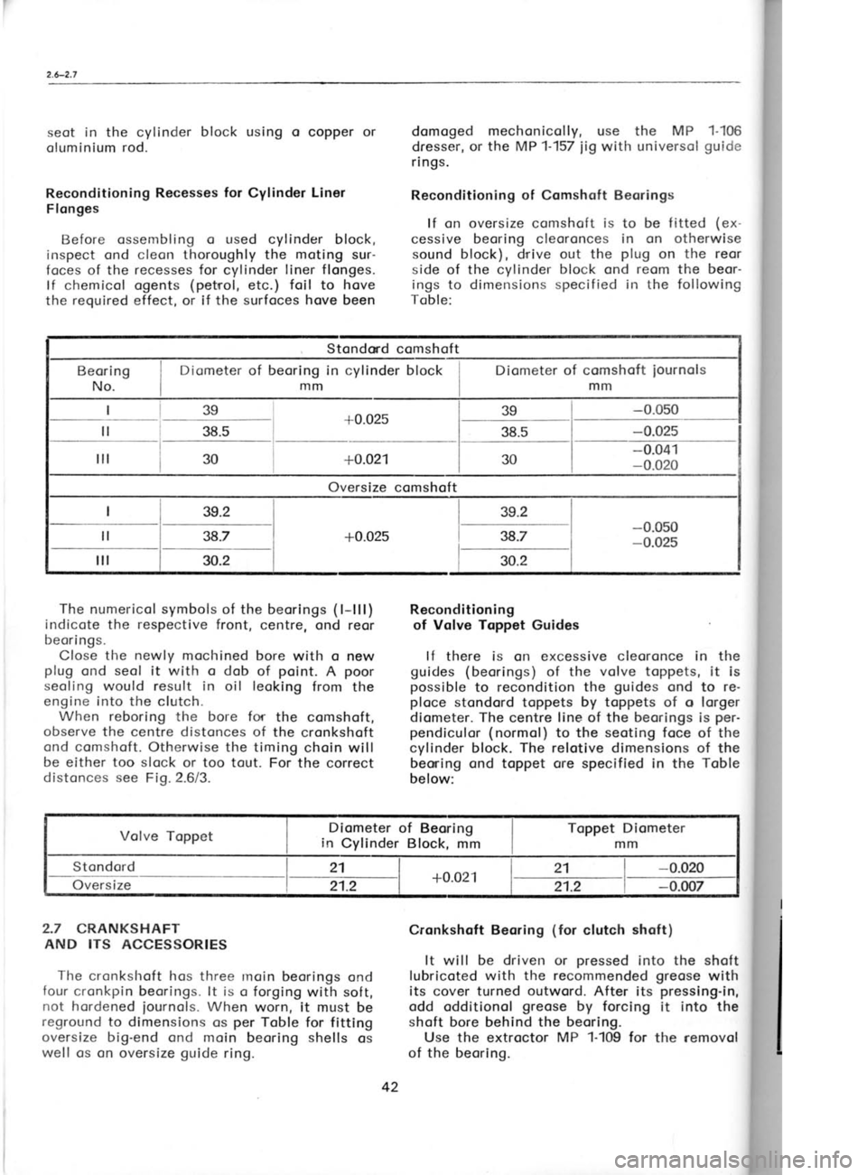
Reconditioning of Comshqft Beorings
lf on oversize
comshoft is to be f itted (ex-
cessive beoring cleoronces in on otherwise
sound block), drive out the plug
on the reor
side of the cvlinder block ond reom
the beor-
ings to dimensions specif ied in the following
Toble:
-0.025To
Grind
For grir
shoft by t
between 1
'Ihe
reor
ond there
for detoils
beoring.
For grir
prepored
clomped t,
pins must
Externol Col
Nomir iourn
Stondord
1st regrin
2nd regrin
3rd regrin
Stondond comshoft
Diometer of beoring in cylinder block
mm
+0.02s
38.5
+0.021
Oversize comshoft lsg
l-
38s-
l-;- -0.041
-0.020
The numerical symbols of the beorings (
l-lll)
indicote the respective
front, centre, ond reor
beari ngs.
Close the newly
mochined bore with o new
plug ond seol
it with o dob of point.
A poor
seoling would result in oil leoking
from the
engine into the clutch.
When reboring the bore for
the comshoft,
observe the centre distonces of the cronkshoft
ond comshoft. Otherwise the timing choin will
be either too slock or too tout. For the correct
distonces see
Fio. 2.6/3. Reconditioning
of Volve Toppet Guides
lf there is on excessive cleoronce in the
guides (beorings) of the volve toppets,
it is
possible to recondition the guides
ond to re-
ploce stondord toppets by toppets
of o lorger
diometer. The centre line of the beorings
is per-
pendiculor (normol) to the seoting foce
of the
cylinder block. The relotive dimensions
of the
beoning ond toppet ore
specified in
the Toble
below: o
L_r
_-L1il I toi .ll
-t
QZt0.l -T-
zi
A'ry
@)
2.7 CRANKSHAFT
AND ITS ACCESSORIES
The cronkshoft hos three rnoin beorings ond
four cronkpin beorings. lt is o forging with sof t,
not hordened iournols. When
worn, it
must be
reground to dimensions os per
Toble for fitting
oversize big-end ond moin beoring shells
os
well os cn oversize guide
ring. Cronkshoft Beoring
(for
clutch shoft)
It will be driven or pressed
into the shoft
lubricoted with the recommended greose
with
its cover turned outword.
After its pressing-in,
odd odditionol greose
by forcing it into the
shoft bore behind the beoring.
Use the extroctor MP 1-109 for
the removol
of the
beoring. Diometer of comshoft
iournols
mm
_ =l__i tl
Volve Toppet Diometer
of Beoring
in Cylinder Block, mmToppet
Diometer
mm
Stondord
on;rsizt- 21
+0.021 21
-0.020
21.2 21.2-0.007
42 4th
Page 46 of 238
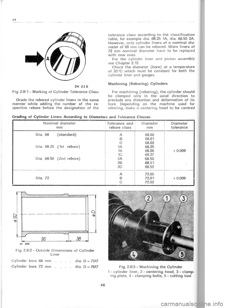
DK 626
Fig.2.911- Morking of Cylinder Toleronce
Closs
Grode the rebored cylinder liners in the some
monner while
odding the number of the re-
spective rebore before the designotion of the
Dio. 68 (stondord)
68.25 (1st
rebore)
68.50 (2nd
rebore)
Dio.72
Fig.2.912 -
Outside Dimensions of Cylinder
Liner
Cylinder bore 68 mm
Cyf inder bore 72 mm toleronce
closs occording to the clossificotion
toble, for exomple dio. 68.25
1A, dio.
68.50 24.
However, only cylinder liners of o nominol dio'
meter of 68 mm con be rebored. Worn liners of
72 mm nominol diometer hove
to
be reploced
with new ones. For the cylinder liner otrd pistotr
ossembly
see Chopter 2.12.
Check the diometer (bore)
ot o temperoture
of 20oC which must be constont for both the
cylinder liner ond gouges.
Mochining (Reboring)
Cylinders
For mochining (reboring),
the cylinder should
be clomped only in the oxiol direction to
preclude ony distortion
ond deformotion of its
bore. Depending on the mochine
used for
reboring, moke o
centering heod to be centred
68.00 68.01
68.02
68.25
68.26 68.27
68.50 68.51
68.52 +
0.009
72.OO 72.O1
72.O2 + 0.009
Fig.2.9/3 -
Mochining the Cylinder
1- cylinder liner, 2 -
centering heod, 3- clomp.
ing plote, 4 -
clomping bolts, 5 -
cutting tool
A
B
c
1A
1B
1C
2A
28
2C
AB
c
dio. D :75f7
dio. D:76t7
46
Groding of
Cylinder Liners
According to Diometers ond Toleronce
Closses
Nominol diometer mm Toleronce
ond I
rebore closs I IDiometer
mm Diometer
toleronce
Page 50 of 238
{
Smoll End ond
Big End Alignment
A misolignment of the centre line
of the
smoll-end bush ond big-end beoring
or the bore
for the big-end
beoring shells must never ex-
ceed 0.03
mm per 'lO0
mm of the connecting
rod length. For checking
ond olignment use
the
MP 1-102 or 1-159 f ixture.
Insert the odiusting pin
into the fixture ond
set both its diol indicotors to
zero. Clomp the
connecting rod without shells
into the fixture,
threod the pilot
pin
in it, ond swing
down the
connecting rod. The recdings
of the diol indi-
cotors will
show ony misolignment of the
smoll
ond big end. The moximum misolignment must
not exceed 0.03
mm os olreody mentioned.
Check for misolignment in two plones by tilting
the diol indicotors.
Two pilot
pins ore supplied, one with o
di-
ometer of 20 rnnr. the
other with o diometer of
20.05 mm, to motch the gudgeon
Pins.
To Motch Connecting Rod
with Gudgeon Pin
ond Cronkshoft
With regord to the reciprocoting movement
of the piston,
the gudgeon pin must hove
the
smollest possible
cleoronce in the
connecting
rod small end (ony lorger cleorcnce results
in
pin knocking). Therefore
select from
severol
gudgeon pins
one which will
be o close running
fit in the smoll-end
bush. lf no suclr pin is
ovoiloble, reom
tlre bush but never exceed the
moximum toleronce limits.
An oversize buslr lros to be
reomed to o nom-
inol diometer of 20.05 mm. For
the respective
dimensions refer to
the Toble supplied with
gudgeon pins. The big"end
beorings
i:;hells)
inouta be
selected occording to the nominol
diometer of the cronkpin. The
shells lrove no
diometer ntorking
oncl hove to be identif !ed
by meosuring their woll thickness with o mi'
crometer.
Motching Big-end Beoring
shells
with Cronkpins
MotchingCronkpin o"|,,n"iifl",,l ro,u,on
nominol diometer
1 thick"ness
mm
mm mm
45 (stondord)
44.75 (1st
regrinding)
44.50 (2nd
regrinding)
44.25 (3rd regrinding)
44 {:lttr regrinding) 1.490
1.615
1.740
1.865
1 990 0.007
Numericol lderrtif icotion of
Connecting Rods
For better identificotion, {igures con
be
stomped on the bosses of
the connecting rod
big end ( see Fig 2 11
1) . The f igures corre-spond with
the
number of the respective
gVtin-
derwithwhich theconnecting rod
is ossembled.
When replocing o connecting rod,
provide the
new connecting rod
with its very some identi-
ficction numbel. Stomp
the figures os much
toword the for end of the boss os possible to
ovoid fouling the loterol guide foce.
2.12 CYLINDERS, CONNECTING RODS
AND PISTONS
o) Only o cylinder (liner)
ond piston of
equot
'
diometer ond the some toleronce closs con
be ossembled qs
s unit.
b) Theengine cs qn
ossembly unit con befitted
cnly with cylinder liners ond pistons
of the
some diometer, the pistons being
of the
some weight grnLtp.
The inclividuol cylinder'cnd-piston qssemblies
con be, however, of dif
ferent toleronce
closses. On the othe'r hond, connecting rods
of only the sqme weight group
con be used-
These ore the cc;tditions for
the correct op-
erotion of pistons in the
cylinders ond for the
correct boloncing of the cronk mechonism.
For detoils concerning dimensions (diometers),
toleronce closses (cylinder liners, pistons) ond
weight groups
(connecting rods ond pistons)'
refei to fhe chcpters deoling with
the
individuol
pc|rts"
To Assembie Cylinder Liner
with Piston
qnd Connectirrg Rod
1. Toke cylinder liners ond pistons with
motching dinrensions, i. e.
cylinder liners of the
some boie (they need
not be necessorily of the
scrme toleronce closs), pistons
of the some
cliometer <,nrl tcieronce closs
to motch those of
the cvlinclr:i iitrers
ond of the sonre weight, oncl
connectitrct rorls,
tlle twtl weiglrt
cl roLr PS.
lti''
DK 1161 2.
1
OCCorl Selec'
cyl i nd
tolpro
the (
motch Son
pin or
gudge
in wh
suitob
bush.
Mor
respor
with v
meric<
Rod'.
3.L
the gr-
80"c i Sme
home
some
threod
Pin, o
circlip
on thr
pressi I
Fit
hole ir
the orr
4.F
or exp
detoils
the ri
groove
5- Pr
the crc
ond co
2.13 I
In or
ter ist ic
coms o
comsh<
c leoror
the cor
Volve '
with
lntoker
open be
close o
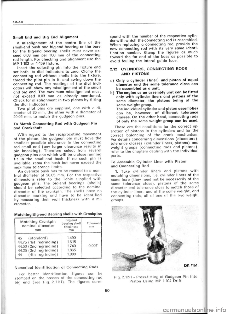
Fi,c 2.1211 -
Press'f ittirrg
of Gudgeon Pin into
Piston Usinq MP 1-i04
Drift
50
Page 86 of 238
1-
in the
other groove.
Chose the ring olso with
regord to toleronces cvoiloble
in one closs of
the rings os mentioned in the previous
Pqro-
groph. Check the cleoronce of the geor with
the oid of o diol indicotor.
Then remove the geor
including the friction
ring in the second groove
of the shoft.
7. Ploce the lock of the 1st' ond 2nd'speed
synchron izing clutch on the bench with
its
teeth downword. lnstoll
springs in the clutch
core securing them with greose
ogoinst folling
out ond insert the clutclr core with the shorter
side of the inner heod on
top in the respective
geor. Locote bclls (dio. 1ir
in.) on the springs, com-
p,ress the springs with
the fingers or using
o suitoble rod, cnd fit
the complete core
itrto
the geor.
8. Hoving thus osembled the synchronizing
clutch lock, instoll the synchronizing ring
fronr
the opposite side of the geor.
Now threod the
lock on the oiled shoft
with the geor focing
owoy from the shoft.
9. Instoll in position the
previously selected
friction ring with its groove
focing owoy from
the shoft (toword
the geor)
ond insert the
synchronizing ring into the fitted lock of the
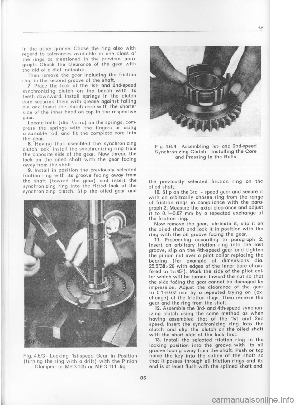
synchronizing clutch. Slip the oiled geor ond Fig.4.6la
-
Assembling 1st' ond 2nd-speed
Synchronizing Clutch -
lnstolling the Core
ond Pnessing in the Bolls
the previously
selected friction ring on
the
oiled shoft. 10. Slip on the 3rd -
speed geor
ond secure it
with on
orbitrorily chosen ring from the ronge
of friction rings in complionce with the poro-
groph 2. Meosure the oxiol cleoronce ond odiust
it to 0.1*0.07 mm by o repeoted exchonge of
the friction ring. Now remove the geor,
lubricote it,
slip it on
the oiled shoft ond lock it in position with the
ring with the oil groove
focing the geor.
11. Proceeding occording to porogroph 2,
insert on orbitrory friction ring into the lost
groove, slip on the 4th-speed geor
ond tighten
the pinion
nut over o pilot
collor replocing the
beoring (for
exomple of dimensions dio.
25.5/38x26 with edges of the inner
bore chom-
fered to 1x45o). Mork the side of
the pilot
col-
lor which will be
turned toword the
nut so thot
the side focing the geor
connot be domoged by
impression. Adiust the cleoronce of the geor
to 0.1+0.07 mm by o repeoted trying
on (ex-
chonge) of the friction rings. Then remove the
geor ond the ring from the shoft.
12. Assemble the 3rd- ond 4th-speed synchon-
izing clutch using the some method os when
hoving ossembled thot of the 1st ond 2nd
speed. lnsert the synchronizing ring
into the
clutch ond slip the clutch on the oiled shoft
with the short side of the lock first.
13. Instoll the selected friction
ring in the
locking position
into the groove with its
oil
groove focing owoy from the shoft. Push or top
home the key into the spline of the shoft so
thot it posses
through oll friction rings ond its
end is ot leost flush with the splined shoft end.
Fig.
4.6/3 -
Locking 1st-speed Geor in Position
(turning the ring with o drift) with the Pinion
Clompecl in MP 3-105 or MP 3111 Jig
86 Fig.
4.(
Page 133 of 238
tr
c
\
c'
pl
r€
o1.
tt pl
tt
r€
ol
w
ot
iu
ol
dt
is
ol
sl
Rr
ot
th
th
c0
c0
Broke
Shoes ond Broke Drums
When refitting
o broke shoe with o portiolly
worn lining moke sure thot it hos o thickness
sufficient to lost till the periodic
inspection
(ofter every 20,000 kilometres). The new lining
is 5 mm thick. When it is worn down to 1.5
to 'l
mm (4
to 3.5 mm when meosured
with the
shoe), the broke shoe hos to be reploced
with
o new.or
o reconditioned
shoe with glued-on
new lining. Be sure to reploce
the respective
broke shoes in both wheels to preserve
o uni-
form broking effect.
Speciol glues or cements
ond hordening ot
high temperotures
ore required when relining
the broke shoes so thot this
iob con
be done in
speciolized repoir shops
only. For informotion,
opply to the broke monufocturer -
Autobrzdy
Not. Corp., Joblonec
nod Nisou.
Broke drums are grey
cost-iron costings. Their
unequol weor
con be rectified
by mochining to
o 231 mm diometer.
No tool morks must be left
on their surfoce
which hos to be perfectly
smooth. The olignment deviotion
ond mochin-
ing toleronce should
not exceed 0.1 mm. The
moximum permissible weor is up Lo 232
mm in
diometer.
Only broke drums
with on identicol
diometer
ore permitted
to be mounted on one ond the
some oxle.
9.2 FRONT BRAKE
ASSEMBLY
Disnrontling ond Reossembly
1. Detoch
the broke fluid supply piping
from
the broke. Absolute cleonliness is o must.
Otherwise dirt ond foreign
motterwill penetrote
into the piping.
2. Renrove bolts lrolding
down the broke yoke
crnd lift owoy rlre broke
ossembly.
3. Use the MP 6-132 gouge
to set correctly
the broke (new
or repoired)
on reinstollotion.
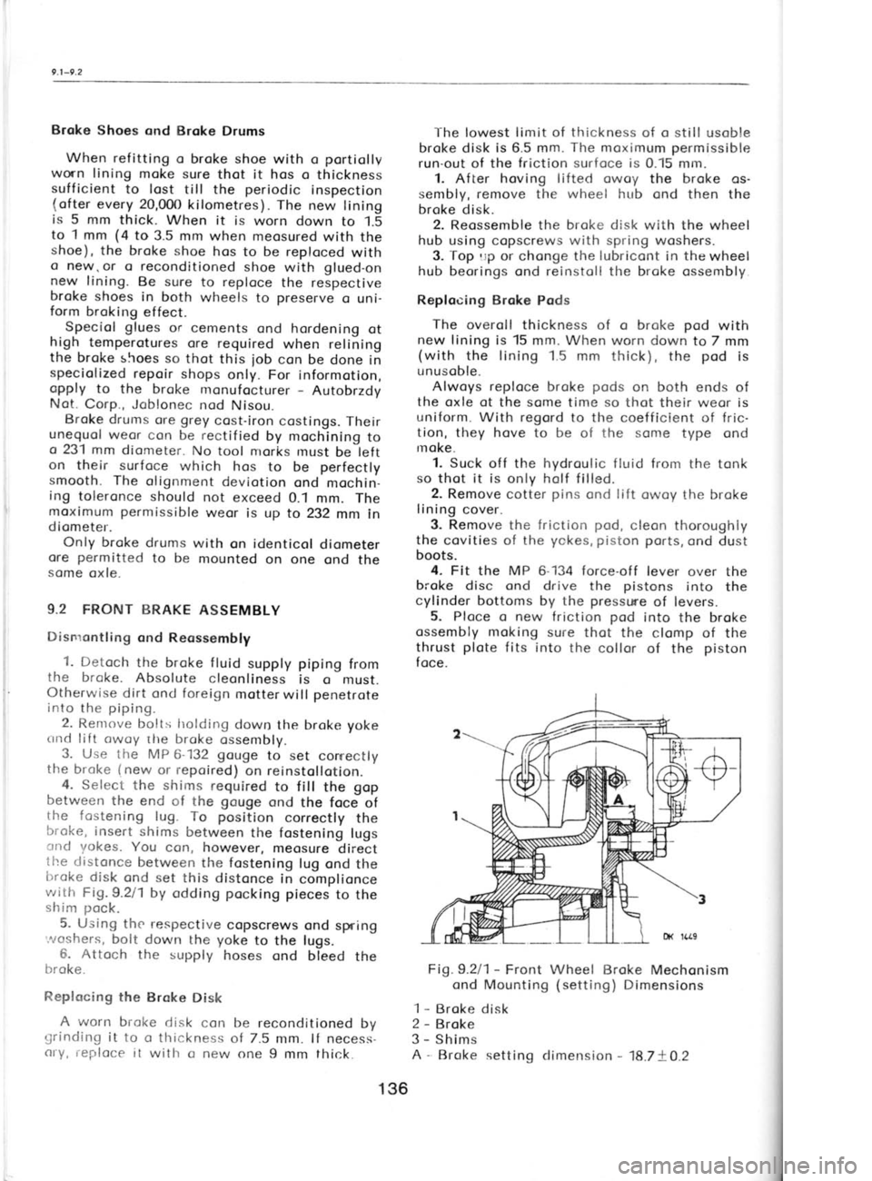
4. Select the shims required
to fill the gop
between the end of the gouge
ond the foce of
the fostening lug.To position
correctly the
broke, insert shims
between the fostening lugs
cnd yokes. You con, however,
meosure direct
the distonce
between the fostening
lug ond the
trroke disk
ond set this distonce
in complionce
with Fig. 9.211 by odding pocking
pieces
to the
shim pock.
5. Using the respective
copscrews ond spring
'.^roshers, bolt down the yoke
to the lugs.
6. Attoch the supply hoses ond bleed
the
broke.
Replocing the Brake
Disk
A worn brol
grinding it to o thickness
of 7.5 mm. lf necess-
cry, reploce it with o new one 9 mm thick. The lowest
limit of thickness
of o still usoble
broke disk is 6.5 mm. The
moximum permissible
run-out of the friction surfoce is
0.15 mm.
1. After hoving lifted owoy
the broke os-
sembly, remove the wheel hub
ond then the
broke disk. 2. Reossemble the broke disk
with the wheel
hub using copscrews with spring
woshers.
3. Top
rrp or chonge the lubricont
in the
wheel
hub beorings ond reinstoll the broke ossembly
Replocing Broke Pods
The overoll thickness of o broke pod
with
new lining is 15 mm. When worn down to 7 mm
(with the lining 1.5 mm thick), the pod
is
unusoble.
Alwoys reploce
broke pods
on both ends of
the oxle of the some time so
thot their weor is
uniform. With regord to the coefficient of fric-
tion, they hove to be of the some
type ond
rnoke.
1. Suck off the hydroulic fluid from the tonk
so thot it is only holf filled.
2. Remove cotter pins
ond lift
owoy the broke
lining cover.
3. Remove the friction pod,
cleon thoroughly
the covities of the yokes, piston
ports,
ond dust
boots.
4. Fit the MP 6-134 force-off lever over the
broke disc ond drive the pistons
into the
cylinder bottoms by the presswe
of levers.
5. Ploce o new friction pod
into the broke
ossembly moking sure thot the clomp of the
thrust plote
fits into the collor of the piston
foce.
Fig.9.2l1- Front Wheel Broke Mechonism
ond Mounting (setting)
Dimensions
1 -
Broke disk
2 -
Broke
3 -
Shims
A -
Broke setting climension -
18.7+O.2
136
Page 175 of 238
I
I
I
s
I
I
I
t
(
(
t
l
,
t
T c
R
L D
v Ir
1' 2
3
orotely
(
screen the other one) . With lef t
directionol heodlomps,
the borderline deviotes
towords the other
side.
lf the heodlomps ore neorer to the woll thon
the soid
5 metres, decreose the meosure indi-
coting the
deviotion of the light ond
dorkness
bordeiline from the
height of the heodlomps
obove the ground in the
direct proportion to
the
decreose of
tfre distonce, for
exomple when
plocing the cor 2.5 metres
from the woll, de-
creose the deviotion bY holf.
Light proiections "A"
ond "B"
correspond to
the spocing of heodlomPs on
the cor ond they
hove the following dimensions:
Heodlomps, dio. 160
mm 1,030
mm
Duol heodlomps, dio.
130 mm 1,114
mm
Auxiliory heodlomps, dio.
130 mm 790 mm
When odjusting the heodlomps, the cor must
be empty ond the
tyres must be correctly in-
floted. Hologen heodlomps should
not be left
switched on for too long o period os they build
up heot if not cooled by heod-on
oir blost when
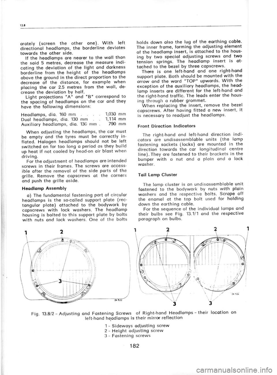
driving. For lhe odiustment of
heodlomPs ore intended
screws in their fromes. The screws
ore occess'
ible ofter the removol of the side ports
of the
grille. Remove the copscrews of the corners
ond push
the grille
oside.
Heodlomp Assembly
o) The fundomentol fostening
Port of
circulor
heodlomps is the
so-colled support plote
(rec-
tongulor plote)
ottoched to the bodywork by
copscrews with lock woshers. The
heodlomp
housing is bolted to this suPPort plote by bolts
with nuts ond lock woshers. One of the bolts holds
down olso the
lug of the eorthing coble-
The inner frome,
forming the
odiusting element
of the heodlomp insert, is ottoched
to the
hous'
ing by two speciol odiusting screws
ond two
tension springs. The heodlomp insert
is ot'
toched to
the bezel by
three copscrews.
There is one left-hond ond
one right-hond
support plote.
Both should
be mounted with the
oriow ond the word "TOP"
upwords. With
the
exception of the ouxiliory heodlomps, the
heod'
lomp inserts ore different for
the left-hond ond
the right-hond troffic. The leods
enter the hous-
ing through o
rubber grommet.
When r-eplocing the insert, remove
the bezel
copscrews. After
hoving fitted o new insert, it
is necessory to reodiust the
heodlomps.
Front Direction Indicotors
The right-hond ond
left-hond direction indi-
cotors ore undisossembloble units
(the
lomp
fostening sockets (locks) ore
mounted in the
direction towords the cor longitudinol centre
line). They ore fostened to their brockets in the
bumper with o nut ond o ploin ond
o lock
wosher.
Toil Lomp Cluster
The lomp cluster is on undisossembloble unit
fostened to
the bodywork by
nuts with ploin
woshers ond the
respective bolts.
Scrope off
the enomel ot the
top bolt used for holding
down the eorthing coble.
For the sequence
of the individuol lomps ond
their bulbs see Fig. 13.111 ond the respective
porogroph on bulbs.
Fig. 13.812 -
Adiusting ond
Fastening Screws of Right-hond Heodlomps -
their locotion
on
left-hond he-odlomps is their
mirror ref lection
1 -
Sidewoys odiusting screw
2 -
Height odiusting screw
3 -
Fostening screws
182
Page 212 of 238
I-
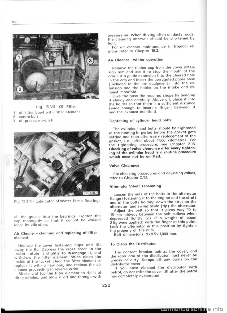
.'t Fig.
15.3/3 -
Oil Filter
oil f ilter bowl
witlr f ilter
element
centre-boll oil pressure
switclr pressure
oir. When driving often
on dusty roods,
ihe cleoning intervols
should
be shortened by
holf. For oir cleoner mointenonce in tropicol
re'
gions refer to
ChoPter 16.2.
Air Cleoner -
winter oPerotion
Remove the rubber
cop from
the cover exten-
sion orm ond
use it to stop the mouth of
the
orm. Fit o guide extension into
the cleored hole
in the ornr ond
insert the
corrugoted poper hose
(included in the
cor equipment) into
the
ex-
iension ond
the holder on the
intoke ond
ex-
houst monifold.
Give the
hose the required shope by
bending
it slowly ond corefully. Above
oll, ploce
it into
the holcier so thot
there is
o suff icient distonce
(wide enough to
insert o
finger) between it
crnd the exhot-tst monifold.
Tightening of
cYlinder heod bolts
The cylinder heod
bolts should be tightened
in the running-in period before
the gosket gets
settled ond then
ofter every replocement of the
gosket, i.e., ofter
obout 1,000
kilometres' For
itre tightening procedure,
s9e
Chopter
-2'16'
Check'ilg of vilve
cleoronce ofter
every tighten'
ing of tlie
cylinder heod
is o
routine procedure
which must not be omitted.
Volve Cleoronce
For checking procedures
ond odiusting volues,
refer to ChoPter 2.13.
Alternotor V'belt
Tensioning
Loosen the
nuts of the bolts
in the olternotor
f longe (fostening
it to
the engine ond
the strut)
ond'of itre
bottJ holding down
the strut on
the
olternotor, ond
swing
oside (tip)
the olternotor'
Adiust the
belt so
thot it gives
woy 10- to
15 mm midwoy between the
belt pulleys
when
depressed lightly (ot
if o- weight of obout
2 kg were opplieal with
the
finger ot this point'
LoCk the
olternotor in
this position
by tighten-
ing properlY
oll the nuts.
Belt dimensions: 9x9.5x1,0O0 mm.
To Cleon the
Distributor
The contoct breoker points, the
cover, ond
the rotor orm
of the distributor must never
be
greosy or dirty. Scrope off
ony burns on the
distributor cover.
lf you hove
cleoned the
distributor with
oetrol, do
not ref it the cover till ofter
the petrol
hos comPletelY evoPoroted.
222
oll
the greose
into the beorings. Tighten
the
cop thoioughly so
thot it connot be worked
loose by vibrotion.
Air Cleoner -
cleoning ond
replocing of
filter
element
Unclosp the cover
fostening clips
and lift
owoy the lid. Depress the
cross broce in
the
1ock6t, rotote
it
slightly to disengoge it, ond
withdrow the filter
element. Wipe
cleon the
inside of the
iocket, cleon
the filter
element or
reploce it with o new
one, ond reclose the oir
cleoner proceeding
in reverse order.
Shoke ond
top the filtet element to
rid it of
clirt porticles, oncl
blow it off ond through with
Fiq.15314
-
Lubricotor of
Woter Pump Beorings