service SKODA 120 LSE 1980 Workshop Manual
[x] Cancel search | Manufacturer: SKODA, Model Year: 1980, Model line: 120 LSE, Model: SKODA 120 LSE 1980Pages: 238, PDF Size: 47.09 MB
Page 16 of 238

Lifting
the cor with o
Power iock -
When
r-rsing o service
Power iock, let the
cor rest on
the points
shown in Fi1.1.412.
To tow the cor, hook the towing rope on
to
the brocket under
the cor nose. Threod the pin
through the loop of the rope
ond the brocket
lugs ond secure the pin
with o cotter pin (both
thL pin
ond the cotter pin
ore included in the
cor occessories).
1.5 SPARE WHEEL
AND FUEL TANK
Spore wheel -
After having opened the
lug-
goge boot lid, pull the hondle of the spore
wheel corrier releose
rod.
The corrier is
re-
leosed ond swings
down (speciol equipment of
the cor includes
o sofety lotch behind the
bumper which hos to be pushecl
oside to
releose the corrier
) . After
hoving closed the corrier (by
lifting it),
push the releose lever under
the bumper to the
right os for os it will go.
Fuel tonk -
The filler neck with cop is in the
reor on the right-hond
side of the cor- lt con
be locked ond unlocked by meons of
the re'
spective key.
1.6 STARTING THE
ENGINE AND CHECKING
ITS CORRECT RUNNING
1. Moke sure thot the geor
lever is in its
neutrol position,
switch on the ignition (pos-
ition I on the switch box) ond wotch the
coming on of the oil pressure ond chorging
worning lights, i.
e. check the function of the
olternotor -
see the informotion in porogroph
4.
Prepore the engine
to its temperoture:
- Storting from cold in
the occelerotor pedol
- Storting from cold in
the occelerotor pedol
choke for
storting occording
winter -
do not touch
ond use the full choke
summer -
do not touch
ond use only holf of the
Fig. 1.5/1 Hondle ot
Rod (f ronr obove )Spcre
Wheel Lock
crnrl Safety Lotch -
Storting o wormed-up engine -
depress the
occelerotor pedol
slowly to tlre
toe-boord, do
not touch the choke
2. Depress the clutch pedol
(odvisoble
in
summer, necessory in
winter) ond stort
the
engine by turning the ignition key to position
ll.
Let go
of the key os soon os the engine fires
ond releose the occelerotor pedol
{if it hos
been
clepressed).
It the engine ,refuses
to fire, return the key
to the position "0"
ond rePeot the
storting
Pro-
cedure. lf the engine is wormed up, depress the
occelerotor pedol
to obout one third of its totol
trovel. lf the cold engine stolls even
ofter the
second ond third storting ottemPt, enrich the
storting mixture by quickly
depressing the
oc-
celerotor pedol
once or twice to holf of its
trovel during the next storting ottemPt.
Never let tlre storter motor run for more
thon
obout 5 seconds. Woit
some 5 seconds before
repeoting the storting.
Fuel is injected
by every quick
depression of
the occelerotor pedol
ond enriches the mixture
so thot it is difficult to ignite. lf the engine
is flooded, stort
it
with o fully depressed oc-
celerotor pedol.
3. Increose the engine speed corefully while
releosing the clutch pedol. lf the
engine shows
signs of stolling, depress
ogoin the clutch
pedol.
Relecse
L.ever
Fi.1.5t2 Fuel Tcrtrk Filler
Neck
16
Page 20 of 238
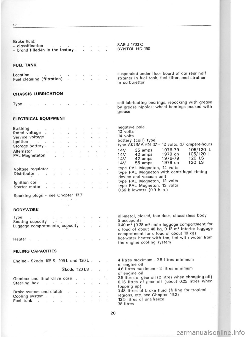
Broke
fluid:
- clossificotion
- brond filled-in in the foctrY -
FUEL TANK
Locotion Fuel cleoning (filtrotion)
CHASSIS LUBRICATION
TyPe
ELECTRICAL EQUIPMENT
Eorthing
Roted voltoge
Service voltoge
lgnition
Storoge botterY .
Alternator PAL Magneteton
Voltoge regulotor
Distributor
lgnition coil
Storter motor
Sporking plugs -
see ChoPter 137
BODYWORK
Type Seoting copocity
Luggoge comportments, coPocitY
H e oter
FILLING CAPACITIES
Engine -
Skodo 105 S, 105 L
ond 120 L
Skodo 120 LS
Georbox ond
finol drive cose
Steering box
Broke system
ond clutch
Cooling system
Fuel tonk SAE J
1703C
SYNTOL HD
190
suspended under
floor boord of cor reor holf
stroiner in fuel tonk,
fuel filter, ond stroiner
in corburettor
self-lubricoting beori
ngs,
by greose nipples;
wheel
greose
negctive pole
12 volts
14 volts repocking
with greose
beorings pocked
with
bottery (coil)
type
type AKUMA 6N 37 -
12 volts, 37 ompere-hours
14V 35 amps 1976-79
1O5/12O
L
14V 42 amps 1979 on
1O5/12O
L
14V 42 amps 1976-79
120 LS
14V 55 amps 1979 on
120
LS
type PAL Mogneton, 14 volts
type PAL Mogneton
with centrifugol timing
device ond vocuum unit
type PAL Mogneton, 12
volts
type PAL Mogneton, 12
volts
0.66 kilowotts (0.9
h. p.)
oll-metol, closed, four'door,
chossisless body
5 occuponts
0.40 mi (0.28
rn: moin luggoge comPortment for
q lood of obout
0 kg, 0.12 mr interior luggoge
comportment for
o lood of obout 10 kg)
hot-woter heoter
with fon, fed with woter
from
the engine cooling sYstem
4 litres moximum -
2.5 litres minimum
of engine oil
4.6 litres moximum -
3 litres minimum
of engine oil
2.5 lities of geor
oil (2 litres when
chonging oil)
0.16 litres of gecrr oil (obout
0.25 litres when
topping up)
O.4A titres of broke f
luid (f
illing for tropicol
regions, etc. see ChoPter 16.2)
12.5 litres of
ontif'reeze
38 litres 1.8 Tt(
BC
1. Ap
von ized
out o sL
2.tti
Threo
ENGINE
Connecti
Nut of c
Nut of c
Nut of vr
Nut of fr
Nut of c
Nut of si Nut of c'
Cylinder Bolt of c
Flywheel
Bolt of cr
Oil sump
Oil sump
Droin plu
Bolt of ft
Bolt of oi
Socket ol
Oil pressr
Sporking
CLUTCH Connectir Generol
20 Bolt
foste
Page 40 of 238
For the
instol lotion of the engine on the test
bench, we indicote the dimensions
of the en'
gine flonge ond flywheel. During broking, the
engine qnd
the engine oil must
be properly
cooled to preclude
exceeding the oPtimum
service conditions, i. e. woter temperoture
ofobout
80 to 90oC, ond oil temperoture of 12O"C
moximum -
see Chopter 2.5,
porogroph 51.
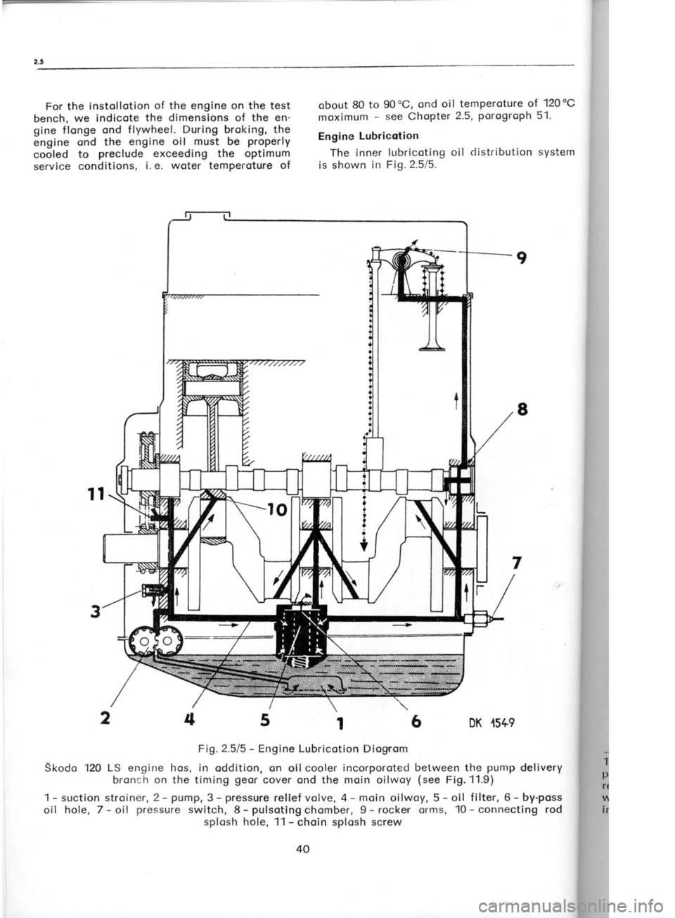
Engine Lubricotion
The inner lubricoting oil distribution system
is shown in Fig.2.5/5.
6 DK .r5+9 2.6
cYL
The cyl
mochined
the cronl
ports, forr
ore mode
B locks fo
72 mm di
I i ners.
Oilwoys, I
o) Befo
o new cyl
ossembled
blow thror"
b) Coot
pound or p
the oilwoy
c) Likev
into the e
pound or p,
of the
cyli
one (of
lo
limits indi
Ports) to er
d) Tighte
ot cylinder
under it.
e) Foster
the cop of
Fosten the
with o bolt
Fig.2.611 ond
1 -
choin gre
plug, 3 -
iniel
relief volve,
with cop, 6 -
inlet from o
ptug, I
9
8
7
5t
Fig.2.515 -
Engine Lubricotion Diognom
Skodo 120 LS
engine hos,
in oddition, on oil cooler incorporoted between the punrp
delivery
broncir on the timing geor
cover ond the moin oilwoy (see
Fi9.11.9)
srlctionstroiner,2-pump,3-pressurereliefvolve,4-moinoilwoy,5-oil filter,6-by-poss
hole, 7- oil pressure
switch, 8-pulsotingchomber, 9- rocker orms, 10-connecting rod
splosh hole, 11 -
choin splosh screw
4
2
4 t-
oil I
?
?
I
;
t
Page 117 of 238
5. Turning force
of box and column only. The
maximum permitted
turning force of the box and
column only (drag
link
attached to steering box
but allowed to slide freely
across idler) is 1.2kg
2.5lbs when test is carried out as in (2).
lf the force
is excessive, lubricate
universal joints
and check
thatthe drag link assembly is free to move. Repeat
test. lf still excessive remove
the steering box,
which can be removed
with the track rod still
attached.
TIME ALLOWANCE 5 mins.
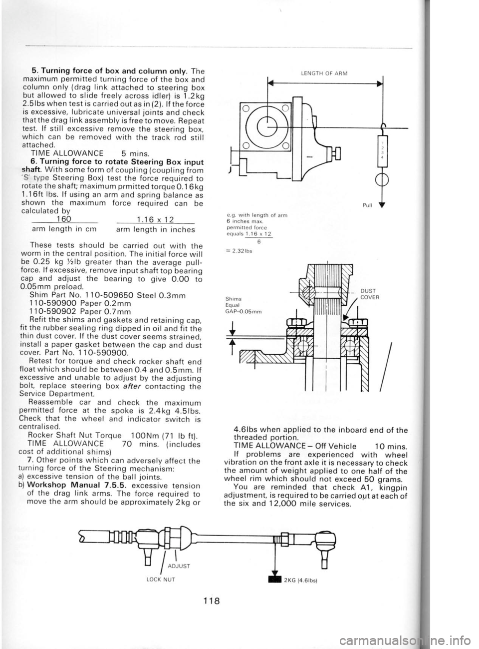
6. Turning force to rotate
Steering Box input
shaft. With some form
of coupling (coupling from
'S'
type Steering Box) test the force required to
rotate the shaft; maximum prmitted
torque0.1 6kg
1.16ft lbs.
lf using an arm and spring balance as
shown the maximum force required
can be
calculated bv
160
arm length
in crn
arm length
in inches
These tests should be carried out with the
worm in the central position.
The initial force will
be 0.25 kg %lb greater
than the average pull-
force. lf excessive, remove
input shaft top bearing
cap and adjust the
bearing to give
0.OO to
0.05mm preload.
Shim Part No. 11O-509650
Steel O.3mm
1 10-59O90O Paoer
O.2mm
1 10-590902 Paper
O.7mm
Refit the shims and gaskets
and retaining cap,
fit the rubber sealing ring
dipped in oil and f it the
thin dust cover. lf the dust cover seems strained,
install a paper
gasket
between the cap and dust
cover. Part No. 1 1O-5909O0.
Retest for torque
and check rocker
shaft end
float which should be between
O.4 and O.5mm. lf
excessive and unable to adjust by the adjusting
bolt, replace steering box after contacting
the
Service Department.
Reassemble car and check the maxtmum
permitted force at the
spoke is 2.4kg 4.5lbs.
Check that the wheel
and indicator switch is
ce ntra lised.
Rocker Shaft Nut Torque
100Nm (71
lb ft).
TIME ALLOWANCE
7O mins. (inctudes
cost of additional shims)
7. Other points
which can adversely
affect the
turning force of the
Steering mechanism:
a) excessive tension
of the ball joints.
b) Workshop
Manual 7.5.5. excessive tenston
of the drag link
arms. The force required to
move the arm should be approximately 2kg or e.g.
wrth length
of arm
6 inches
max.
permitted force
equals 1.16 x 12
6
= 2.32lbs
DUST
COVER
4.6lbs when applied to the inboard
end of the
threaded portion.
TIME ALLOWANCE -
Off Vehicte 1O mins.
lf problems
are experienced
with wheel
vibration on the front
axle it is necessary to check
the amount of weight applied to one half of the
wheel rim which should not exceed
50 grams.
You are reminded
that check A1, kingpin
adjustment, is required
to be carried ogt at each of
the six and 12,0OO mile services.
1.16 x12
UST
I
ADJ
UT LENGTH
OF ARM
118 2KG
{4.6lbs)
Page 169 of 238
L
i g)
Excitotion of the olternotor by o current
supply outside the cor is not permitted.
Agoin the semiconductors would suffer.
h) A blown chorging worning lomp must be
reploced immediotely with o new
one. Other-
wise correct excitotion of the olternotor is
not ensured. Use o new lomp of
the some
roting (or input), i.
e., 1.5
to 2 W.
i) Be sure thot there is
o perfect
electricol
connection on the connecting terminols ond
thot the olternotor
ond regulotor
ore properly
eorthed.
i) The
olternotor is oeroted, open. Therefore
toke core when woshing the cor thot woter
or cleoning ogents do not get
into it through
the venting holes.
Removing the Alternqtor
1. Disconnect the bottery.
2. Disconnect the olternotor leods. lt will be
helpful to remember the colour of one conductor
ond its connection for reinstollotion.
3. Remove oll ports
holding the olternotor on
the engine, ond lift owoy the olternotor.
Reinstolling the Alternotor
1. Cleon oll mounting surfoces.
For the olter-
notor mounting, see Chopter 2.3, por.42.
2. With the bottery
disconnected, insert the
conductors into the respective
connectors "M,,
ond "R"
(the conductors beor the some sym-
bols), ond fosten the remoining leod with o nut.
3. Reconnect the botterv. Alternotor
Disossembly -
Repoirs
1. Screw off the belt pulley
nut ond remove
the belt pulley
ond fon.
2. Lift the brushes with o hook proceeding
through the holes in the
commutotor end
shield
ond hold them in the lifted position
by wires
inserted into the shield through dio. 3 mm holes
under the terminols uM'
ond "Ru.
3. Mork the mutuol (relotive) position
of the
commutotor ond drive end shields ond seporote
the qlternotor
ofter hoving removed its clomping
bolts. The drive end shield remoins connected
with the stotor.
This disossembly will give
occess to the
brushes ond some
of the diodes. All other
iobs,
with the exception of the renewol of the beor-
ing, should be done by experts in speciolized
repcir shops -
see the note supplementing the
following porogrophs.
Alternotor Reossembly
1. Insert the circlip into the becring bore
in
the commutotor end shield.
2. Fit the drive end shield with beoring on
the rotor shoft.
3. Assemble the stotor with the rotor ond the
commutotor end shield. 4" Tighten the olternoior with clomping bolts
ond check the rotor for free rototion while
tightening the bolts.
5. Slip the spocer on to tlre shoft,
top the
key in position,
fit the fon ond belt pulley,
ond
tighten the entire ossembly using the nut with
spring wosher.
6. Pull out wires from the commutotor end
shield which hove been used to hold
brushes
in their lifted position.
Replocement of Beorings
The used beorings ore fullyclosed ond seoled,
ond they hove been filled in the foctory
with
lubricont to lost through their entire service life.
1. Pull the beoring off the rotor
using o suit-
oble puller.
When ref itting the beoring, press
it
on to beor on the shoft
collor-
2. Before removing the drive end shield
beor-
ing, f irst drill off the heods
of the flonge rivets
ond then drive the beoring out from
the outer
side of the drive end shield using o suitoble
mondrel (drift).
On reossembly,
close the beoring with the
flonge ond rivet the flonge to the shield.
Replocement of Diodes
The use of the removoble
diode block with
the individuol
corriers of the so-colled positive,
negotive, ond ouxiliory diodes, focilitotes con-
siderobly the replccement of ony defective
176
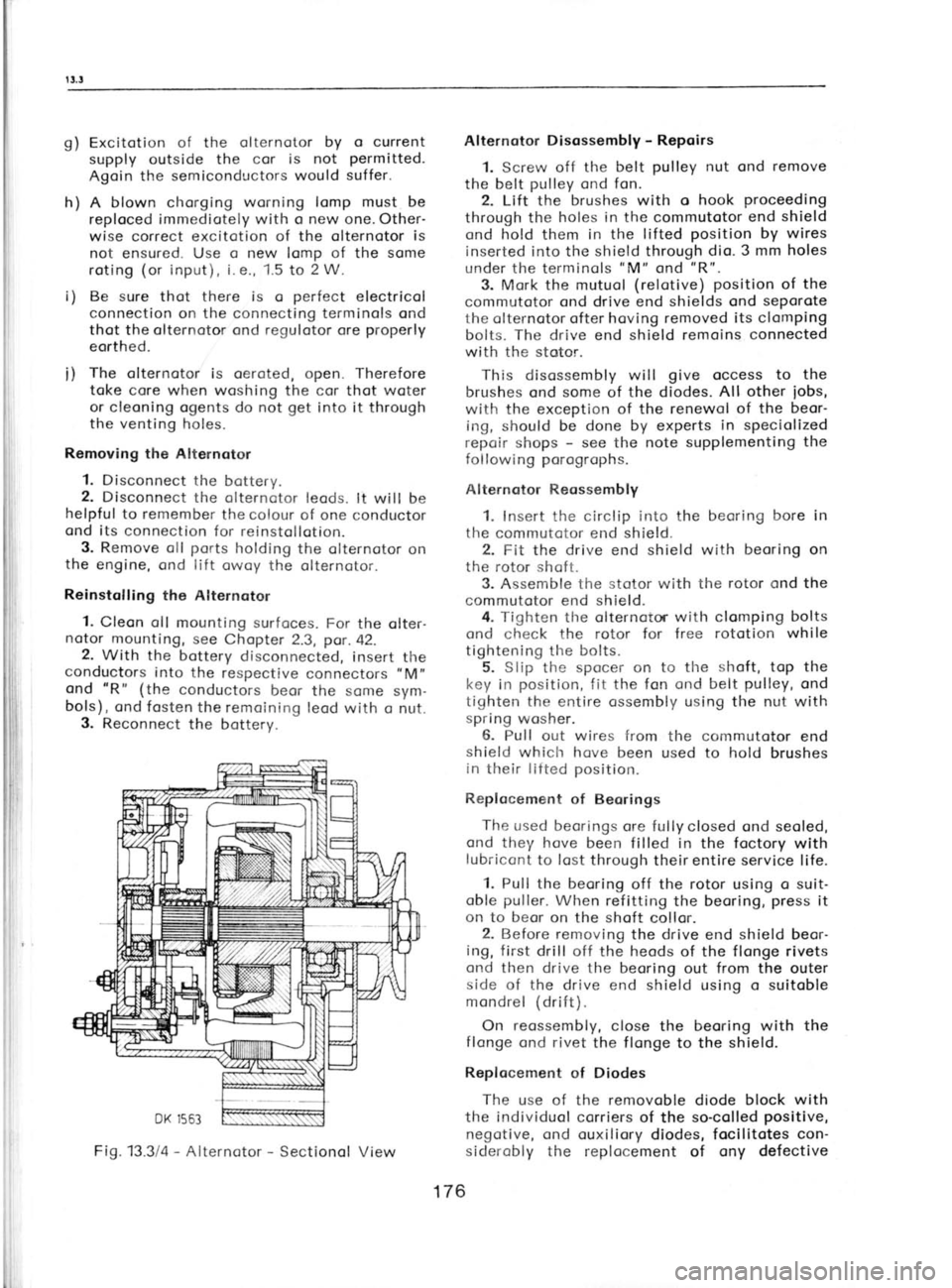
Fig.133la
-
Alternotor -
Sectionol View
Page 171 of 238
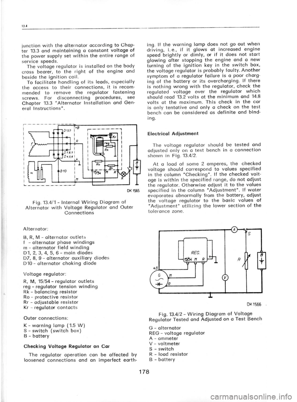
junction
with the olternoto,r occording to
Chop-
ier 13.3 ond mointoining
o constont voltoge of
tlre power
supply set within the
entire ronge
of
service speeds.
Tlre voltoge regulotor
is instolled orr the body
cross beorer, to
the right of the engine ond
beside the ignition coil.
To focilitote hondling
of its leods' especiolly
the occess to their
connections, it
is recom-
rrrended to remove the regulotor fostening
screws. For disconnecting procedures,
see
Chopter 13.3 "Alternotor
lnstollotion ond Gen-
erol lnstructions".
DK 1565
Fig.13.411- Internol
Wiring Diogrom of
Alternotol with
Voltoge Regulotor ond
Outer
Connections
Altenrotor: B, R, M -
olternotor outlets
f -
olternotor phose
windings
m -
olternotor field winding
D1,2,3, 4, 5, 6 -
moin diodes
D7, 8,9 -
olternotor ouxiliory diodes
D10 -
olternotor choking diode
Voltoge regulotor:
R, M, 15/54 -
regulotor outlets
reg -
regulotor tension winding
Rk -
boloncing resistor
Ro -
protective resistor
Rr -
odiustoble resistor
Kr -
regulotor contocts
Outer connections: K -
worning lomp (1.5
W)
S -
switch (switch
box)
B -
bottery
Checking Voltoge Regulotor
on Cor
The regulotor operotion con be offected by
loosened connections ond on imperfect eorth- ing.
lf the wsrning lomp does not go
o.ut when
driving, i. e., if it glows
ot increosed engine
speed brightly or dimly,
or if it does not stort
glowing ofter stopping
the engine ond
o new
iurning of the ignition key in
the switch box,
the voitoge regulotor
is probobly
foulty. Another
symptom of o regulotor
foilure is
o poor
chorg-
irrg of tlre bottery or its
overchorging.. lf there
is nothing wrong with the regulotor, check the
reguloted voltoge over the regulotor which
slrould reod 13.2 volts ot the
minimum ond 14.8
volts ot the moximunr. This check
in the
cor
is only tentotive ond only
o check on
the test
bench'con be considered os definite ond
bind'
i ng.
Electricol Adiustment
The voltoge regulotot- should be tested
ond
odjusted only on o test bench
in o connection
slrown in Fig. 13.412.
At o lood of some
2
onrperes, the checked
voltoge should correspond to
volues specified
in the column "Checking".
lf the checked volt-
oge is within the specified ronge, do
not odiust
the regulotor. Othenwise odiust it to the volues
specified in the column "Adiustment".
lf woter
evoporotes obnormolly from the bottery, odiust
the voltoge regulotor to the bosic volues of
"Adiustment" utilizing the lower section of
the
toleronce zone.
Fig.13.al2 -
Wiring Diogrom of
Regulotor Tested
ond Adiusted on
o
G -
olternotor
REG -
voltoge regulotor
A -
ommeter
V -
voltmeter
S -
switch
R -
lood resistor
B -
bottery DK
1566
Voltoge Test Bench
178
Page 210 of 238
tificotion
number, or in
words. For exomple
Mobiloil 30 is on oil in the SAE 30 viscosity
closs, Mobiloil Speciol belongs to the SAE
10 W/30 closs. We quote
the viscosity closs
symbol of oils identified
in this woy in brockets
following the oil brond (trode
nome).
Oils designoted by o doubled viscosity closs
symbol ore the so-colled multigrode oils. Their
complionce with viscosity clossificotion is ex-
pressed by the symbol before the froction line
progressively to the clossificotion expressed by
the symbol behind the froction line. Thus,
for
instonce, the SAE 10W/30 oil hos the properties
of the sAE 10w, sAE 20w120,
ond sAE 30
closs.
Czechoslovok oils
Motor oil M6 AD (SAE
30), M4AD (SAE
20W/
20), Mogul Super SAE 20W50,
Mogul Speciol
SAE 2OW/30
Modit Oil SAE 30 (M6
AD), Modit Oil SAE
2OWl2O (M4AD), Modit Oil Speciol
SAE 10W/
30, Modit Super SAE 10W/40
Foreign oils
Agip: Agip F. 1 Motor Oil HD SAE 10W/20,
2OWl30, 4Ol5O; Agip F. 1
Super Motoroil
10w/40,20wl50
BP: Energol HD SAE 40, 30, 2OW (2OW|?O),
10W; Super Visco-Stotic 10Wi30, 10W/40,
20wt20
Costrof : Costrol 40,
30, 20Wl2O, '10
W; Costrolite
(SAE 10W/30), XL (SAE 20W/50);
GTX
(SAE 10w/50)
Mobil: Mobiloil 40, 30, 2OWl2O,
10W; Speciol
(SAE 10W/30); Speciol 20W/50; Super (SAE
10w/so)
Shef l; X-100 40, 30, 2OWl20,
10W; Super (SAE
10w/so)
Other oils of foreign moke con be used if equi-
volent to the listed bronds, for
exomple, Avio,
Esso, Heno (Optimol
LD), INA (Delto TLX),
Noftogos (Golox GTX, Omnio) etc.
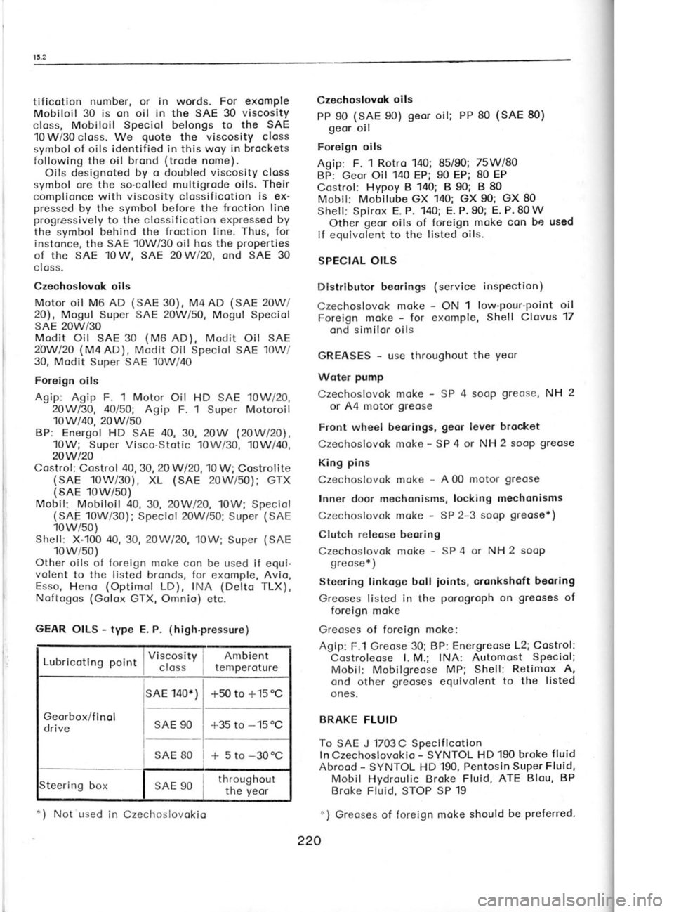
GEAR OILS -
type E. P. (high-pressure)
I Viscosity j Ambient
Lubricoting noint
I closs
! temperoture
sAE 140*) -r50
to +15 oC
Georbox/f inol
drive SAE
90
*35 to -15
oC
* 5 to -30oC
SAE 80
teering box SAE 90 throughout
the yeor Czechoslovok
oils
PP 90 (SAE
90) geor
oil; PP 80 (SAE 80)
geor oil
Foreign oils
Agip: F. 1 Rotro 140; 85/90; 75Wl8O
BP: Geor Oil 140
EP; 90 EP; 80 EP
Costrol: Hypoy B 140; B 90; B 80
Mobil: Mobilube GX 140; GX 90; GX 80
Shell: Spirox E. P. 140; E. P. 90; E. P. 80 W
Other geor
oils of foreign moke con be used
if equivolent to the listed oils.
SPECIAL OILS
Distributor beorings (service inspection)
Czechoslovok moke -
ON 1 low'pour-point oil
Foreign moke -
for exomple, Shell Clovus 17
ond similor oils
GREASES -
use throughout the yeor
Woter pump
Czechoslovok moke -
SP 4 sooP greose,
NH 2
or A4 motor greose
Front wheel beorings, geor lever
brocket
Czechoslovok moke -
SP 4 or NH 2 soop greose
King pins
Czechoslovok moke -
A 00 motor greose
Inner door mechonisms, locking mechonisms
Czechoslovok moke -
SP 2-3 soop greose*)
Clutch releose beoring
Czechoslovok moke -
SP 4 or NH 2 soop
greose* )
Steering tinkoge boll
ioints, cronkshoft
beoring
Greoses listed in the porogroph
on greoses
of
foreign moke
Greoses of foreign moke:
Agip: F.1 Greose 30; BP: Energreose L2; Costrol:
Costroleose l. M.; INA: Automost Speciol;
Mobil: Mobilgreose MP;
Shell: Retimox A,
ond other greoses
equivolent to
the listed
ones.
BRAKE FLUID
To SAE J 1703C Specificotion
ln Czechoslovokio -
SYNTOL HD 190 broke fluid
Abrood -
SYNTOL HD 190, Pentosin
Super Fluid,
Mobil Hydroulic Broke Fluid, ATE Blou, BP
Broke Fluid, STOP SP 19
r) Greoses of foreign moke should be preferred.
220
*)
Not used
in Czechoslovokio
Page 216 of 238
friction focing. lnodequote
ploy
results irr o too
short free trovel of the clutch pedol
ond on
olmost immediote clutch disengogement. Access
to the releose
cylinder con be goined
os de-
scribed in the previous porogroph
on clutch
lubricotion. Hold the rod protruding from
the
relose cylinder ond force
from it corefully the
releose lever, ogoinst which it is restingi
the
lever con be relieved by disengoging the ten-
sion (pull-off
) springs.
ln service, the forcing-off
must be ot leost
2 mm. Adiust it to 4
to 5 mm by odiusting the
length of the rod. After hoving
loosened the nut
on the rod
of the releose cylinder, rotote
the
releose finger to obtoin the correct rod
length.
Then retighten the nut, thus locking the releose
f inger in its position
on the rod.
lf the ploy
is correctly od justed,
the f ree
trovel of the
clutch pedol
pod should ronge
from 40 to 50 mm. lt should not be ollowed to
drop below '!0
to 15 mm. lf the described od-
justing procedure foils to bring the required
result, it is necessory to odjust the clutch
mech-
onism in occordonce with
informotion con
toined in Chopter 3.2.
Bleeding the Glutch Hydroulic System
The movement of the clutch pedol
is trons-
mitted hydroulicolly to the clutch releose cylin-
der. The couses ond symptoms of penetrotion
of oir into the hydroulic
system (similor
to the
broke hydroulic system) ore described in detoil
in the section deoling with brokes. The pro-
cedure of bleeding the clutch is the some os
wherr bleeding the brokes -
see Chopter 15.8.
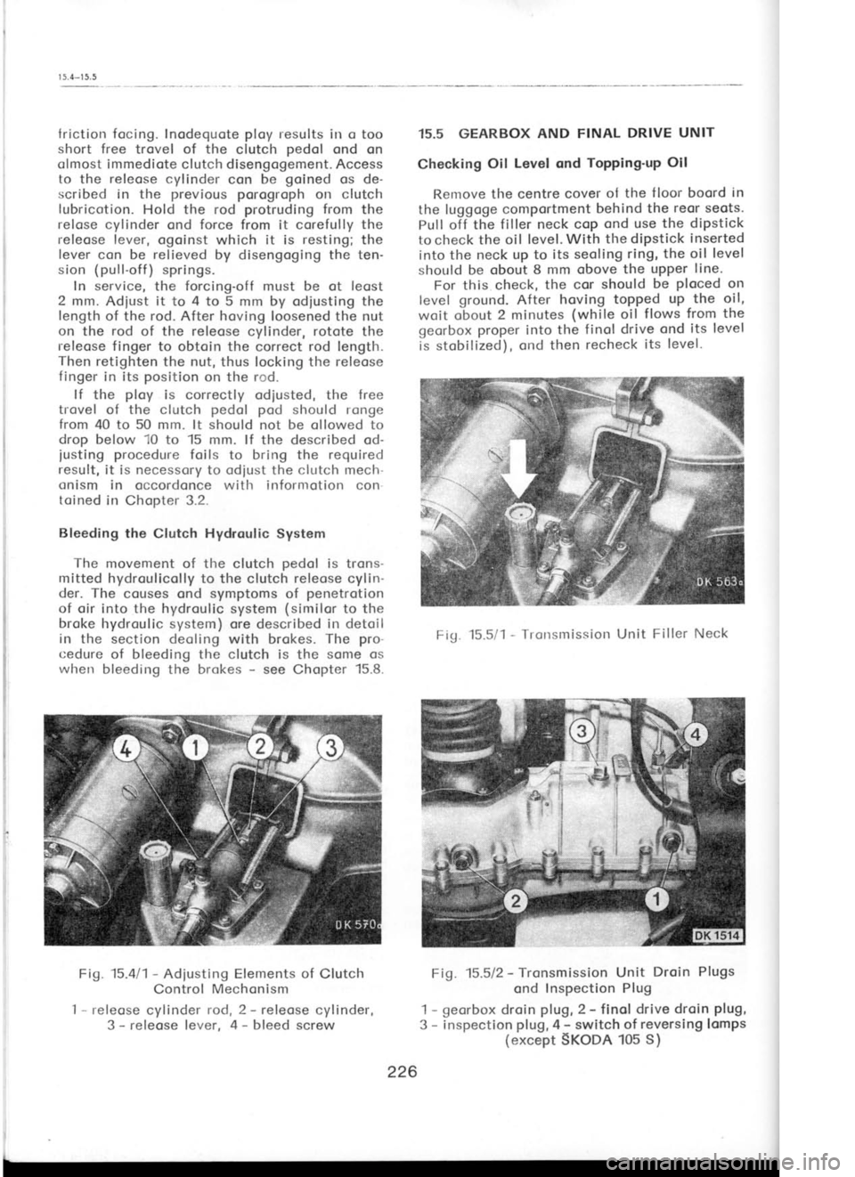
Fig. 15.411-
Adiusting Elements of
Clutch
Control Mechonism
I -
releose cylinder rod, 2 -
releose cylinder,
3 -
releose lever, 4 -
bleed screw 15.5 GEARBOX
AND FINAL DRIVE UNIT
Checking Oil
Level ond Topping'up
Oil
Renrove the centre cover ol the
f loor boord in
the luggoge comportment behind the
reor seots.
Pull off the filler neck cop ond use
the dipstick
to check the oil level. With the diPstick inserted
into the neck up to its seoling ring, the oil level
should be obout 8 mm obove the upper line'
For this check, the cor
should be ploced
on
level ground.
After hoving topped up the oil,
woit obout 2 minutes (while
oil flows from the
georbox proper
into the finol drive ond its level
is stobilized), ond then recheck
its level-
Fig. 15.5/1 -
Tronsmission Unit Filler Neck
Fig. 15.512 -
Tronsmission Unit Droin
Plugs
ond Inspection Plug
1 -
georbox droin plug,
2 -
finol drive droin plug,
3 -
inspection plug,
4 -
switch of reversing lcmps
(except SKoDA 105 S)
ffi
;rt'i,*
tiiffi
ii.! i;
br'ill
226