interior lights SKODA CITIGO 2013 1.G Owner's Manual
[x] Cancel search | Manufacturer: SKODA, Model Year: 2013, Model line: CITIGO, Model: SKODA CITIGO 2013 1.GPages: 176, PDF Size: 10.54 MB
Page 6 of 176
Table of Contents
Materials defect liability and ŠKODA warranty for
new cars5
Mobility warranty and ŠKODA extended
warranty.
6
Abbreviations
Using the system
Cockpit
9
Overview
8
warning lights and instruments
10
Instrument cluster
10
Multifunction display (MFA)
13
Warning lights
16
Unlocking and locking
22
Unlocking and locking
22
Central locking system
25
Remote control
27
Luggage compartment lid
28
Electrical power windows
30
Power sliding/tilting roof
31
Lights and visibility
33
Lights
33
Indoor Lighting
36
Visibility
37
Windscreen wipers and washers
38
Rear mirror
40
Seats and stowing
42
Front seats
42
Rear seats
45
Luggage compartment
46
Roof rack system
49Useful equipment50Storage compartments53
Heating and air-conditioning
57
Heating, ventilation and cooling
57
Heating
58
Air conditioning system
59
Communication and multimedia
63
Telephone and Move & Fun
63
Driving
Starting-off and Driving
66
Steering
66
Starting and stopping the engine
67
Brakes
68
Manual gear changing and pedals
70
Automated transmission
71
Running in
73
Economical driving and environmental
sustainability
74
Avoiding damage to your vehicle
78
Driving abroad
79
Assist systems
80
Brake assist systems
80
Parking aid
81
Cruise Control System
83
START-STOP
85
City Safe Drive
86
Safety
Passive Safety
90
General information
90
Correct seated position
91
Seat belts
94
Using seat belts
94
Inertia reels and belt tensioners
96Airbag system98Description of the airbag system98
Airbag overview
99
Deactivating airbags
101
Transporting children safely
103
Child seat
103
Fastening systems
105
General Maintenance
Vehicle care
108
Service intervals
108
Modifications, adjustments and technical
alterations
110
Washing your car
113
Taking care of your vehicle exterior
115
Taking care of the interior
118
Inspecting and replenishing
122
Fuel
122
Vehicles with CNG (compressed natural gas)
mode
123
Engine compartment
127
Engine oil
130
Coolant
132
Brake fluid
133
Vehicle battery
134
Wheels
138
Tyres and wheel rims
138
Winter operation
143
Do-it-yourself
Emergency equipment and self-help
144
Emergency equipment
144
Changing a wheel
145
Tyre repair
1483Table of Contents
Page 12 of 176
Using the system
Cockpit
OverviewDoor opening lever
24
Electrical power window in the driver's door
30
Central locking system
27
Electric exterior mirror adjustment
41
Air outlet vent
57
Operating lever:
› Turn signal lights and main beam, headlight flasher
34
›
Speed regulating system
83
Parking ticket holder
53
Steering wheel:
› With horn
› With driver’s front airbag
99
Instrument cluster: Instruments and warning lights
10
Operating lever:
› Multifunction display
13
›Windscreen wiper and wash system
38
Button for rear window heater
37
START-STOP button
85
Depending on equipment fitted:
› Operating controls for the heating
58
›Operating controls for the air conditioning system
59
Socket for the cradle for the Move & Funmultifunction device.
64
Warning light for the deactivated front seat passenger airbag
102
Interior rear-view mirror
40
Button for hazard warning light system
36
Front passenger airbag
99
Bag holder
55
Storage compartment on the front passenger side
54
Air outlet vent
57123456789101112131415161718192021Power window in the front passenger door30Door opening lever24
Light switch
33
Bonnet release lever
127
Regulator for headlamp beam adjustment for the headlights
34
Lever for adjusting the steering wheel
66
Ignition lock
68
Pedals
71
Regulator for left seat heating
44
Radio
Button for City Safe Drive system
86
Handbrake lever
70
Depending on equipment fitted:
› Gearshift lever (manual gearbox)
70
›
Selector lever (automated gearbox)
71
Storage compartment
55
Regulator for right seat heating
44
Note
■
Cars with factory-fitted radio are supplied with separate instructions for operat-
ing such equipment.■
The arrangement of the controls and switches and the location of some items
on right-hand drive models may differ from that shown in » Fig. 1 . The symbols on
the controls and switches are the same as for left-hand drive models.
2223242526272829303132333435369Cockpit
Page 29 of 176
Safe securing systemFirst read and observe the introductory information and safety warn-
ings
on page 25.
The central locking system is equipped with a safe securing system. The door
locks are blocked automatically if the vehicle is locked from the outside. The warning light flashes for around 2 seconds in quick succession, afterwards it be-gins to flash evenly at longer intervals. It is not possible to open the doors withthe door handle either from the inside or from the outside. This acts as an effec-
tive deterrent against attempts to break into your vehicle.
The safe securing system can be deactivated within 2 seconds by double locking
the vehicle.
If the safe securing system is not operating, the warning light in the driver door flashes for about 2 seconds fast, goes out and starts to flash evenly at longer in-
tervals after about 30 seconds.
The safe securing system is activated again the next time the vehicle is unlocked and locked.
If the vehicle is locked and the safe securing system is deactivated, the door can
be opened from the inside by a single pull on opening lever of the respective
door.
WARNINGIf the vehicle is locked from the outside and the safe securing system is acti-
vated, there must not be any person in the vehicle as it is then no longer pos-
sible to open either a door or a window from the inside. The locked doors
make it more difficult for rescuers to get into the vehicle in an emergency – risk to life!
Note
You will be informed that the safe securing system has been activated after the
vehicle has been locked by means of the message on the instrument clus-
ter display.
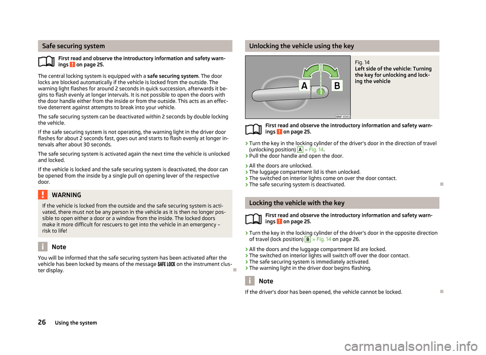
Unlocking the vehicle using the keyFig. 14
Left side of the vehicle: Turning
the key for unlocking and lock-
ing the vehicle
First read and observe the introductory information and safety warn- ings on page 25.
›
Turn the key in the locking cylinder of the driver's door in the direction of travel
(unlocking position)
A
» Fig. 14 .
›
Pull the door handle and open the door.
› All the doors are unlocked.
› The luggage compartment lid is then unlocked.
› The switched on interior lights come on over the door contact.
› The safe securing system is deactivated.
Locking the vehicle with the key
First read and observe the introductory information and safety warn-
ings
on page 25.
›
Turn the key in the locking cylinder of the driver's door in the opposite direction
of travel (lock position)
B
» Fig. 14 on page 26.
› All the doors and the luggage compartment lid are locked.
› The switched on interior lights will switch off over the door contact.
› The safe securing system is immediately activated.
› The warning light in the driver door begins flashing.
Note
If the driver's door has been opened, the vehicle cannot be locked.
26Using the system
Page 30 of 176
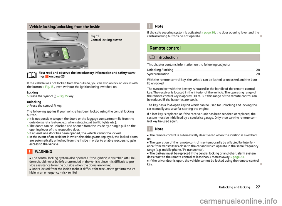
Vehicle locking/unlocking from the insideFig. 15
Central locking button
First read and observe the introductory information and safety warn-ings on page 25.
If the vehicle was not locked from the outside, you can also unlock or lock it with
the button » Fig. 15 , even without the ignition being switched on.
Locking
›
Press the symbol
» Fig. 15 key.
Unlocking
›
Press the symbol
key.
The following applies if your vehicle has been locked using the central locking button.
› It is not possible to open the doors or the luggage compartment lid from the
outside (safety feature, e.g. when stopping at traffic lights etc.).
› The doors can be unlocked and opened from the inside by a single pull on the
opening lever of the respective door.
› If at least one door has been opened, the vehicle cannot be locked.
› In the event of an accident in which the airbags are deployed, the locked doors
are automatically unlocked from the inside in order to enable rescuers to gain
access to the vehicle.
WARNING■ The central locking system also operates if the ignition is switched off. Chil-
dren should never be left unattended in the vehicle since it is difficult to pro-
vide assistance from the outside when the doors are locked.■
Doors locked from the inside make it difficult for rescuers to get into the ve-
hicle in an emergency – risk to life!
NoteIf the safe securing system is activated » page 26, the door opening lever and the
central locking buttons do not operate.
Remote control
Introduction
This chapter contains information on the following subjects:
Unlocking / locking
28
Synchronization
28
With the remote control key, the vehicle can be locked or unlocked and the boot
lid unlocked.
The transmitter with the battery is housed in the handle of the remote control
key. The receiver is located in the interior of the vehicle. The operating range of
the remote control key is approx. 30 m. But this range of the remote control can
be reduced if the batteries are weak.
The key has a fold-open key bit which can be used for unlocking and locking the
car manually and also for starting the engine.
If a lost key is replaced or if the receiver unit has been repaired or replaced, thesystem must be initialised by a specialist garage. Only then can the remote con-
trol key be used again.
Note
■ The remote control is automatically deactivated when the ignition is switched
on.■
The operation of the remote control may temporarily be affected by interfer-
ence from transmitters close to the car and which operate in the same frequency
range (e.g. mobile phone, TV transmitter).
■
The battery must be replaced if the central locking or anti-theft alarm system
does react to the remote control at less than 3 metres away » page 23.
■
If the driver door is open, the vehicle cannot be locked using the remote control
key.
27Unlocking and locking
Page 31 of 176
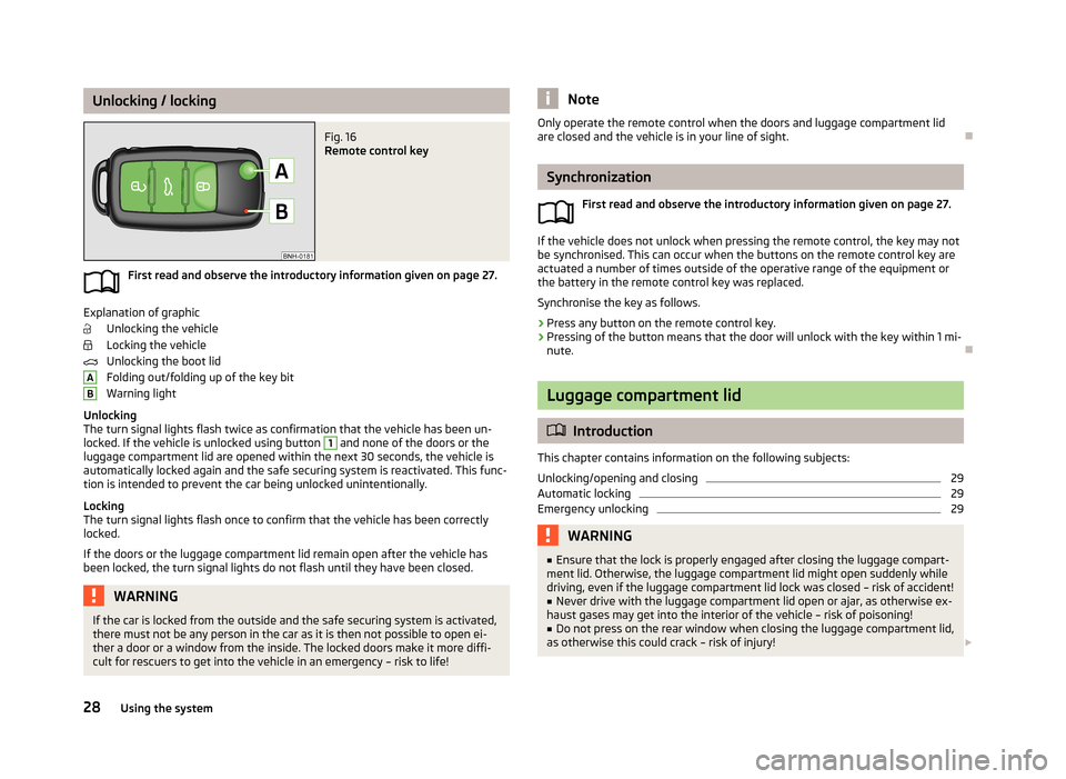
Unlocking / lockingFig. 16
Remote control key
First read and observe the introductory information given on page 27.
Explanation of graphicUnlocking the vehicle
Locking the vehicle
Unlocking the boot lid
Folding out/folding up of the key bit
Warning light
Unlocking
The turn signal lights flash twice as confirmation that the vehicle has been un-
locked. If the vehicle is unlocked using button
1
and none of the doors or the
luggage compartment lid are opened within the next 30 seconds, the vehicle is
automatically locked again and the safe securing system is reactivated. This func-
tion is intended to prevent the car being unlocked unintentionally.
Locking
The turn signal lights flash once to confirm that the vehicle has been correctly
locked.
If the doors or the luggage compartment lid remain open after the vehicle has
been locked, the turn signal lights do not flash until they have been closed.
WARNINGIf the car is locked from the outside and the safe securing system is activated,
there must not be any person in the car as it is then not possible to open ei-
ther a door or a window from the inside. The locked doors make it more diffi-
cult for rescuers to get into the vehicle in an emergency – risk to life!ABNoteOnly operate the remote control when the doors and luggage compartment lid
are closed and the vehicle is in your line of sight.
Synchronization
First read and observe the introductory information given on page 27.
If the vehicle does not unlock when pressing the remote control, the key may notbe synchronised. This can occur when the buttons on the remote control key are
actuated a number of times outside of the operative range of the equipment or
the battery in the remote control key was replaced.
Synchronise the key as follows.
›
Press any button on the remote control key.
›
Pressing of the button means that the door will unlock with the key within 1 mi-
nute.
Luggage compartment lid
Introduction
This chapter contains information on the following subjects:
Unlocking/opening and closing
29
Automatic locking
29
Emergency unlocking
29WARNING■ Ensure that the lock is properly engaged after closing the luggage compart-
ment lid. Otherwise, the luggage compartment lid might open suddenly while
driving, even if the luggage compartment lid lock was closed – risk of accident!■
Never drive with the luggage compartment lid open or ajar, as otherwise ex-
haust gases may get into the interior of the vehicle – risk of poisoning!
■
Do not press on the rear window when closing the luggage compartment lid,
as otherwise this could crack – risk of injury!
28Using the system
Page 39 of 176
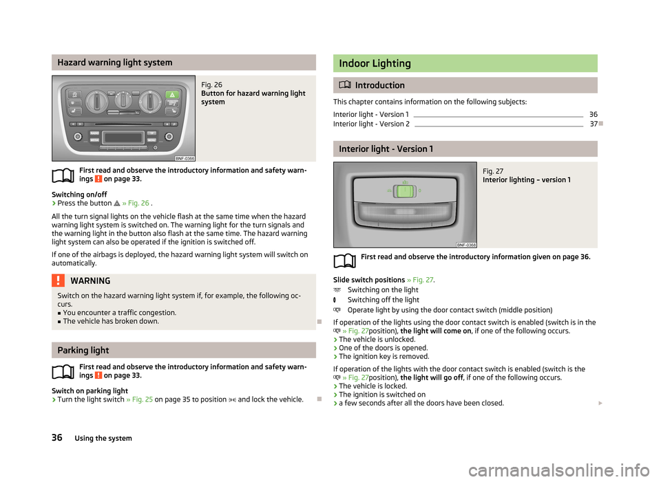
Hazard warning light systemFig. 26
Button for hazard warning light
system
First read and observe the introductory information and safety warn-
ings on page 33.
Switching on/off
›
Press the button
» Fig. 26 .
All the turn signal lights on the vehicle flash at the same time when the hazard
warning light system is switched on. The warning light for the turn signals and
the warning light in the button also flash at the same time. The hazard warning
light system can also be operated if the ignition is switched off.
If one of the airbags is deployed, the hazard warning light system will switch on
automatically.
WARNINGSwitch on the hazard warning light system if, for example, the following oc-
curs.■
You encounter a traffic congestion.
■
The vehicle has broken down.
Parking light
First read and observe the introductory information and safety warn-
ings
on page 33.
Switch on parking light
›
Turn the light switch » Fig. 25 on page 35 to position
and lock the vehicle.
Indoor Lighting
Introduction
This chapter contains information on the following subjects:
Interior light - Version 1
36
Interior light - Version 2
37
Interior light - Version 1
Fig. 27
Interior lighting – version 1
First read and observe the introductory information given on page 36.
Slide switch positions » Fig. 27 .
Switching on the light
Switching off the light
Operate light by using the door contact switch (middle position)
If operation of the lights using the door contact switch is enabled (switch is in the
» Fig. 27 position), the light will come on , if one of the following occurs.
› The vehicle is unlocked.
› One of the doors is opened.
› The ignition key is removed.
If operation of the lights with the door contact switch is enabled (switch is the
» Fig. 27 position), the light will go off , if one of the following occurs.
› The vehicle is locked.
› The ignition is switched on
› a few seconds after all the doors have been closed.
36Using the system
Page 40 of 176
NoteIf the interior light remains switched on when the ignition is switched off or if one
of the doors is open, the light will automatically go out after around 10 minutes.
Interior light - Version 2
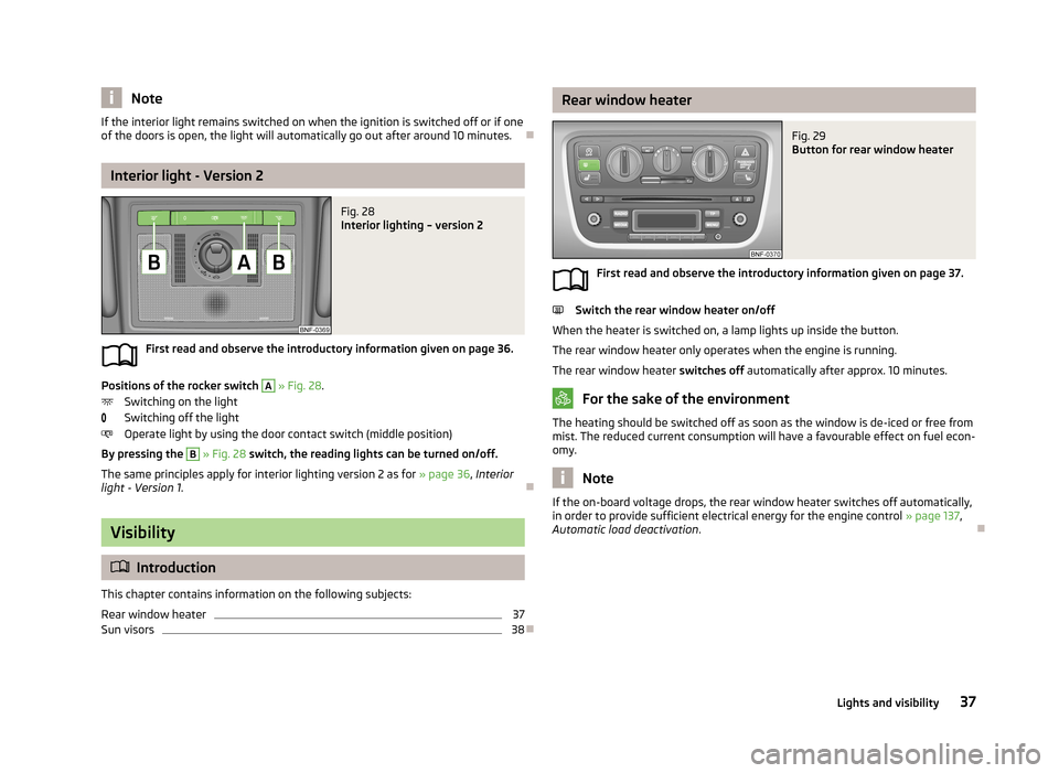
Fig. 28
Interior lighting – version 2
First read and observe the introductory information given on page 36.
Positions of the rocker switch
A
» Fig. 28 .
Switching on the light
Switching off the light
Operate light by using the door contact switch (middle position)
By pressing the
B
» Fig. 28 switch, the reading lights can be turned on/off.
The same principles apply for interior lighting version 2 as for » page 36, Interior
light - Version 1 .
Visibility
Introduction
This chapter contains information on the following subjects:
Rear window heater
37
Sun visors
38
Rear window heaterFig. 29
Button for rear window heater
First read and observe the introductory information given on page 37.
Switch the rear window heater on/off
When the heater is switched on, a lamp lights up inside the button. The rear window heater only operates when the engine is running.
The rear window heater switches off automatically after approx. 10 minutes.
For the sake of the environment
The heating should be switched off as soon as the window is de-iced or free from
mist. The reduced current consumption will have a favourable effect on fuel econ-
omy.
Note
If the on-board voltage drops, the rear window heater switches off automatically,
in order to provide sufficient electrical energy for the engine control » page 137,
Automatic load deactivation .
37Lights and visibility
Page 89 of 176
›The engine has not reached the minimum temperature for the START STOP
mode.
› The temperature inside the vehicle has not reached the desired temperature
set in the air-conditioning system/heating.
› The external temperature is very low/high.
› The windscreen defroster / ventilation is switched on at the maximum air tem-
perature (air conditioning) setting.
› The parking aid is activated.
› The charge state of the vehicle battery is too low.
› The stationary vehicle is on a steep slope or a steep downhill section.
› The idling speed is too high.
› The steering angle is too large (manoeuvring).
The warning symbol
appears in the instrument cluster display.
The automatic start procedure takes place again
During the STOP phase, the engine fires up without any active driver intervention, e.g. in the following situations.
› The vehicle begins to roll, e.g. on a slope.
› The difference between the temperature setting of the air-conditioning sys-
tem/heating and the temperature of the interior is too large.
› The windscreen defroster / ventilation is switched on at the maximum air tem-
perature (air conditioning) setting.
› The brake pedal was pressed several times (the pressure in the braking system
is too low).
› The charge state of the vehicle battery is too low.
› The current consumption is too high.
Manually activating/deactivating the system
Fig. 80
Button for the START-STOP sys-
tem
First read and observe the introductory information and safety warn-
ings on page 85.
Activation/deactivation
›
Press the symbol button » Fig. 80 .
When start-stop mode is deactivated, the warning light in the button lights up.
Note
If the system is deactivated during the STOP phase, the automatic start proce-
dure takes place.
City Safe Drive
Introduction
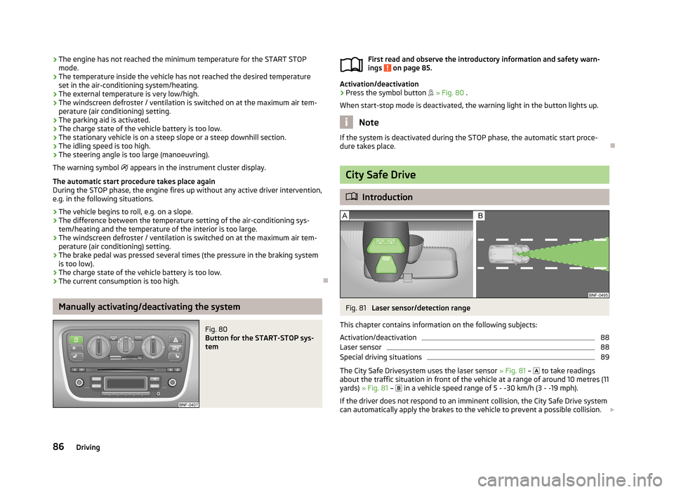
Fig. 81
Laser sensor/detection range
This chapter contains information on the following subjects:
Activation/deactivation
88
Laser sensor
88
Special driving situations
89
The City Safe Drivesystem uses the laser sensor » Fig. 81 –
to take readings
about the traffic situation in front of the vehicle at a range of around 10 metres (11
yards) » Fig. 81 –
in a vehicle speed range of 5 - -30 km/h (3 - -19 mph).
If the driver does not respond to an imminent collision, the City Safe Drive system
can automatically apply the brakes to the vehicle to prevent a possible collision.
86Driving
Page 158 of 176
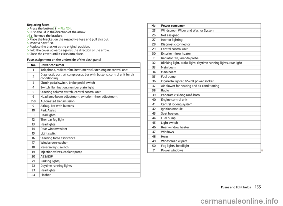
Replacing fuses›Press the button 1 » Fig. 124 .›
Push the lid in the direction of the arrow.
›2
Remove the bracket.
›
Place the bracket on the respective fuse and pull this out.
›
Insert a new fuse.
›
Replace the bracket at the original position.
›
Fold the cover upwards against the direction of the arrow.
›
Close the cover until it clicks into place.
Fuse assignment on the underside of the dash panel
No.Power consumer1Telephone, radiator fan, instrument cluster, engine control unit2Diagnostic port, air compressor, bar with buttons, control unit for air
conditioning3Clutch pedal switch, brake pedal switch4Switch illumination, number plate light5Steering column switch, central control unit6Headlamp beam adjustment, exterior mirror adjustment7-8Automated transmission9Airbag, bar with buttons10Park Assist11Headlights12The rear fog light13Headlights14Rear window wiper15Light switch16Steering force assistance17Windscreen washer18Reverse light switch19Injection valves, coolant pump20ABS/ESP21Parking lights,22Daytime running lights23Headlights24FlasherNo.Power consumer25Windscreen Wiper and Washer System26Not assigned27Interior lighting28Diagnostic connector29Central control unit30Exterior mirror heater31Radiator fan, lambda probe32Blinking light, brake light, daytime running lights, rear light33Main beam34Main beam35Fuel pump36Cigarette lighter, 12-volt power socket37Air blower for heating and air conditioning38Radio39Panoramic sliding roof, horn40Engine control unit41Central locking system42Ignition module43Seat heaters44Fuel pump45Light switch46Rear window heater47Windows48Horn49Windscreen wipers50Fog lights, headlight51Power windows
155Fuses and light bulbs
Page 167 of 176
Index
Numbers and Symbols
12-volt power socket
52
A
Abroad Driving abroad
79
Unleaded petrol79
ABS81
Warning light19
Accessories110
Adjusting Exterior mirrors
41
Interior mirror40
Seat43
Steering wheel66
Adjusting the seats91
Aerial114
Air-conditioning system Air outlet vents
57
Airbag98
Deactivating101
Deactivating the front passenger airbag102
Deployment98
Front airbag99
Modifications and damage to the airbag system112
Side airbag Head-Thorax100
Airbag system98
Air conditioning system59
Control elements60
Recirculated air mode61
Air outlet vents57
Antilock Braking System81
Artificial leather120
Ash tray51
Assist systems80
ABS19, 81
City Safe Drive86
Cruise Control System83
EDS81
ESC18, 80
Parking aid81
START-STOP85
TC81
Traction Control System (TCS)19
Visual parking system82
Automated transmission71
Lever control71
Automatic gearbox Operational faults
73
Tiptronic72
Automatic load deactivation137
Automatic transmission Kick-down
72
Starting-off and driving72
Avoiding damage to the vehicle Driving through water
78
Avoiding damage to your vehicle78
B
Bag hooks
47
Belts94
Belt tensioners97
Bonnet Closing
128
Opening128
Boot Class N1 vehicles
47
Boot lid Automatic locking
29
Brake assist80
Brake booster69
Brake fluid133
Changing134
Checking133
Brakes Brake assist systems80
Brake booster69
Brake fluid133
Handbrake70
Running in74
Warning lights16
Braking Information on braking
69
Breakdown kit149
Bulbs In the tail light
159
Replacing157
Button in the driver's door Electrical power windows
30
C
Car computer see multifunction display
13
Carrier49
Cavity protection117
Central locking button27
Central locking system25
lock26
unlock26
Changing Brake fluid
134
Engine oil131
Fuses on the underside of the dash panel154
Wheels145
Changing a wheel Follow-up work
146
Preliminary work145
Remove and attaching a wheel146
Charging a vehicle battery136
Checking Battery electrolyte level
135
Brake fluid133
Coolant132
Engine oil131
164Index