change wheel SKODA CITIGO 2014 1.G User Guide
[x] Cancel search | Manufacturer: SKODA, Model Year: 2014, Model line: CITIGO, Model: SKODA CITIGO 2014 1.GPages: 164, PDF Size: 12.08 MB
Page 127 of 164
›The temporary spare wheel is inflated to the maximum inflation pressure for
the vehicle » page 118.
› Only use this temporary spare wheel to reach the nearest specialist garage,
since it is not intended for permanent use.WARNING■ Never drive with more than one temporary spare wheel mounted!■Only use the temporary spare wheel when absolutely necessary.■
Avoid accelerating at full throttle, sharp braking and fast cornering.
■
The snow chains cannot be used on the temporary spare wheel.
■
Observe the instructions on the warning sign of the temporary spare
wheel.
Changing a wheel
Introduction
This chapter contains information on the following subjects:
Preliminary work
124
Full wheel trim
124
Wheel bolts
125
Changing a wheel
125
Follow-up work
125
Loosening/tightening wheel bolts
126
Raising the vehicle
126
Anti-theft wheel bolts
127
For your own safety and the safety of the passengers, the following instruc-
tions must be observed before changing a wheel on the road.
Switch on the hazard warning lights system.
The warning triangle must be set up at the prescribed distance - observe
the national legal provisions when doing so.
Park the vehicle as far away as possible from the flow of traffic.
Choose a location with a flat, solid surface.
Have all the occupants get out. The passengers should not stand on the
road (instead they should remain behind a crash barrier, for instance) while
the wheel is being changed.
The following instructions must be followed if the vehicle is subsequently fit-
ted with tyres or rims that differ from the factory-fitted ones » page 120, Ex-
planation of the tyre labelling .
The national legal requirements must be observed when changing a wheel.
Preliminary work
Before changing the wheel, the following work must be carried out.
›
Switch off the engine.
›
Select first gear or place the selector lever for automatic gearbox in the D or
R position .
›
Firmly apply the handbrake.
›
Remove the vehicle tool kit » page 122 and the spare wheel » page 123 from
the boot.
Full wheel trim
Before removing the wheel bolts, remove the wheel cover.
Pulling off
›
Hook the clamp found in the vehicle tool kit » page 122 into the reinforced
edge of the wheel trim.
›
Push the wheel wrench through the clamp, support on the tyre and pull off
the wheel trim.
Installing
›
Press the wheel trim onto the wheel rim at the designated valve open-
ing » .
›
Then press the trim into the wheel rim until its entire circumference locks
correctly in place.
CAUTION
■ Use the pressure of your hand only, do not strike the full wheel trim. The
cover could be damaged.■
When using the anti-theft wheel bolt, ensure that it is in the hole in the
valve area.
■
If wheel trims are fitted, an adequate flow of air must be assured in order to
cool the brake system.
Note
We recommend that you use wheel trims from ŠKODA Original Accessories.124Do-it-yourself
Page 130 of 164
WARNINGNotes for vehicle lifting■Choose a flat and firm surface for jacking the vehicle.■
If the wheel has to be changed on a slope, first of all block the opposite
wheel with a stone or similar object to prevent the vehicle from unexpect-
edly rolling away.
■
Secure the base plate of the lifting jack with suitable means to prevent
possible moving. A soft and slippery ground under the base plate may move
the lifting jack, causing the vehicle to fall down. It is therefore always nec-
essary to place the lifting jack on a solid surface or use a wide and stable
base. Use a non-slip base (e.g. a rubber foot mat) if the surface is smooth,
such as cobbled stones, tiled floor, etc.
■
Only attach the lifting jack to the attachment points provided for this pur-
pose.
■
Always raise the vehicle with the doors closed.
■
Never position any body parts, such as arms or legs under the vehicle,
while the vehicle is raised with a lifting jack.
■
When the vehicle is raised, never start the engine.
CAUTION
It is important to ensure that the jack is correctly attached to the web of the
lower fork leg - risk of damage to the vehicle.
Anti-theft wheel bolts
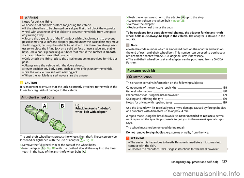
Fig. 113
Principle sketch: Anti-theft
wheel bolt with adapter
The anti-theft wheel bolts protect the wheels from theft. These can only be
loosened or tightened with the use of adapter
B
» Fig. 113 .
›
Remove the full wheel trim or the caps of the wheel bolts.
›
Insert adapter
B
» Fig. 113 with the toothed side all the way into the inner
teeth in the head of the anti-theft wheel bolts
A
.
› Push the wheel wrench onto the adapter B up to the stop.›Loosen or tighten the wheel bolt
» page 126.›
Remove the adapter.
›
Replace the wheel trim or the caps.
To be equipped for a possible wheel change, the adapter for the anti-theft
wheel bolts must always be kept in the vehicle. The adapter is stowed in the
tool kit.
Note
■ Note the code number which is embossed both on the adapter and also on
the end of each anti-theft wheel bolt. This number can be used to purchase a
replacement adapter from ŠKODA Original Parts if necessary.■
The anti-theft wheel bolt set and adapter can be purchased from a ŠKODA
Partner.
Puncture repair kit
Introduction
This chapter contains information on the following subjects:
Components of the puncture repair kits
128
General information
128
Preparations for using the breakdown kit
129
Sealing and inflating the tyre
129
Notes for driving with repaired tyres
129
Use the breakdown kit to reliably repair tyre damage caused by foreign bodies
or a puncture with diameters up to approx. 4 mm.
A repair made using the breakdown kit is never intended to replace a perma-
nent repair on the tyre. Its purpose is to get you to the nearest specialist ga-
rage.
The wheel must not be removed during repair.
Do not remove foreign bodies , e.g. screws or nails, from the tyre.
WARNING■
The sealant is hazardous to heath. Remove immediately if it comes into
contact with the skin.■
Observe the manufacturer's usage instructions for the breakdown kit.
127Emergency equipment and self-help
Page 131 of 164
For the sake of the environmentUsed sealant or sealant whose expiry date has passed must be disposed of in
accordance with environmental protection regulations.
Note
■ A new bottle of sealant can be purchased from ŠKODA Original Parts.■Immediately replace the tyre that was repaired using the breakdown kit, or
consult a specialist garage about repair options.
Components of the puncture repair kits
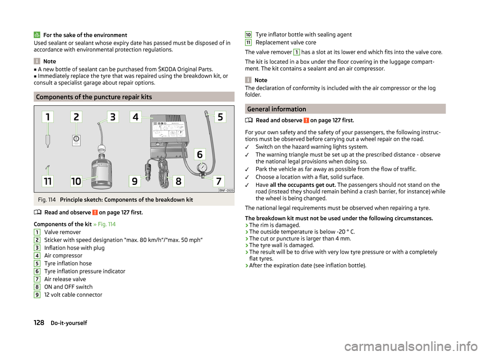
Fig. 114
Principle sketch: Components of the breakdown kit
Read and observe
on page 127 first.
Components of the kit » Fig. 114
Valve remover
Sticker with speed designation “max. 80 km/h”/“max. 50 mph” Inflation hose with plug
Air compressor
Tyre inflation hose
Tyre inflation pressure indicator
Air release valve
ON and OFF switch
12 volt cable connector
123456789Tyre inflator bottle with sealing agent
Replacement valve core
The valve remover 1
has a slot at its lower end which fits into the valve core.
The kit is located in a box under the floor covering in the luggage compart-
ment. The kit contains a sealant and an air compressor.
Note
The declaration of conformity is included with the air compressor or the log
folder.
General information
Read and observe
on page 127 first.
For your own safety and the safety of your passengers, the following instruc-
tions must be observed before carrying out a wheel repair on the road.
Switch on the hazard warning lights system.
The warning triangle must be set up at the prescribed distance - observe
the national legal provisions when doing so.
Park the vehicle as far away as possible from the flow of traffic.
Choose a location with a flat, solid surface.
Have all the occupants get out. The passengers should not stand on the
road (instead they should remain behind a crash barrier, for instance) while
the wheel is being changed.
The national legal requirements must be observed when repairing a tyre.
The breakdown kit must not be used under the following circumstances. › The rim is damaged.
› The outside temperature is below -20 ° C.
› The cut or puncture is larger than 4 mm.
› The tyre wall is damaged.
› The result will be to drive with very low tyre pressure or with a completely
flat tyres.
› After the expiration date (see inflation bottle).
1011128Do-it-yourself
Page 141 of 164
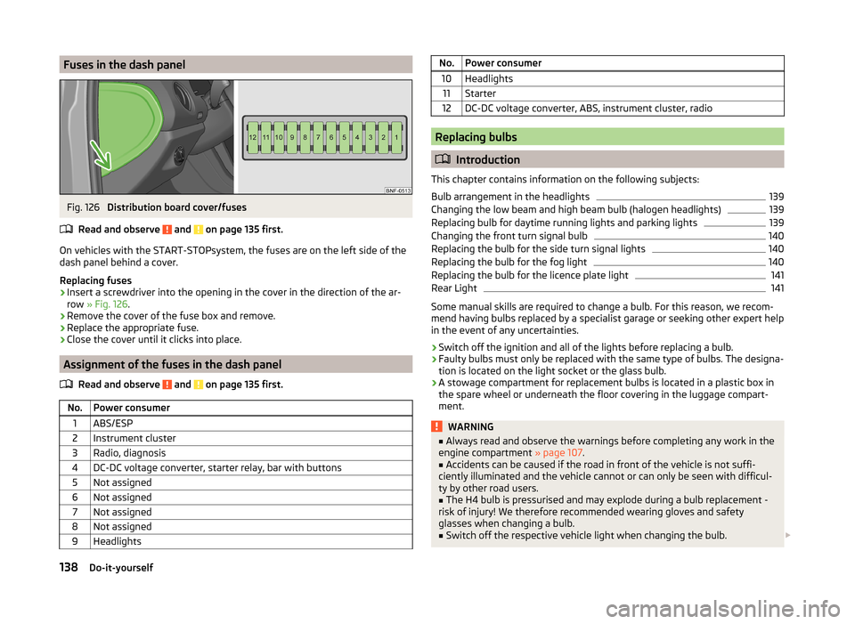
Fuses in the dash panelFig. 126
Distribution board cover/fuses
Read and observe
and on page 135 first.
On vehicles with the START-STOPsystem, the fuses are on the left side of the
dash panel behind a cover.
Replacing fuses
›
Insert a screwdriver into the opening in the cover in the direction of the ar-
row » Fig. 126 .
›
Remove the cover of the fuse box and remove.
›
Replace the appropriate fuse.
›
Close the cover until it clicks into place.
Assignment of the fuses in the dash panel
Read and observe
and on page 135 first.
No.Power consumer1ABS/ESP2Instrument cluster3Radio, diagnosis4DC-DC voltage converter, starter relay, bar with buttons5Not assigned6Not assigned7Not assigned8Not assigned9HeadlightsNo.Power consumer10Headlights11Starter12DC-DC voltage converter, ABS, instrument cluster, radio
Replacing bulbs
Introduction
This chapter contains information on the following subjects:
Bulb arrangement in the headlights
139
Changing the low beam and high beam bulb (halogen headlights)
139
Replacing bulb for daytime running lights and parking lights
139
Changing the front turn signal bulb
140
Replacing the bulb for the side turn signal lights
140
Replacing the bulb for the fog light
140
Replacing the bulb for the licence plate light
141
Rear Light
141
Some manual skills are required to change a bulb. For this reason, we recom-
mend having bulbs replaced by a specialist garage or seeking other expert help
in the event of any uncertainties.
› Switch off the ignition and all of the lights before replacing a bulb.
› Faulty bulbs must only be replaced with the same type of bulbs. The designa-
tion is located on the light socket or the glass bulb.
› A stowage compartment for replacement bulbs is located in a plastic box in
the spare wheel or underneath the floor covering in the luggage compart-
ment.
WARNING■ Always read and observe the warnings before completing any work in the
engine compartment » page 107.■
Accidents can be caused if the road in front of the vehicle is not suffi-
ciently illuminated and the vehicle cannot or can only be seen with difficul-
ty by other road users.
■
The H4 bulb is pressurised and may explode during a bulb replacement -
risk of injury! We therefore recommended wearing gloves and safety
glasses when changing a bulb.
■
Switch off the respective vehicle light when changing the bulb.
138Do-it-yourself
Page 152 of 164
Cavity protection100
Central locking39
Central locking button43
Change engine oil
110
Change engine oil
110
Changing Front turn signal bulb
140
Fuses on the underside of the dash panel136
light bulb in tail light141
Low beam and high beam bulb - halogen head- lights
139
Wheels124
Changing a wheel Follow-up work
125
Preliminary work124
Remove and attaching a wheel125
Charging a vehicle battery115
Checking Battery electrolyte level
115
Brake fluid113
Coolant112
Engine oil110
Oil level110
Windscreen washer fluid109
Checks Statutory checks
93
Children and safety19
Child safety Side airbag
21
Child safety lock43
Child seat Classification
22
ISOFIX22
on the front passenger seat20
TOP TETHER23
Use of child seats22
Use of ISOFIX child seats23
Chrome parts see vehicle care99
Cigarette lighter61
City Safe Drive90
Disable/Enable91
Operation90
warning symbol39
cleaning chrome parts
99
Cleaning Alcantara
102
and maintaining belts103
artificial leather102
headlight glasses99
materials102
natural leather101
plastic parts98
seats covers of the electrically heated seats102
wheels100
Cleaning safety belt
103
Cleaning seat covers
102
Cleaning the interior artificial leather
102
Seat covers102
Cleaning the outside of the vehicle Decorative films
99
Cleaning the vehicle exterior Cavity protection
100
Door locking cylinder100
Headlight glasses99
Under-body protection100
wheels100
Windows and external mirrors99
Cleaning vehicle96
Cleaning vehicle exterior97
Plastic parts98
Rubber seals98
Vehicle paint work98
Wiper blades101
Clean interior Safety belt
103
clean outside of vehicle chrome parts
99
Clothes hook64
CNG106
Fuel reserve display29
refuelling105
Refuelling105
Sticker106
Cockpit 12-Volt power outlet
62
Ashtray62
Cigarette lighter61
General view27
Light51
storage compartments60
useful equipment60
compartments60
Components of the puncture repair kits128
Compressed natural gas see CNG
106
Computer see multi-function display
30
convenience turn signal50
Coolant111
Checking112
Replenishing112
Warning light35
Cooling system cost-effective use
72
malfunctions72
Correct seated position9
Driver9
Front passenger10
Instructions11
Rear seats10
Counter for distance driven30
149Index
Page 156 of 164
Puncture repair kit127
R
Radiator fan
109
Radio4
Raising the vehicle126
Rear-view mirror Exterior mirrors
54
Rear fog light50
Warning light37
Rear mirror54
Interior mirror54
Rear window heating52
Rear windows Closing
45
Opening45
Recirculation72
Refuelling104
Fuel104
Fuel - natural gas105
Regulation Lighting range
48
Remote control Locking
41
Replacing the battery133
Synchronisation process133
Unlocking41
Remote control key Replacing the battery
133
Repairs and technical alterations93
Replace vehicle battery
116
Replace vehicle battery
116
Replacing Bulb for daytime running lights and parkinglights
139
Bulb for the fog light140
Bulb for the licence plate light141
Bulb for the side turn signal lights140
Bulbs138
Fuses135
Fuses in the dash panel138
Fuses in the engine compartment137
window wiper blade135
windscreen wiper blades134
Replenishing Coolant
112
Engine oil111
Windscreen washer fluid109
Roof Load
69
Roof rack68
mounting points69
Roof load69
Rubber seals98
Running in and economical driving82
S
SAFE See Safe securing system
42
SAFELOCK See Safe securing system
42
Safe securing system42
Safety8
Child safety19
Child safety seats19
Correct seated position9
Head restraints56
ISOFIX22
TOP TETHER23
Safety belt Warning symbol
38
Save electrical energy82
Save fuel82
Seals Vehicle care
98
Seat Adjusting
56
Seat belts11
Belt tensioners14
fastening and unfastening13
Inertia reels14
The physical principle of a frontal collision13
Warning light34
Seat features57
Seats Folding front passenger seat
58
Head restraints56
Heating57
Seat backrests59
Seats and head restraint55
Service94
Service display30
Setting33
seats and head restraints55
Setting the33
Shift Gear recommendation
30
Information on the gear changed30
Side airbag17
Sidelights48
Sliding/tilting roof Closing
46
Opening and tilting46
Operation46
Snow chains121
spare123
spare wheel123
instructions123
Spare wheel Change
123
Speedometer28
Speed symbol See Wheels
120
Spoiler95
Staring engine Jump-starting
130
153Index