key SKODA CITIGO 2014 1.G User Guide
[x] Cancel search | Manufacturer: SKODA, Model Year: 2014, Model line: CITIGO, Model: SKODA CITIGO 2014 1.GPages: 164, PDF Size: 12.08 MB
Page 52 of 164
We recommend you adjust the headlight beam when the low beam is switched
on.WARNINGAlways adjust the headlight beam to meet the following conditions.■The vehicle does not dazzle other road users, especially oncoming vehi-
cles.■
The beam range is sufficient for safe driving.
CAUTION
If leaving the vehicle without wanting to use the parking lights, always turn
the light switch to position .
Note
If the light switch is in the position , the ignition key is removed and the
driver's door is open, an audible warning signal will sound. The audible warning
signal is switched off by means of the door contact when the driver's door is
closed, however the side lights remain on to illuminate the parked vehicle if
necessary.
Daylight running lights (DAY LIGHT)
Read and observe
on page 48 first.
The daytime running lights function provides the lighting of the front area ofthe vehicle.
The daytime running lights are switched on automatically if the following
conditions are met.
The ignition is switched on.
The light switch is in position
» Fig. 35 on page 48 .
When the daytime running lights are switched on, the lighting of the instru-
ment cluster is switched on.
WARNINGWhen the daytime running light is switched on, the side lights (neither at
the front or rear) and the number plate lights are not illuminated. Therefore
always switch on the low beam when the visibility is poor.Turn signal and main beamFig. 36
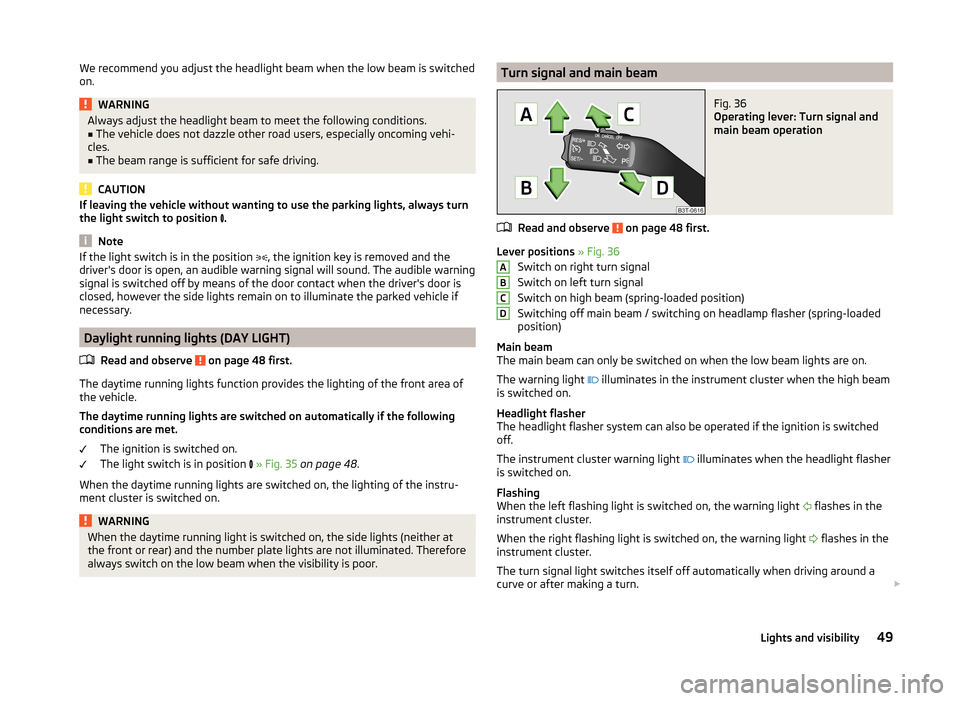
Operating lever: Turn signal and
main beam operation
Read and observe on page 48 first.
Lever positions » Fig. 36
Switch on right turn signal
Switch on left turn signal
Switch on high beam (spring-loaded position)
Switching off main beam / switching on headlamp flasher (spring-loaded
position)
Main beam
The main beam can only be switched on when the low beam lights are on.
The warning light illuminates in the instrument cluster when the high beam
is switched on.
Headlight flasher
The headlight flasher system can also be operated if the ignition is switched
off.
The instrument cluster warning light illuminates when the headlight flasher
is switched on.
Flashing
When the left flashing light is switched on, the warning light flashes in the
instrument cluster.
When the right flashing light is switched on, the warning light flashes in the
instrument cluster.
The turn signal light switches itself off automatically when driving around a
curve or after making a turn.
ABCD49Lights and visibility
Page 53 of 164
“Convenience turn signal”
If you only wish to flash three times, briefly push the lever to the upper or low-
er pressure point and release again.WARNINGOnly turn on the main beam or the headlight flasher if other road users will
not be dazzled.
Note
An acoustic warning signal will sound when the driver's door is opened if the
lever is not in the middle position after removing the ignition key from the igni-
tion lock. The acoustic warning signal will stop just as soon as the driver's door
is closed.
Fog lights
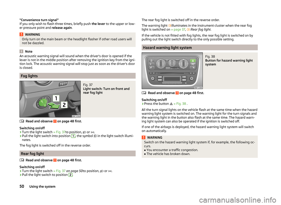
Fig. 37
Light switch: Turn on front and
rear fog light
Read and observe on page 48 first.
Switching on/off
›
Turn the light switch » Fig. 37to position,
or
.
›
Pull the light switch into position
1
, the symbol
in the light switch illumi-
nates.
The fog light is switched off in the reverse order.
Rear fog light
Read and observe
on page 48 first.
Switching on/off
›
Turn the light switch » Fig. 37 on page 50 to position,
or
.
›
Pull the light switch to position
2
.
The rear fog light is switched off in the reverse order.
The warning light
illuminates in the instrument cluster when the rear fog
light is switched on » page 37,
Rear fog light .
If the vehicle is not fitted with fog lights, the rear fog light is switched on by
pulling out the light switch directly to the only possible setting.
Hazard warning light system
Fig. 38
Button for hazard warning light
system
Read and observe on page 48 first.
Switching on/off
›
Press the button
» Fig. 38 .
All the turn signal lights on the vehicle flash at the same time when the hazard
warning light system is switched on. The warning light for the turn signals and
the warning light in the button also flash at the same time. The hazard warn-
ing light system can also be operated if the ignition is switched off.
If one of the airbags is deployed, the hazard warning light system will switch
on automatically.
WARNINGSwitch on the hazard warning light system if, for example, the following oc-
curs.■
You encounter a traffic congestion.
■
The vehicle has broken down.
50Using the system
Page 54 of 164
Parking lightRead and observe
on page 48 first.
Switching on the side light on one side
›
Switch off the ignition.
›
Place the control lever into position
A
or
B
as far as it can go » Fig. 36 on
page 49 - the parking light on the right/left-hand side of the vehicle is
switched on.
Switching on the side light on both sides
›
Turn the light switch
» Fig. 37 on page 50 to position
and lock the vehicle.
After pulling out the ignition key and opening the driver's door, an audible
warning sounds. After a few seconds or after closing the driver's door, the au-
dible alarm is turned off, but the parking lights will remain switched on.
CAUTION
Turning on the parking light means the battery is heavily loaded, especially
over short distances.
Driving abroad
Read and observe
on page 48 first.
The low beam is set asymmetrically. It illuminates the side of the road on
which the vehicle is being driven to a greater extent.
When driving in countries with opposing traffic system (traffic on the left/
right), asymmetric headlight adjustment can dazzle oncoming traffic. In order
to avoid this, the headlights must be adjusted at a specialist garage.
Note
You can find out more information on adjusting the headlights at a specialist
garage.
Indoor Lighting
Introduction
This chapter contains information on the following subjects:
Interior light
51NoteWith the ignition off, the light turns off automatically after about 10 minutes.
Interior light
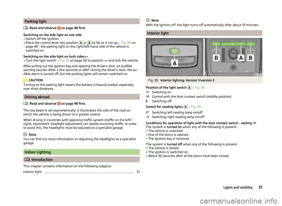
Fig. 39
Interior lighting: Version 1/version 2
Position of the light switch
A
» Fig. 39
Switching on
Control with the door contact switch (middle position)
Switching off
Switch for reading lights
B
» Fig. 39
Switching left reading lamp on/off
Switching right reading lamp on/off
Conditions for operation of light with the door contact switch - setting
The system is turned on when any of the following is present.
› The vehicle is unlocked.
› One of the doors is opened.
› The ignition key is removed.
The system is turned off when any of the following is present.
› The vehicle is locked.
› The ignition is switched on.
› About 30 seconds after all the doors have been closed.
51Lights and visibility
Page 60 of 164
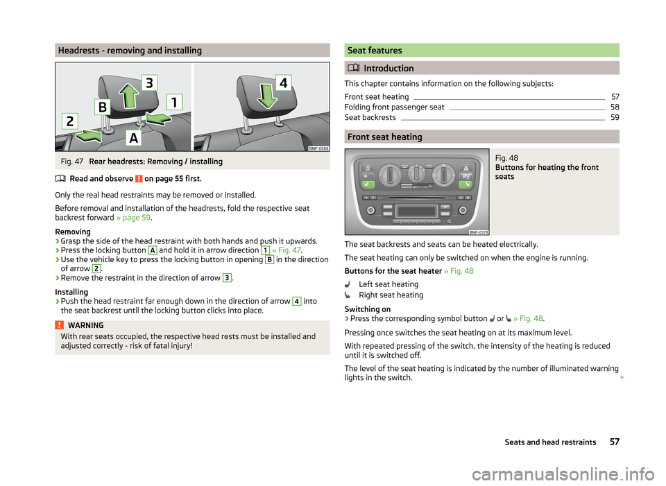
Headrests - removing and installingFig. 47
Rear headrests: Removing / installing
Read and observe
on page 55 first.
Only the real head restraints may be removed or installed.
Before removal and installation of the headrests, fold the respective seat
backrest forward » page 59.
Removing
›
Grasp the side of the head restraint with both hands and push it upwards.
›
Press the locking button
A
and hold it in arrow direction
1
» Fig. 47 .
›
Use the vehicle key to press the locking button in opening
B
in the direction
of arrow
2
.
›
Remove the restraint in the direction of arrow
3
.
Installing
›
Push the head restraint far enough down in the direction of arrow
4
into
the seat backrest until the locking button clicks into place.
WARNINGWith rear seats occupied, the respective head rests must be installed and
adjusted correctly - risk of fatal injury!Seat features
Introduction
This chapter contains information on the following subjects:
Front seat heating
57
Folding front passenger seat
58
Seat backrests
59
Front seat heating
Fig. 48
Buttons for heating the front
seats
The seat backrests and seats can be heated electrically.
The seat heating can only be switched on when the engine is running.
Buttons for the seat heater » Fig. 48
Left seat heating
Right seat heating
Switching on
›
Press the corresponding symbol button or
» Fig. 48 .
Pressing once switches the seat heating on at its maximum level.
With repeated pressing of the switch, the intensity of the heating is reduced
until it is switched off.
The level of the seat heating is indicated by the number of illuminated warning
lights in the switch.
57Seats and head restraints
Page 79 of 164
Driving
Starting-off and Driving
Starting and turning off the engine
Introduction
This chapter contains information on the following subjects:
Electronic immobilizer
76
Lock/unlock steering lock
76
Ignition on / off and start the engine
77
Switch off engine
77
With the key in the ignition, the ignition can be switched on and off and the
engine can be started / stopped.
WARNING■ While driving with the engine stopped, the ignition must always be
switched on » page 77, Ignition on / off and start the engine .
■ With the ignition off, the steering may lock » page 76 - danger of an
accident!■
Do not withdraw the ignition key from the ignition lock until the vehicle
has come to a stop » page 79, Parking . Otherwise, the steering could be
blocked – risk of accident!
■
Never leave the key in the vehicle when you exit the vehicle. Unauthor-
ized persons, such as children, for example, could lock the car, turn on the
ignition or start the engine - there is a danger of injury, accidents and dam-
age!
■
Never leave the vehicle unattended with the engine running - there is
risk of accident, damage or theft!
■
Never switch off the engine before the vehicle is stationary – risk of acci-
dent!
WARNING■ Never (e.g. in garages) run the engine in a closed place - there is the dan-
ger of poisoning and death!■
Do not leave any items (e.g. cloths or tools) in the engine compartment.
This presents a fire hazard and the risk of engine damage.
■
Never cover the engine with additional insulation material (e.g. with a
cover) – risk of fire!
CAUTION
■ Only start the engine when the engine and the vehicle are stationary - there
is a danger of starter and engine damage!■
Do not push-start the engine – risk of damaging the engine and the catalytic
converter. The battery from another vehicle can be used as a jump-start
aid » page 130 .
Note
Do not warm up the engine while the vehicle is stationary. If possible, start
your journey as soon as the engine has started. Through this, the engine rea-
ches its operating temperature faster.
Electronic immobilizer
Read and observe
and on page 76 first.
The electronic immobilizer makes a possible attempted theft or unauthorizeduse of your vehicle more difficult.
An electronic chip is integrated in the head of the key. The immobiliser is deac-
tivated with the aid of this chip when the key is inserted in the ignition lock.
The electronic immobiliser is automatically activated when the ignition key is
withdrawn from the lock.
The engine will not start if a non-authorized ignition key is used.
Lock/unlock steering lock
Read and observe
and on page 76 first.
The steering lock (steering lock) deters any attempted theft of your vehicle.
Locking
›
Withdraw the ignition key.
76Driving
Page 80 of 164
›Turn the steering wheel to the left or right until the steering lock clicks into
place.
Unlocking›
Insert the key into the ignition lock.
›
Switch on the ignition » page 77.
The steering lock is unlocked.
If the ignition switch can not be turned on, then turn the steering wheel back and forth slightly and thereby unlock the steering lock.
Ignition on / off and start the engine
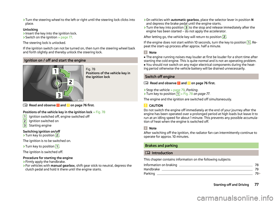
Fig. 78
Positions of the vehicle key in
the ignition lock
Read and observe and on page 76 first.
Positions of the vehicle key in the ignition lock » Fig. 78
Ignition switched off, engine switched off
Ignition switched on
Starting engine
Switching ignition on/off
›
Turn key to position
2
.
The ignition is to be switched on.
›
Turn key to position
1
.
The ignition is switched off.
Procedure for starting the engine
›
Firmly apply the handbrake.
›
For vehicles with manual gearbox, shift gear stick to neutral, depress the
clutch pedal and hold it there until the engine starts.
123› On vehicles with
automatic gearbox , place the selector lever in position N
and depress the brake pedal until the engine starts.›
Turn the key into position
3
to the stop and release immediately after the
engine has been started – do not apply the accelerator.
After letting go, the vehicle key will return to position
2
.
If the engine does not start within 10 seconds, turn the key to position
1
. Re-
peat the start-up process after approx. half a minute.
Note
■ The engine running noises may louder at first be louder for a short time after
starting the cold engine. This is quite normal and is not an operating problem.■
You should not switch on any major electrical components during the heat-
ing period otherwise the vehicle battery will be drained unnecessarily.
Switch off engine
Read and observe
and on page 76 first.
›
Stop the vehicle » page 79, Parking .
›
Turn key to position
1
» Fig. 78 on page 77 .
The engine and the ignition are switched off simultaneously.
CAUTION
Do not switch the engine off immediately at the end of your journey after the
engine has been operated over a prolonged period at high loads but leave it to
run at an idling speed for about 1 minute. This prevents any possible accumula-
tion of heat when the engine is switched off.
Note
After switching off the ignition, the radiator fan can intermittently continue to
operate for approx. 10 minutes.
Brakes and parking
Introduction
This chapter contains information on the following subjects:
Information on braking
78
Handbrake
79
Parking
79
77Starting-off and Driving
Page 95 of 164
WARNING (Continued)■If the laser sensor is damaged or faulty.■When the vehicle is on a rolling test bench.■
When the windscreen is damaged in the region of the laser sensor.
■
For example, if the charge extends to the roof rack over the front edge of
the roof.
Tyre pressure monitoring
Introduction
This chapter contains information on the following subjects:
Save tyre pressure values
92
The tyre pressure monitoring function (hereinafter referred to only as a sys-
tem) monitors the tyre pressure while driving.
If the rolling circumference of a wheel is changed, the warning light in the
instrument cluster illuminates and an audible signal sounds.
Information on the procedure for the notification of change of tyre inflation
pressure » page 37 .
The system can only function properly if the tyres have the prescribed inflation
pressure and these pressure values are stored in the system.
WARNING■ Having the correct tyre inflation pressure is always the driver's responsi-
bility. Tyre pressure should be checked regularly » page 118.■
The system cannot warn in case of very rapid tyre inflation pressure loss,
e.g. in case of sudden tyre damage.
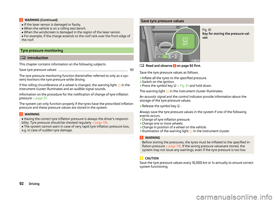
Save tyre pressure valuesFig. 91
Key for storing the pressure val-
ues
Read and observe on page 92 first.
Save the tyre pressure values as follows.
›
Inflate all the tyres to the specified pressure.
›
Switch on the ignition.
›
Press the symbol key
» Fig. 91 and hold down.
The warning light in the instrument cluster illuminates.
An acoustic signal and the control indicator provide information about the
storage of the tyre pressure values.
›
Release the symbol key .
Always save the tyre pressure values in the system if one of the following
events occurs.
› Change of tyre inflation pressure.
› Change one or more wheels.
› Change in position of a wheel on the vehicle.
› Illumination of the warning light
in the instrument cluster.
WARNINGBefore storing the pressures, the tyres must be inflated to the specified in-
flation pressure » page 118. If the wrong pressure valuesare stored, the
system may not issue any warnings, even if the tyre pressure is too low.
CAUTION
Save the tyre pressure values every 10,000 km or 1x annually to ensure correct
system functioning.92Driving
Page 107 of 164
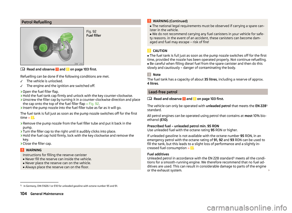
Petrol RefuellingFig. 92
Fuel filler
Read and observe and on page 103 first.
Refuelling can be done if the following conditions are met.The vehicle is unlocked.
The engine and the ignition are switched off.
›
Open the fuel filler flap.
›
Hold the fuel tank cap firmly and unlock with the key counter-clockwise.
›
Unscrew the filler cap by turning it in a counter-clockwise direction and place
the cap onto the top of the fuel filler flap » Fig. 92.
›
Insert the pump nozzle into the fuel filler tube as far as it will go.
The fuel tank is full just as soon as the pump nozzle switches off for the first
time »
.
›
Remove the pump nozzle from the fuel filler tube and put it back in the
pump.
›
Turn the filler cap to the right until it audibly clicks into place.
›
Hold the fuel cap hold firmly, lock with the key clockwise and remove the
key.
›
Close the filler cap.
WARNINGInstructions for filling the reserve canister■Never fill the reserve can inside the vehicle.■
Never place the reserve can on the vehicle.
■
Always place the reserve can on the floor.
WARNING (Continued)■ The national legal requirements must be observed if carrying a spare can-
ister in the vehicle.■
We do not recommend carrying any fuel canisters in your vehicle for safe-
ty reasons. in the event of an accident, these canisters can become dam-
aged and fuel may escape – risk of fire!
CAUTION
■ The fuel tank is full just as soon as the pump nozzle switches off for the first
time, provided the nozzle has been operated properly. Not continue refuelling.■
Be careful when filling diesel fuel from the spare canister and then do this
slowly and cautiously – danger of contaminating the body.
Note
The fuel tank has a capacity of about 35 litres, including a reserve of approx.
4 litres .
Lead-free petrol
Read and observe
and on page 103 first.
The vehicle can only be operated with unleaded petrol that meets the EN 2281)
standard.
All petrol engines can be operated using petrol that contains at most 10% bio-
ethanol (E10).
Prescribed fuel – unleaded petrol min. 95 RON
Use unleaded fuel with the octane rating 95 RON or higher.
If unleaded gasoline is not available with the octane number 95 RON, in an
emergency petrol with the octane rating of 91, 92 and 93 RON can be used to
fill the tank, but this leads to a slight loss of performance and a slightly in-
creased fuel consumption »
.
Fuel additives
Unleaded petrol in accordance with the EN 228 standard 1)
meets all the condi-
tions for a smooth-running engine. We therefore recommend that no fuel ad-
ditives are used. This can result in considerable damage to parts of the engine
or the exhaust system.
1)
In Germany, DIN 51626-1 or E10 for unleaded gasoline with octane number 95 and 91.
104General Maintenance
Page 110 of 164
Automatically switching over from natural gas mode to petrol mode
The vehicle automatically switches from natural gas to petrol, for example, if one of the following cases occurs.
› With an empty gas tank or not enough pressure in the tank.
› After refuelling with natural gas.
› At very low surrounding temperatures.
Gas smell
If you smell gas proceed as follows.
› Stop the vehicle.
› Put out cigarettes.
› Switch off the ignition.
› Open doors and the boot lid to ventilate the vehicle sufficiently.
› Remove any spark producing or incendiary items from the car and immedi-
ately switch off.
› Do not continue if the odour persists.
Seek help from a specialist garage to correct the gas system fault.
Regular gas system checks must be carried out in a specialist workshop on
natural gas-powered vehicles.WARNINGWhen operating a CNG-powered vehicle, the national legal requirements
must be observed.WARNINGDo not underestimate the smell of gas in the car or when refuelling - it may
result in fire, explosion and injury.
Engine compartment
Introduction
This chapter contains information on the following subjects:
Opening and closing the bonnet
108
Engine compartment overview
109
Radiator fan
109
Windscreen washer system
109WARNINGInjuries or scolding or risks of accident or fire may occur when working in
the engine compartment. For this reason, it is essential to comply with the
warning instructions outlined below and with the general applicable safety
rules. The engine compartment of your car is a hazardous area!WARNINGInstructions before beginning work in the engine compartment■Turn off the engine and withdraw the ignition key.■
Firmly apply the handbrake.
■
For vehicles with manual transmission the lever into the neutral position.
■
For vehicles with automated manual transmission, shift the lever to posi-
tion N.
■
Allow the engine to cool.
■
Never open the bonnet if you can see steam or coolant escaping from the
engine compartment – risk of scalding! Wait until no more steam or coolant
is escaping.
WARNINGInformation for working in the engine compartment■Keep all people, especially children, away from the engine compartment.■
Never touch the radiator fan while the engine is still warm. The fan might
suddenly start running!
■
Do not touch any hot engine parts – risk of burns!
WARNINGInformation for working in the engine compartment with the engine run-
ning■
Pay particular attention to moving engine parts, e.g. V-ribbed belt, gener-
ator, radiator fan - danger to life!
■
Never touch the electric wiring on the ignition system.
■
Avoid short circuits in the electrical system – particularly on the vehicle's
battery.
■
Always make sure that no jewellery, loose clothing or long hair can get
caught in rotating engine parts – risk to life! Always remove any jewellery,
tie back long hair and wear tight fitting clothing before completing any
work.
107Inspecting and replenishing
Page 135 of 164
Please note that the brake servo unit and power steering only operate if the
engine is running. If the engine is not running, significantly more physical force
is required to depress the brake pedal and steer the vehicle.
If using a tow rope, ensure that it is always kept taught.
Both drivers should be familiar with the problems which might occur while a vehicle is being towed. Unskilled drivers should not attempt to tow in another
vehicle or to be towed in.
The vehicle must be transported on a special breakdown vehicle or trailer if it
is not possible to tow in the vehicle in the way described or if the towing dis-
tance is greater than 50 km.WARNING■ When towing, respect the national legal provisions, especially those
which relate to the identification of the towing vehicle and the vehicle be-
ing towed.■
When towing, exercise increased caution.
■
Do not use spiral rope for towing » Fig. 117-
, the towing eye may un-
screw from the vehicle - risk of accident.
■
Ensure tow rope is not twisted - risk of accident.
CAUTION
■ Do not tow start the engine – there is a risk of damaging the engine and the
catalytic converter. The battery from another vehicle can be used as a jump-
start aid » page 130 , Jump-starting .■
If the gearbox has no oil, your vehicle must be towed with the front axle
raised clear of the ground or on a breakdown vehicle or trailer.
■
To protect both vehicles when tow-starting or towing, the tow rope should
be elastic. Thus one should only use plastic fibre rope or a rope made out of a
similarly elastic material.
■
There is always a risk of excessive stresses and damage resulting at the
points to which you attach the tow rope or tow bar when you attempt to tow a
vehicle which is not standing on a paved road.
■
Attach the tow rope or the tow bar only to the towing eye » page 132 .
Note
We recommend using a tow rope from ŠKODA Original Accessories, which is
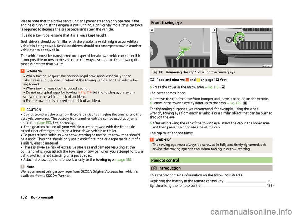
available from a ŠKODA Partner.Front towing eyeFig. 118
Removing the cap/installing the towing eye
Read and observe
and on page 132 first.
›
Press the cover in the arrow area » Fig. 118 -
.
The cover comes loose.
›
Remove the cap from the front bumper and leave it hanging on the vehicle.
›
Screw in the towing eye by hand up to the stop » Fig. 118 -
.
For tightening purposes, we recommend, for example, using the wheel
wrench, towing eye from another vehicle or a similar object that can be pushed
through the eye.
›
After unscrewing the cap of the towing eye, insert the cap in the lower area
and then press the opposite side of the cap.
The cap must engage firmly.
WARNINGThe towing eye must always be screwed in fully and firmly tightened, oth-
erwise the towing eye can tear when towing in or tow-starting.
Remote control
Introduction
This chapter contains information on the following subjects:
Replacing the battery in the remote control key
133
Synchronising the remote control
133
132Do-it-yourself