display SKODA CITIGO 2014 1.G Owner's Guide
[x] Cancel search | Manufacturer: SKODA, Model Year: 2014, Model line: CITIGO, Model: SKODA CITIGO 2014 1.GPages: 164, PDF Size: 12.08 MB
Page 91 of 164
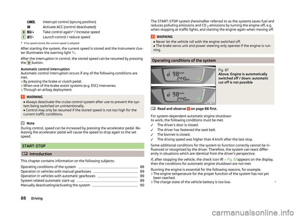
Interrupt control (sprung position) Activate ACC (control deactivated)BTake control againa)
/ Increase speedCLaunch control / reduce speeda)
If no speed stored, the current speed is adopted.
After starting the system, the current speed is stored and the instrument clus-
ter illuminates the warning light
.
After the interruption in control, the stored speed can be resumed by pressing
the
B
button.
Automatic control interruption
Automatic control interruption occurs if any of the following conditions are
met.
› By pressing the brake or clutch pedal.
› When one of the brake assist systems (e.g. ESC) intervenes.
› Through an airbag deployment.
WARNING■
Always deactivate the cruise control system after use to prevent the sys-
tem being switched on unintentionally.■
Control may only be resumed if the stored speed is not too high for the
current traffic conditions.
Note
During control, speed can be increased by pressing the accelerator pedal. Re-
leasing the accelerator pedal will cause the speed to drop again to the set
speed.
START-STOP
Introduction
This chapter contains information on the following subjects:
Operating conditions of the system
88
Operation in vehicles with manual gearboxes
89
Operation in vehicles with automatic gearboxes
89
System related automatic start-up
89
Manually deactivating/activating the system
90The START-STOP system (hereinafter referred to as the system) saves fuel and
reduces polluting emissions and CO 2 emissions by turning the engine off, e.g.
when stopping at traffic lights, and starting the engine again when moving off.WARNING■ Never let the vehicle roll with the engine switched off.■The brake servo unit and power steering only operate if the engine is run-
ning.
Operating conditions of the system
Fig. 87
Above: Engine is automatically
switched off / down: automatic
cut off is not possible
Read and observe on page 88 first.
For system-dependent automatic engine shutdown
to work, the following conditions must be met.
The driver's door is closed.
The driver has fastened the seat belt.
The bonnet is closed.
The driving speed was higher than 4 km/h after the last stop.
Some additional conditions for the system to function correctly cannot be in-
fluenced or recognised by the driver. Therefore, the system can react differ-
ently in situations which are identical from the driver's perspective.
If, after stopping the vehicle, the check icon
» Fig. 87 appears on the display,
then the conditions for automatic engine shutdown are not met.
Running the engine is essential for the following reasons, for example.
› The engine temperature for the proper function of the system has not yet
been reached.
› The charge state of the vehicle battery is too low.
88Driving
Page 92 of 164
›The current consumption is too high.
› High air-conditioning or heating capacity (high fan speed, big difference be-
tween the desired and actual interior temperature).
Note
■ If the vehicle remains outdoors for a long time in minus temperatures or in
direct sunlight, it can take several hours until the internal temperature of the
vehicle battery reaches a suitable temperature for proper operation of the
START STOP system.■
If the driver's seat belt is removed for more than approx. 30 seconds or the
driver's door is opened during stop mode, the engine will have to be started
manually.
■
After the manual engine start and with a manual gearbox the automatic en-
gine shutdown can take place only when a minimum distance required for the
system function has been covered.
Operation in vehicles with manual gearboxes
Read and observe
on page 88 first.
In compliance with the operating conditions, automatic engine shutdown / au-
tomatic engine start takes place as described.
Automatic engine shutdown
›
Stop the vehicle.
›
Put the gear stick into Neutral.
›
Release the clutch pedal.
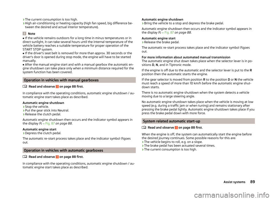
Automatic engine shutdown then occurs and the indicator symbol appears in
the display
» Fig. 87 on page 88 .
Automatic engine start
›
Depress the clutch pedal.
The automatic re-start process takes place and the indicator symbol goes
out.
Operation in vehicles with automatic gearboxes
Read and observe
on page 88 first.
In compliance with the operating conditions, automatic engine shutdown / au-
tomatic engine start takes place as described.
Automatic engine shutdown›Bring the vehicle to a stop and depress the brake pedal.
Automatic engine shutdown then occurs and the indicator symbol appears in
the display
» Fig. 87 on page 88 .
Automatic engine start›
Release the brake pedal.
The automatic re-start process takes place and the indicator symbol
goes
out.
For more information about automated manual transmission
The automatic engine shut down takes place when the selector lever is in po-
sitions D, N , and in Tiptronic mode.
If the engine is off due to the automatic and the selector lever is put to the R
position then the automatic starts the engine.
If the gear selector is moved from position R to the position D or N the vehicle
must reach a speed of more than 10 km/h before the automatic engine shut-
down starts.
There is no automatic engine shutdown when the system detects a vehicle
moving due to a large steering angle.
No automatic engine shutdown takes place when the vehicle is moving at low
speed (e.g. during a traffic jam or when tuning) and remains stationary after
pressing the brake pedal lightly. Automatic engine shutdown takes place if you
press the brake pedal down with more force.
System related automatic start-up
Read and observe
on page 88 first.
When the engine is off, the system can automatically start the engine before
the desired journey continues. Some possible reasons for this are:
› The vehicle begins to roll, e.g. on a slope.
› The brake pedal has been actuated several times.
› The current consumption is too high.
89Assist systems
Page 94 of 164
The system is ready to intervene automatically in the following conditions.The engine is running.
The system is activated.
The travel speed is about 5-30 km/h.
The field of view of the laser sensor is not impaired.
If the system triggers automatic braking, the indicator symbol flashes
in the
display of the instrument cluster quickly.
Automatic braking interventions by the emergency brake function can be ter-
minated by pressing the clutch or the accelerator or by moving the steering
wheel.
The system can, for example, be affected in the following situations or not
be available.
› When visibility is poor, (e.g. fog, heavy rain, thick snowfall).
› Driving around “sharp” bends.
› When fully pressing down the accelerator pedal.
› When the laser sensor is dirty or obscured.
› When the vehicles are very dirty and have a low level of reflection.
If the system is not available or there is a system malfunction, the indicator
symbol flashes
slowly in the display of the instrument cluster.WARNING■
The windscreen may be neither blocked nor covered with dirt in the area
of the laser sensor. This can lead to impaired function of the sensor - risk of
accidents!WARNINGThe laser beam from the laser sensor can cause serious eye injuries. The la-
ser beam is not visible to the human eye.■
Never use optical devices, e.g. a range-finder camera or magnifying glass
to look into the laser sensor.
■
The laser beam can also be active when the system is disabled or is not
available.
CAUTION■ Remove the snow from the windscreen in the area of the laser sensor with a
hand brush and the ice with a solvent-free de-icing spray.■
If the laser sensor range on the windscreen has scratches, cracks, etc, re-
place the windscreen. Only use windscreens approved by the manufacturer.
■
When replacing the windscreen wiper blades, only use windscreen wiper
blades approved by the manufacturer.
Note
If an automatic brake intervention is triggered by the system, the pressure in
the brake system increases and the brake pedal cannot be operated with the
normal pedal stroke.
Disable / Enable
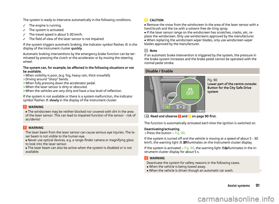
Fig. 90
Lower part of the centre console:
Button for the City Safe Drive
system
Read and observe and on page 90 first.
The function is automatically activated each time the ignition is switched on.
Deactivating/activating
›
Press the button » Fig. 90.
If the system is turned off and the vehicle is moving at a speed of about 5 - 30
km/h, the warning light
illuminates on the instrument cluster display.
If the system is activated » Fig. 90, the warning light
illuminates in the in-
strument cluster display for about 5 s.
WARNINGDeactivate the system for safety reasons in the following cases.■When the vehicle is being towed away.■
When the vehicle is driven though an automatic car wash.
91Assist systems
Page 114 of 164
The oil can be checked and topped up, if the following conditions are satisfied.The vehicle is standing on a horizontal surface.
The engine operating temperature is reached.
The engine is turned off.
The bonnet is open.
Checking the level›
Wait a few minutes until the engine oil flows back into the oil trough.
›
Pull out the dipstick.
›
Wipe the dipstick with a clean cloth and insert it again to the stop.
›
Pull the dipstick out again and check the oil level.
›
Re-insert the dipstick.
The engine consumes a little oil. The oil consumption may be as much as 0.5 l/
1 000 km depending on your style of driving and the conditions under which
you operate your vehicle. Consumption may be slightly higher than this during
the first 5 000 km.
The oil level must be checked at regular intervals.
In case of the oil level being too low, the display of the instrument cluster
shows the control symbol
» page 35 . Check the oil level using the dipstick as
soon as possible. Add oil accordingly.
CAUTION
■ The oil level must never be above the A range » Fig. 100 – there is a risk of
damaging the exhaust system!■
Stop driving if for some reason it is not possible to top up the engine oil
under the current conditions. Switch off the engine and seek assistance from a
specialist garage.
■
If the oil level is above the range
A
,
stop driving! Switch off the engine
and seek assistance from a specialist garage.
Replenishing
Read and observe
and on page 110 first.
›
Unscrew the cap of the engine oil filler opening » Fig. 98 on page 109 .
›
Replenish the oil in portions of 0.5 litres in accordance with the correct speci-
fications » page 110 .
›
Check the oil level » page 110.
›
Screw the lid of the engine oil filler closed carefully.
›
Pull the dipstick out as far as the stop.
Coolant
Introduction
This chapter contains information on the following subjects:
Checking the coolant level
112
Replenishing
112
The coolant provides cooling for the motor.
It consists of water and coolant additive with additives that protect the cooling
system against corrosion and prevents furring.
The coolant additive level in the coolant must be at least 40%.
The coolant additive may be increased to a maximum of 60%.
The correct mixing ratio of water and coolant additive is to be checked if nec- essary by a specialist garage or is to be restored if necessary.
The description of the coolant is shown in the coolant expansion reser-
voir » Fig. 101 on page 112 .
WARNINGThe engine compartment of your car is a hazardous area. The following
warning instructions must be followed at all times when working in the en-
gine compartment » page 107.■
The coolant is harmful to health.
■
Avoid contact with the coolant.
■
Coolant vapours are harmful to health.
■
Never open the end cover of the coolant expansion reservoir while the
engine is still warm. The cooling system is pressurized!
■
When opening the end cover of the coolant expansion reservoir, cover it
with a cloth to protect your face, hands and arms from hot steam or hot
coolant.
■
If any coolant splashes into your eyes, immediately rinse out your eyes
with clear water and contact a doctor as soon as possible.
■
Always keep the coolant in the original container, safe from people who
are not completely independent, especially children - there is a danger of
poisoning!
■
If coolant is swallowed, consult a doctor immediately.
■
Never spill operating fluids over the hot engine - risk of fire.
111Inspecting and replenishing
Page 116 of 164
Brake fluid
Introduction
This chapter contains information on the following subjects:
Checking the brake fluid level
113
Specification
113
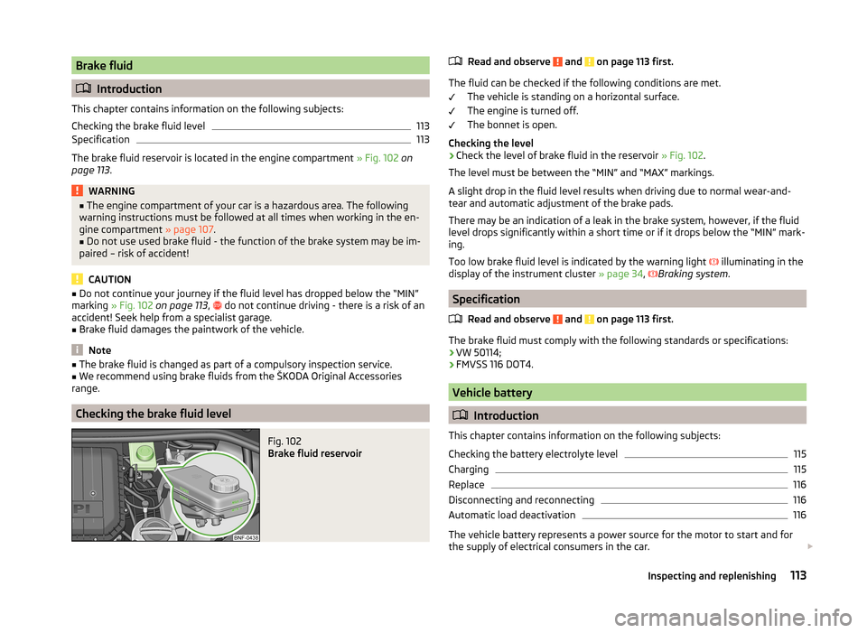
The brake fluid reservoir is located in the engine compartment » Fig. 102 on
page 113 .
WARNING■
The engine compartment of your car is a hazardous area. The following
warning instructions must be followed at all times when working in the en-
gine compartment » page 107.■
Do not use used brake fluid - the function of the brake system may be im-
paired – risk of accident!
CAUTION
■ Do not continue your journey if the fluid level has dropped below the “MIN”
marking » Fig. 102 on page 113 , do not continue driving - there is a risk of an
accident! Seek help from a specialist garage.■
Brake fluid damages the paintwork of the vehicle.
Note
■ The brake fluid is changed as part of a compulsory inspection service.■We recommend using brake fluids from the ŠKODA Original Accessories
range.
Checking the brake fluid level
Fig. 102
Brake fluid reservoir
Read and observe and on page 113 first.
The fluid can be checked if the following conditions are met.
The vehicle is standing on a horizontal surface.
The engine is turned off.
The bonnet is open.
Checking the level
›
Check the level of brake fluid in the reservoir » Fig. 102.
The level must be between the “MIN” and “MAX” markings.
A slight drop in the fluid level results when driving due to normal wear-and-
tear and automatic adjustment of the brake pads.
There may be an indication of a leak in the brake system, however, if the fluid
level drops significantly within a short time or if it drops below the “MIN” mark-
ing.
Too low brake fluid level is indicated by the warning light illuminating in the
display of the instrument cluster » page 34,
Braking system
.
Specification
Read and observe
and on page 113 first.
The brake fluid must comply with the following standards or specifications:› VW 50114;
› FMVSS 116 DOT4.
Vehicle battery
Introduction
This chapter contains information on the following subjects:
Checking the battery electrolyte level
115
Charging
115
Replace
116
Disconnecting and reconnecting
116
Automatic load deactivation
116
The vehicle battery represents a power source for the motor to start and for
the supply of electrical consumers in the car.
113Inspecting and replenishing
Page 118 of 164
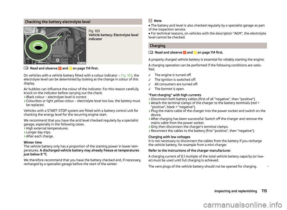
Checking the battery electrolyte levelFig. 103
Vehicle battery: Electrolyte level
indicator
Read and observe and on page 114 first.
On vehicles with a vehicle battery fitted with a colour indicator » Fig. 103, the
electrolyte level can be determined by looking at the change in colour of this
display.
Air bubbles can influence the colour of the indicator. For this reason carefully
knock on the indicator before carrying out the check.
› Black colour – electrolyte level is correct.
› Colourless or light yellow colour – electrolyte level too low, the battery must
be replaced.
Vehicles with a START-STOP system are fitted with a battery control unit for
checking the energy level for the recurring engine start.
We recommend that you have the acid level checked regularly by a specialist
garage, especially in the following cases.
› High external temperatures.
› Longer day trips.
› After each charge.
Winter time
The vehicle battery only has a proportion of the starting power in lower tem-
peratures. A discharged vehicle battery may already freeze at temperatures
just below 0 °C .
We therefore recommend that you have the battery checked and, if necessary,
recharged by a specialist garage before the start of the winter.
Note■ The battery acid level is also checked regularly by a specialist garage as part
of the inspection service.■
For technical reasons, on vehicles with the description “AGM”, the electrolyte
level cannot be checked.
Charging
Read and observe
and on page 114 first.
A properly charged vehicle battery is essential for reliably starting the engine.A charging operation can be performed if the following conditions are satis-
fied.
The engine is turned off.
The ignition is switched off.
All consumers are turned off.
The bonnet is open.
“Fast charging” with high currents
›
Disconnect both battery cables (first of all “negative”, then “positive”).
›
Attach the terminal clamps of the charger to the battery terminals (red =
“positive”, black = “negative”).
›
Plug the mains cable of the charger into the power socket and switch on the
device.
›
After charging has been successful: Switch off the charger and remove the
mains cable from the power socket.
›
Only then disconnect the charger's terminal clamps.
›
Reconnect the cables to the battery (first “positive”, then “negative”).
Charging with low voltages
It is not necessary to disconnect the cables from the battery if you recharge
the vehicle battery, for example from a mini-charger.
Refer to the instructions of the charger manufacturer .
A charging current of 0.1 multiple of the total vehicle battery capacity (or low-
er) must be used until full charging is achieved.
The vent plugs of the vehicle battery should not be opened for charging.
115Inspecting and replenishing
Page 119 of 164
WARNING■When you charge a battery, hydrogen is released, and a highly explosive
gas mixture is also produced. An explosion can be caused through sparkling
over during unclamping or loosening of the cable plug while the ignition is
on.■
Creating a bridge between the poles on the battery (e.g. with metal ob-
jects - cables) creates a short circuit - risk of damage to the battery, explo-
sion and burning of the battery, jets of acid spurting out.
■
Avoid creating sparks when working with cables and electrical devices.
Strong sparking represents a risk of injury.
■
Before carrying out any work on the electrical system, switch off the en-
gine, the ignition and all electrical consumers and disconnect the negative
terminal
.
■
“Quick-charging” the vehicle battery is dangerous and requires a special
charger and specialist knowledge.
■
We therefore recommend that vehicle batteries be “rapidly charged” by a
specialist garage.
CAUTION
On vehicles with the START-STOP system, the pole terminal of the charger
must not be connected directly to the negative terminal of the vehicle battery,
but only to the engine earth » page 130.
Replace
Read and observe
and on page 114 first.
The new vehicle battery must have the same capacity, voltage, current and
size as the original battery. Suitable vehicle battery types can be purchased
from a specialist garage.
We recommend having the battery replaced by a specialist garage, where the
new vehicle battery will be installed properly and the original battery will be
disposed of in accordance with national regulations.
Disconnecting and reconnecting
Read and observe
and on page 114 first.
Disconnecting
›
Switch off the ignition.
›Disconnect the negative terminal
first and then the positive terminal of
the battery.
Connecting›
Connect the positive terminal
first, then the negative
battery terminal.
After disconnecting and re-connecting the vehicle battery, the following func-
tions or devices are partially or completely inoperative.
Function / deviceOperating measureRadioEnter code » operating instruc-
tions for the radioTime settings» page 33
CAUTION
■ Disconnect the vehicle battery only with the ignition turned off - there is a
risk of damaging the electrical system of the vehicle.■
Under no circumstances must the battery cables be connected incorrectly –
risk of a cable fire.
Note
■ After disconnecting and re-connecting the vehicle battery, we recommend
having the vehicle checked by a specialist to ensure that the full functionality
of all electrical systems is guaranteed.■
The data of the multi-function display will be reset.
Automatic load deactivation
Read and observe
and on page 114 first.
The vehicle voltage control unit automatically prevents the battery from dis-
charging when the battery is put under high levels of strain. This manifests it-
self by the following.
› The idling speed is raised to allow the generator to deliver more electricity to
the electrical system.
› Where necessary, large convenience consumers such as seat heaters and
rear window heaters have their power limited or are shut off completely in
the event of an emergency.
116General Maintenance
Page 126 of 164
CAUTION■Screw the jack back into the starting position before storing in the box with
the tool kit.■
Ensure that the vehicle tool kit is safely secured in the luggage compart-
ment.
■
Ensure that the box is always secured with the strap.
Note
The declaration of conformity is included with the jack or the log folder.
Reserve and temporary spare
Introduction
This chapter contains information on the following subjects:
Remove / store wheel
123
Spare wheel
123
If you need to use an emergency or spare wheel, make sure to fit a standard
wheel of the appropriate dimensions and design as soon as possible.
After changing the spare wheel, the tyre pressure should be adjusted. In vehi- cles with tyre pressure monitoring, save tyre pressure values » page 92.
WARNING■
If you have to fit the spare tyre with a non-specified direction or an oppo-
site direction of rotation due to a puncture, then drive carefully. The best
properties of the tyre are no longer present in this situation.■
If the dimensions or design of the spare wheel differ from the tyres fitted
to the vehicle (e.g. winter tyres or low-profile tyres), it must only be used
briefly in the event of a puncture and if an appropriately cautious style of
driving is adopted.
■
If the dimensions or design of the temporary spare wheel differ from the
fitted tyres, never drive faster than 80 km/h (or 50 mph).
■
Never use the temporary spare wheel if it is damaged.
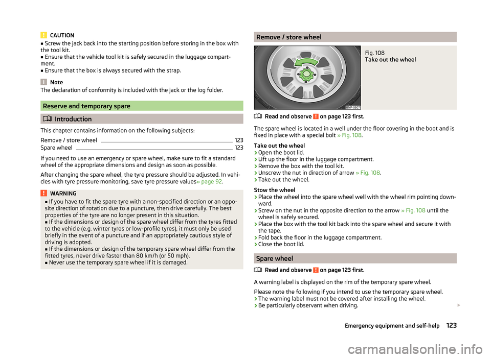
Remove / store wheelFig. 108
Take out the wheel
Read and observe on page 123 first.
The spare wheel is located in a well under the floor covering in the boot and is fixed in place with a special bolt » Fig. 108.
Take out the wheel
›
Open the boot lid.
›
Lift up the floor in the luggage compartment.
›
Remove the box with the tool kit.
›
Unscrew the nut in direction of arrow » Fig. 108.
›
Take out the wheel.
Stow the wheel
›
Place the wheel into the spare wheel well with the wheel rim pointing down-
ward.
›
Screw on the nut in the opposite direction to the arrow » Fig. 108 until the
wheel is safely secured.
›
Place the box with the tool kit back into the spare wheel and secure it with
the tape.
›
Fold back the floor in the luggage compartment.
›
Close the boot lid.
Spare wheel
Read and observe
on page 123 first.
A warning label is displayed on the rim of the temporary spare wheel.
Please note the following if you intend to use the temporary spare wheel. › The warning label must not be covered after installing the wheel.
› Be particularly observant when driving.
123Emergency equipment and self-help
Page 151 of 164
Index
A
abroad lead-free petrol
104
Abroad Headlights
51
ABS Function
85
Warning light37
Acceptance and recycling of used vehicles96
Accessories93
Adjusting Exterior mirrors
54
head restraints56
Interior mirror54
Seat56
Steering wheel10
Adjusting the seats9
Air-conditioning system Air outlet vents
71
Airbag15
Deactivating18
Deactivating the front passenger airbag18
Deployment15
Front airbag16
Modifications and damage to the airbag system 95
Side airbag Head-Thorax
17
Warning light38
Airbag system15
air conditioning recirculation
72
Air conditioning70
Controls71
Air outlet vents71
Alcantara cleaning
102
Alternator Warning light
34
Anti-theft wheel bolts127
Antilock Braking System85
artificial leather102
Ashtray62
Assistance systems City Safe Drive
90
Assist system ABS
85
Assist systems84
ABS37
Cruise Control System87
EDL85
ESC36, 84
HBA85
HHC85
Parking aid85
START-STOP88
TC85
Traction Control System (TCS)36
Visual parking system86
Audio see radio
4
Auto-computer see multi-function display
30
Automated transmission80
Lever control81
Warning light35
Automatic gearbox Tiptronic
81
Automatic load deactivation116
Automatic transmission Kick-down
82
Starting-off and driving82
B
Bag hooks
66
Battery In the remote control key
133
Belts11
Belt tensioners14
Bonnet Closing
108
Opening108
Boot Class N1 vehicles
68
See Boot lid44
Boot lid automatic locking
44
Closing44
Opening44
Brake booster78
brake fluid specification
113
Brake fluid113
Checking113
Brake pedal - automatic transmission indicator light
38
brakes Driving in
82
Brakes Brake booster
78
Brake fluid113
Braking and stabilisation systems84
Handbrake79
Warning lights34
Brakes and parking77
Braking Information on braking
78
Button in driver's door electric windows
44
C
Car care Jack
100
Care and maintenance93
Car park ticket holder60
Carrier Roof rack
68
148Index
Page 152 of 164
Cavity protection100
Central locking39
Central locking button43
Change engine oil
110
Change engine oil
110
Changing Front turn signal bulb
140
Fuses on the underside of the dash panel136
light bulb in tail light141
Low beam and high beam bulb - halogen head- lights
139
Wheels124
Changing a wheel Follow-up work
125
Preliminary work124
Remove and attaching a wheel125
Charging a vehicle battery115
Checking Battery electrolyte level
115
Brake fluid113
Coolant112
Engine oil110
Oil level110
Windscreen washer fluid109
Checks Statutory checks
93
Children and safety19
Child safety Side airbag
21
Child safety lock43
Child seat Classification
22
ISOFIX22
on the front passenger seat20
TOP TETHER23
Use of child seats22
Use of ISOFIX child seats23
Chrome parts see vehicle care99
Cigarette lighter61
City Safe Drive90
Disable/Enable91
Operation90
warning symbol39
cleaning chrome parts
99
Cleaning Alcantara
102
and maintaining belts103
artificial leather102
headlight glasses99
materials102
natural leather101
plastic parts98
seats covers of the electrically heated seats102
wheels100
Cleaning safety belt
103
Cleaning seat covers
102
Cleaning the interior artificial leather
102
Seat covers102
Cleaning the outside of the vehicle Decorative films
99
Cleaning the vehicle exterior Cavity protection
100
Door locking cylinder100
Headlight glasses99
Under-body protection100
wheels100
Windows and external mirrors99
Cleaning vehicle96
Cleaning vehicle exterior97
Plastic parts98
Rubber seals98
Vehicle paint work98
Wiper blades101
Clean interior Safety belt
103
clean outside of vehicle chrome parts
99
Clothes hook64
CNG106
Fuel reserve display29
refuelling105
Refuelling105
Sticker106
Cockpit 12-Volt power outlet
62
Ashtray62
Cigarette lighter61
General view27
Light51
storage compartments60
useful equipment60
compartments60
Components of the puncture repair kits128
Compressed natural gas see CNG
106
Computer see multi-function display
30
convenience turn signal50
Coolant111
Checking112
Replenishing112
Warning light35
Cooling system cost-effective use
72
malfunctions72
Correct seated position9
Driver9
Front passenger10
Instructions11
Rear seats10
Counter for distance driven30
149Index