ad blue SKODA CITIGO 2014 1.G Owner's Manual
[x] Cancel search | Manufacturer: SKODA, Model Year: 2014, Model line: CITIGO, Model: SKODA CITIGO 2014 1.GPages: 164, PDF Size: 12.08 MB
Page 76 of 164
Communication and multimedia
Telephone and Move & Fun
Introduction
This chapter contains information on the following subjects:
Mobile phones and two-way radio systems
73
Multifunction deviceMove & Fun
73
Mobile phones and two-way radio systems
ŠKODA permits the operation of mobile phones and two-way radio systems
with a professionally installed external aerial and a maximum transmission
power of up to 10 watts.
Please consult a ŠKODA Partner for information about the possibility of instal- ling and operating mobile phones and two-way radio systems with a transmis-
sion power of more than 10 W.
Operating mobile phones or two-way radio systems may interfere with the
functionality of the electronic systems in your vehicle.
The possible reasons for this are.
› no external aerial.
› external aerial incorrectly installed.
› transmission power greater than 10 watts.
WARNING■
Concentrate fully at all times on your driving! As the driver you are fully
responsible for the operation of your vehicle. Use the telephone system on-
ly to such an extent that you are in full control of your vehicle at any time.■
The national regulations for using a mobile phone in a vehicle must be
observed.
■
If a mobile phone or a two-way radio system is operated in a vehicle with-
out an external aerial or an external aerial which has been installed incor-
rectly, this can increase the strength of the electromagnetic field inside the
vehicle.
WARNING (Continued)■ Two-way radio systems, mobile phones or mounts must not be installed
on airbag covers or within the immediate deployment range of the airbags.■
Never leave a mobile phone on a seat, on the dash panel or in another
area from which it can be thrown during a sudden braking manoeuvre, an
accident or a collision — risk of injury.
Note
■ We recommend that the installation of mobile phones and two-way radio
systems in a vehicle be carried out by a specialist garage.■
The range of the Bluetooth ®
connection to the hands-free system is restric-
ted to the vehicle interior. The range is dependent on local factors, e.g. obsta-
cles between the devices and mutual interferences with other devices. If your
mobile phone is in a jacket pocket, for example, this can lead to difficulties
when establishing a connection with the hands-free-system or transferring
data.
Multifunction deviceMove & Fun
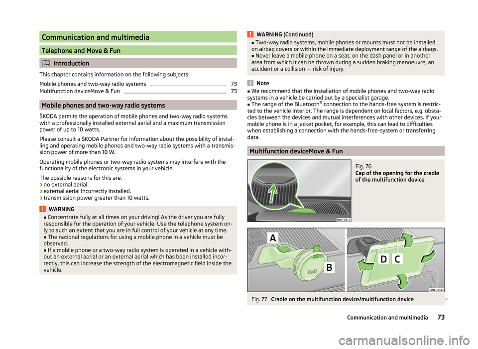
Fig. 76
Cap of the opening for the cradle
of the multifunction device
Fig. 77
Cradle on the multifunction device/multifunction device
73Communication and multimedia
Page 77 of 164
Removing the cap›Insert a slotted screwdriver into the recess marked with an arrow » Fig. 76
and fold the cover carefully upwards.
Installing the cradle for the navigation unit›
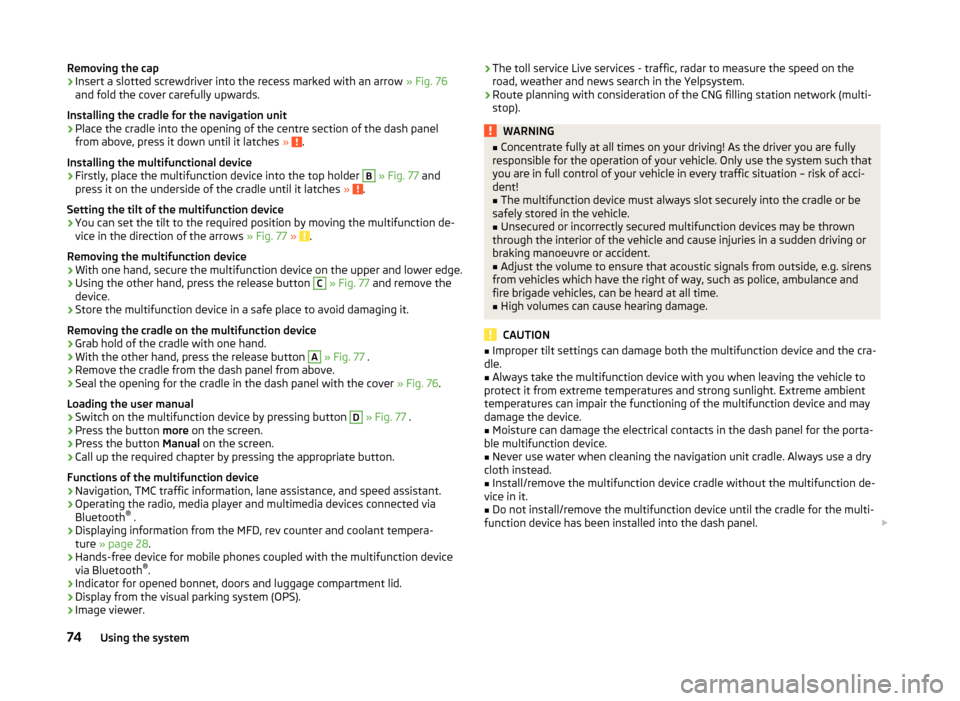
Place the cradle into the opening of the centre section of the dash panel
from above, press it down until it latches » .
Installing the multifunctional device
›
Firstly, place the multifunction device into the top holder
B
» Fig. 77 and
press it on the underside of the cradle until it latches » .
Setting the tilt of the multifunction device
›
You can set the tilt to the required position by moving the multifunction de-
vice in the direction of the arrows » Fig. 77 » .
Removing the multifunction device
›
With one hand, secure the multifunction device on the upper and lower edge.
›
Using the other hand, press the release button
C
» Fig. 77 and remove the
device.
›
Store the multifunction device in a safe place to avoid damaging it.
Removing the cradle on the multifunction device
›
Grab hold of the cradle with one hand.
›
With the other hand, press the release button
A
» Fig. 77 .
›
Remove the cradle from the dash panel from above.
›
Seal the opening for the cradle in the dash panel with the cover » Fig. 76.
Loading the user manual
›
Switch on the multifunction device by pressing button
D
» Fig. 77 .
›
Press the button more on the screen.
›
Press the button Manual on the screen.
›
Call up the required chapter by pressing the appropriate button.
Functions of the multifunction device
› Navigation, TMC traffic information, lane assistance, and speed assistant.
› Operating the radio, media player and multimedia devices connected via
Bluetooth ®
.
› Displaying information from the MFD, rev counter and coolant tempera-
ture » page 28 .
› Hands-free device for mobile phones coupled with the multifunction device
via Bluetooth ®
.
› Indicator for opened bonnet, doors and luggage compartment lid.
› Display from the visual parking system (OPS).
› Image viewer.
›The toll service Live services - traffic, radar to measure the speed on the
road, weather and news search in the Yelpsystem.
› Route planning with consideration of the CNG filling station network (multi-
stop).WARNING■ Concentrate fully at all times on your driving! As the driver you are fully
responsible for the operation of your vehicle. Only use the system such that
you are in full control of your vehicle in every traffic situation – risk of acci-
dent!■
The multifunction device must always slot securely into the cradle or be
safely stored in the vehicle.
■
Unsecured or incorrectly secured multifunction devices may be thrown
through the interior of the vehicle and cause injuries in a sudden driving or
braking manoeuvre or accident.
■
Adjust the volume to ensure that acoustic signals from outside, e.g. sirens
from vehicles which have the right of way, such as police, ambulance and
fire brigade vehicles, can be heard at all time.
■
High volumes can cause hearing damage.
CAUTION
■ Improper tilt settings can damage both the multifunction device and the cra-
dle.■
Always take the multifunction device with you when leaving the vehicle to
protect it from extreme temperatures and strong sunlight. Extreme ambient
temperatures can impair the functioning of the multifunction device and may
damage the device.
■
Moisture can damage the electrical contacts in the dash panel for the porta-
ble multifunction device.
■
Never use water when cleaning the navigation unit cradle. Always use a dry
cloth instead.
■
Install/remove the multifunction device cradle without the multifunction de-
vice in it.
■
Do not install/remove the multifunction device until the cradle for the multi-
function device has been installed into the dash panel.
74Using the system
Page 78 of 164
NoteThe range of the Bluetooth®
connection to the hands-free system is restricted
to the vehicle interior. The range is dependent on local factors, e.g. obstacles
between the devices and mutual interferences with other devices. If your mo-
bile phone is e.g. in a jacket pocket, this can lead to difficulties when establish-
ing the Bluetooth ®
connection with the hands-free system or the data trans-
fer.75Communication and multimedia
Page 90 of 164
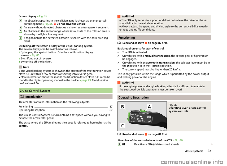
Screen display » Fig. 85
An obstacle appearing in the collision zone is shown as an orange-col-
oured segment » Fig. 85.
Do not drive the vehicle!
An area without detected obstacles is shown as a transparent segment.
An obstacle in the sensor range which lies outside of the collision area is
shown by the light-blue segment.
A region behind the detected obstacle is shown with the dark-blue seg-
ment.
Switching off the screen display of the visual parking system
The screen display can be switched off as follows.
› By tapping the symbol button
in the multifunction display
screen » Fig. 85 .
› By shifting out of reverse.
› By turning off the ignition.
Note
■
The visual parking system is shown in the screen of the multifunction device
Move & Fun within a few seconds of shifting into reverse gear.■
More information about the mobile multifunction device Move & Fun can be
found in the digital operating manual in the device » page 73, Multifunction
deviceMove & Fun .
Cruise Control System
Introduction
This chapter contains information on the following subjects:
Functioning
87
Operating Description
87
The Cruise Control System (CCS) maintains a set speed without you having to
actuate the accelerator pedal.
The state where the GRA maintains the speed is referred to hereinafter as the
control .
ABCDWARNING■
The GRA only serves to support and does not relieve the driver of the re-
sponsibility for the vehicle operation.■
Always adjust the speed and driving style to the current visibility, weath-
er, road and traffic conditions.
Functioning
Read and observe
on page 87 first.
Basic requirements for start of control The GRA is activated.
On vehicles with a manual transmission , the second gear or higher must
be engaged.
On vehicles with an automatic transmission , the selector lever must be in
the D position or in the Tiptronic position.
The current speed must be higher than 20 km/hr.
This is only possible within the range which is permitted by the power output and braking power of the engine.
WARNINGIf the engine power and engine braking effect is insufficient to maintain
the set speed, vehicle operation must be taken over!
Operating Description
Fig. 86
Operating lever: Cruise control
system controls
Read and observe on page 87 first.
Overview of the control elements of the CCS » Fig. 86ADeactivate GRA (delete stored speed) 87Assist systems
Page 138 of 164
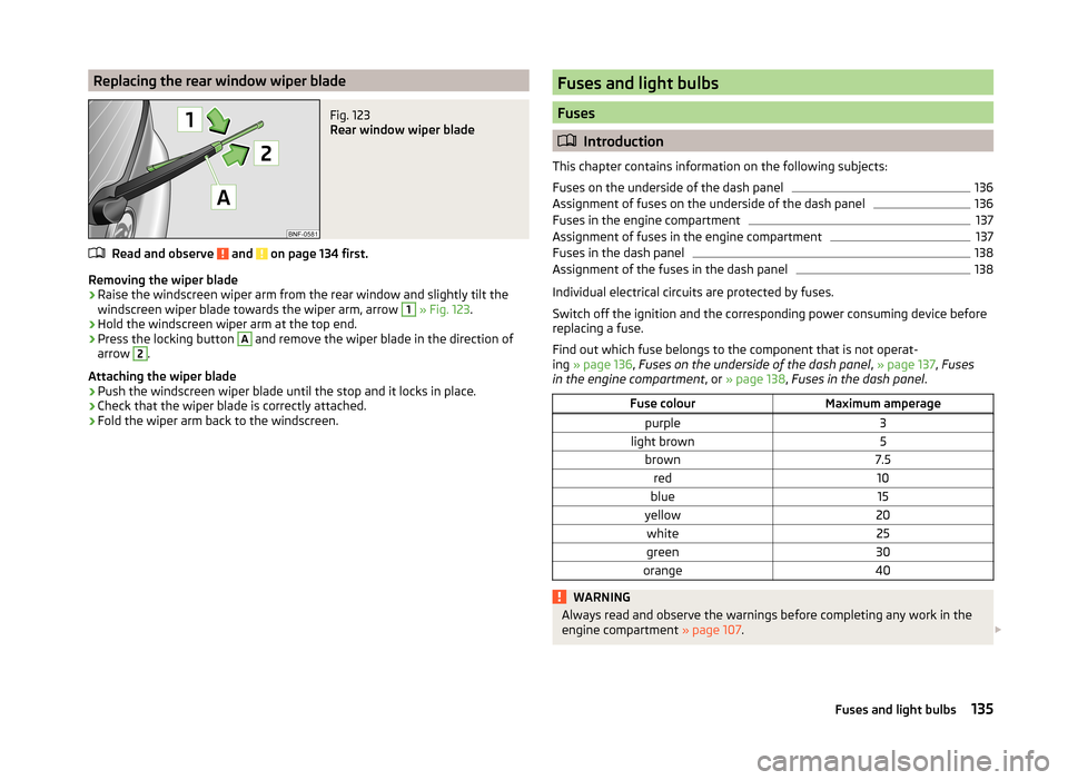
Replacing the rear window wiper bladeFig. 123
Rear window wiper blade
Read and observe and on page 134 first.
Removing the wiper blade
›
Raise the windscreen wiper arm from the rear window and slightly tilt the
windscreen wiper blade towards the wiper arm, arrow
1
» Fig. 123 .
›
Hold the windscreen wiper arm at the top end.
›
Press the locking button
A
and remove the wiper blade in the direction of
arrow
2
.
Attaching the wiper blade
›
Push the windscreen wiper blade until the stop and it locks in place.
›
Check that the wiper blade is correctly attached.
›
Fold the wiper arm back to the windscreen.
Fuses and light bulbs
Fuses
Introduction
This chapter contains information on the following subjects:
Fuses on the underside of the dash panel
136
Assignment of fuses on the underside of the dash panel
136
Fuses in the engine compartment
137
Assignment of fuses in the engine compartment
137
Fuses in the dash panel
138
Assignment of the fuses in the dash panel
138
Individual electrical circuits are protected by fuses.
Switch off the ignition and the corresponding power consuming device before
replacing a fuse.
Find out which fuse belongs to the component that is not operat-
ing » page 136 , Fuses on the underside of the dash panel , » page 137 , Fuses
in the engine compartment , or » page 138 , Fuses in the dash panel .
Fuse colourMaximum amperagepurple3light brown5brown7.5red10blue15yellow20white25green30orange40WARNINGAlways read and observe the warnings before completing any work in the
engine compartment » page 107. 135Fuses and light bulbs