heater SKODA CITIGO 2014 1.G Owner's Manual
[x] Cancel search | Manufacturer: SKODA, Model Year: 2014, Model line: CITIGO, Model: SKODA CITIGO 2014 1.GPages: 164, PDF Size: 12.08 MB
Page 30 of 164
Using the system
Cockpit
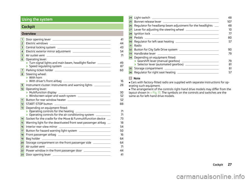
OverviewDoor opening lever
41
Electric windows
44
Central locking system
43
Electric exterior mirror adjustment
54
Air outlet vent
71
Operating lever:
› Turn signal lights and main beam, headlight flasher
49
›Speed regulating system
87
Parking ticket holder
60
Steering wheel:
› With horn
› With driver’s front airbag
16
Instrument cluster: Instruments and warning lights
28
Operating lever:
› Multifunction display
30
›Windscreen wiper and wash system
52
Button for rear window heater
52
START-STOP button
88
Depending on equipment fitted:
› Operating controls for the heating
71
›Operating controls for the air conditioning system
71
Socket for the cradle for the Move & Funmultifunction device
73
Warning light for the deactivated front seat passenger airbag
18
Interior rear-view mirror
54
Button for hazard warning light system
50
Front passenger airbag
16
Bag holder
64
Storage compartment on the front passenger side
64
Air outlet vent
71
Power window in the front passenger door
44
Door opening lever
411234567891011121314151617181920212223Light switch48
Bonnet release lever
107
Regulator for headlamp beam adjustment for the headlights
48
Lever for adjusting the steering wheel
10
Ignition lock
77
Pedals
80
Regulator for left seat heating
57
Radio
Button for City Safe Drive system
90
Handbrake lever
79
Depending on equipment fitted:
› Gearshift lever (manual gearbox)
79
›Selector lever (automated gearbox)
81
Storage compartment
61
Regulator for right seat heating
57
Note
■
Cars with factory-fitted radio are supplied with separate instructions for op-
erating such equipment.■
The arrangement of the controls right-hand drive models may differ from the
layout shown in » Fig. 17. The symbols on the controls and switches are the
same as for left-hand drive models.
2425262728293031323334353627Cockpit
Page 55 of 164
Visibility
Introduction
This chapter contains information on the following subjects:
Rear window heater
52
Sun visors
52
Rear window heater
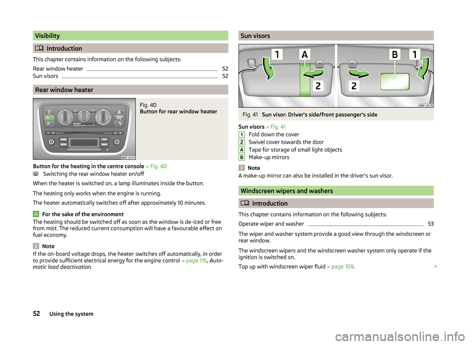
Fig. 40
Button for rear window heater
Button for the heating in the centre console » Fig. 40
Switching the rear window heater on/off
When the heater is switched on, a lamp illuminates inside the button.
The heating only works when the engine is running.
The heater automatically switches off after approximately 10 minutes.
For the sake of the environment
The heating should be switched off as soon as the window is de-iced or free
from mist. The reduced current consumption will have a favourable effect on
fuel economy.
Note
If the on-board voltage drops, the heater switches off automatically, in order
to provide sufficient electrical energy for the engine control » page 116, Auto-
matic load deactivation .Sun visorsFig. 41
Sun visor: Driver's side/front passenger's side
Sun visors » Fig. 41
Fold down the cover
Swivel cover towards the door
Tape for storage of small light objects
Make-up mirrors
Note
A make-up mirror can also be installed in the driver's sun visor.
Windscreen wipers and washers
Introduction
This chapter contains information on the following subjects:
Operate wiper and washer
53
The wiper and washer system provide a good view through the windscreen or
rear window.
The windscreen wipers and the windscreen washer system only operate if the
ignition is switched on.
Top up with windscreen wiper fluid » page 109.
12AB52Using the system
Page 57 of 164
Letting go of the operating lever will cause the windscreen wash system to
stop and the wiper to continue for another 1-3 wiper strokes (depending on
the spraying duration). The operating lever remains in position 6
.
Note
The rear window is wiped once automatically if the windscreen wipers are on
when reverse gear is selected.
Rear mirror
Introduction
This chapter contains information on the following subjects:
Interior mirror
54
Exterior mirrors
54WARNING■ Make sure that the mirror is not covered by ice, snow, mist or other ob-
jects.■
Convex (curved outward) or aspheric exterior mirrors increase the field of
vision. They do, however, make objects appear smaller in the mirror. These
mirrors are therefore only of limited use for estimating distances to the fol-
lowing vehicles.
■
Whenever possible use the interior mirror for estimating the distances to
the following vehicles.
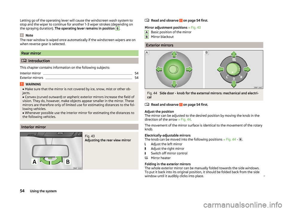
Interior mirror
Fig. 43
Adjusting the rear view mirror
Read and observe on page 54 first.
Mirror adjustment positions » Fig. 43
Basic position of the mirror
Mirror blackout
Exterior mirrors
Fig. 44
Side door - knob for the external mirrors: mechanical and electri-
cal
Read and observe
on page 54 first.
Adjust the position
The mirror can be adjusted to the desired position by moving the knob in the
direction of the arrow » Fig. 44.
The movement of the mirror surface is identical to the movement of the rotary
knob.
Electrically-adjustable mirrors
The knob can be moved into the following positions » Fig. 44 -
.
Adjust the left mirror
Adjust the right mirror
Switch off mirror control
Mirror heater
Folding in the exterior mirrors
The whole exterior mirror can be manually folded towards the side windows. To put it back into its original position, it should be folded back from the side
window until it audibly clicks into place.
AB54Using the system
Page 58 of 164
WARNINGDo not touch the exterior mirror surfaces, if the exterior mirror heating is
switched on - hazard of burning.
Note
■ The mirror heater only operates when the engine is running and up to an
outside temperature of +35 ℃.■
If the electrical mirror setting fails at any time, the mirrors can be adjusted by
hand by pressing on the edge of the mirror surface.
Seats and head restraints
Seats and head restraints
Introduction
This chapter contains information on the following subjects:
Adjusting the front seats
56
Head restraints - adjusting height
56
Headrests - removing and installing
57
The driver's seat should be adjusted in such a way that the pedals can be fully
pressed to the floor with slightly bent legs.
The seat backrest on the driver's seat should be adjusted in such a way that the upper point of the steering wheel can be easily reached with slightly bent
arms.
Correct adjustment of the seats is particularly important for the following: › Reaching the controls safely and quickly,
› A relaxed and fatigue-free body position.
› Achieving the maximum protection offered by the seat belts and the airbag
system.
WARNING■ Only adjust the driver's seat when the vehicle is stationary – risk of acci-
dent!■
Caution when adjusting the seat! You may suffer injuries or bruises as a
result of adjusting the seat without paying proper attention.
■
Never carry more people than there are number of seats in the vehicle.
■
Do not carry any objects on the front passenger seat except objects de-
signed for this purpose (e.g. child seat) – risk of accident!
Note
After a certain time, play can develop within the adjustment mechanism of the
backrest angle.55Seats and head restraints
Page 60 of 164
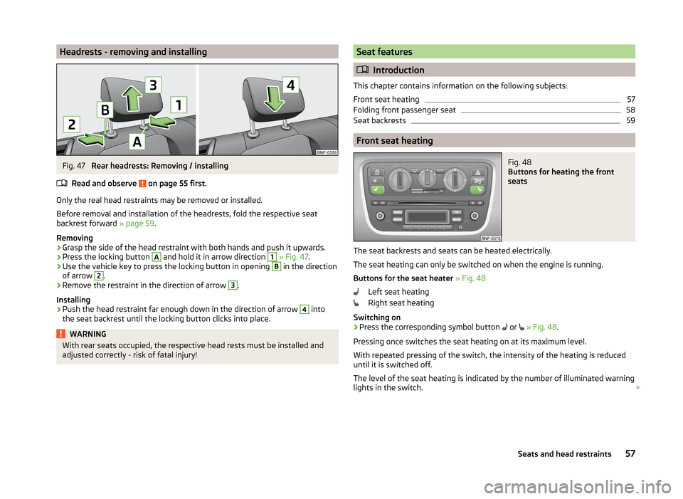
Headrests - removing and installingFig. 47
Rear headrests: Removing / installing
Read and observe
on page 55 first.
Only the real head restraints may be removed or installed.
Before removal and installation of the headrests, fold the respective seat
backrest forward » page 59.
Removing
›
Grasp the side of the head restraint with both hands and push it upwards.
›
Press the locking button
A
and hold it in arrow direction
1
» Fig. 47 .
›
Use the vehicle key to press the locking button in opening
B
in the direction
of arrow
2
.
›
Remove the restraint in the direction of arrow
3
.
Installing
›
Push the head restraint far enough down in the direction of arrow
4
into
the seat backrest until the locking button clicks into place.
WARNINGWith rear seats occupied, the respective head rests must be installed and
adjusted correctly - risk of fatal injury!Seat features
Introduction
This chapter contains information on the following subjects:
Front seat heating
57
Folding front passenger seat
58
Seat backrests
59
Front seat heating
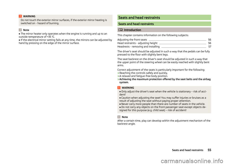
Fig. 48
Buttons for heating the front
seats
The seat backrests and seats can be heated electrically.
The seat heating can only be switched on when the engine is running.
Buttons for the seat heater » Fig. 48
Left seat heating
Right seat heating
Switching on
›
Press the corresponding symbol button or
» Fig. 48 .
Pressing once switches the seat heating on at its maximum level.
With repeated pressing of the switch, the intensity of the heating is reduced
until it is switched off.
The level of the seat heating is indicated by the number of illuminated warning
lights in the switch.
57Seats and head restraints
Page 61 of 164
WARNINGIf, as an occupant, you have a subdued pain and/or temperature sensitivity,
e.g. through medication, paralysis or because of chronic illness (e.g. diabe-
tes), we recommend you do not use seat heating on the driver or front pas-
senger seat. This can lead to burns on the back, the posterior and the legs
which are difficult to heal. If the seat heating is used, we recommend to
make regular breaks in your journey when driving long distances, so that
the body can recuperate from the stress of the journey. Please consult your
doctor, who can evaluate your specific condition.
CAUTION
■ Do not kneel on the seats or otherwise apply concentrated pressure to them.■The seat heating in the following cases will not turn on - there is a risk of
damaging the seat covers and seat heating. ■The seats are not occupied by people.
■ Items are fastened or stored items on the seats, such as a child seat, a bag
and the like.
■ Additional seat covers or protective covers are fixed to the seats.■
Clean the seat covers » page 102, Seat covers .
Note
If the on-board voltage drops, the seat heater switches off automatically, in or-
der to provide sufficient electrical energy for the engine control » page 116,
Automatic load deactivation .
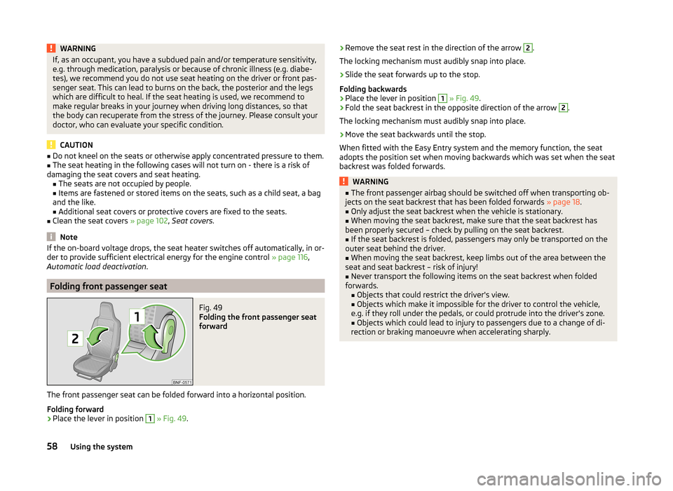
Folding front passenger seat
Fig. 49
Folding the front passenger seat
forward
The front passenger seat can be folded forward into a horizontal position.
Folding forward
›
Place the lever in position
1
» Fig. 49 .
›Remove the seat rest in the direction of the arrow 2.
The locking mechanism must audibly snap into place.›
Slide the seat forwards up to the stop.
Folding backwards
›
Place the lever in position
1
» Fig. 49 .
›
Fold the seat backrest in the opposite direction of the arrow
2
.
The locking mechanism must audibly snap into place.
›
Move the seat backwards until the stop.
When fitted with the Easy Entry system and the memory function, the seat
adopts the position set when moving backwards which was set when the seat
backrest was folded forwards.
WARNING■ The front passenger airbag should be switched off when transporting ob-
jects on the seat backrest that has been folded forwards » page 18.■
Only adjust the seat backrest when the vehicle is stationary.
■
When moving the seat backrest, make sure that the seat backrest has
been properly secured – check by pulling on the seat backrest.
■
If the seat backrest is folded, passengers may only be transported on the
outer seat behind the driver.
■
When moving the seat backrest, keep limbs out of the area between the
seat and seat backrest – risk of injury!
■
Never transport the following items on the seat backrest when folded
forwards. ■Objects that could restrict the driver's view.
■ Objects which make it impossible for the driver to control the vehicle,
e.g. if they roll under the pedals, or could protrude into the driver's zone.
■ Objects which could lead to injury to passengers due to a change of di-
rection or braking manoeuvre when accelerating sharply.
58Using the system
Page 69 of 164
Example: In the event of a frontal collision at a speed of 50 km/h, an object
with a weight of 4.5 kg produces an energy, which corresponds to 20 times its
own weight. This means that it results in a weight of approx. 90 kg “ ”.WARNING■ Always store transported objects in the boot and attach them to the lash-
ing eyes.■
Loose objects can be thrown forward during a sudden manoeuvre or in
case of an accident and can injure the occupants or other road users.
■
Loose objects could hit a deployed airbag and injure occupants – danger
of death!
■
Please note that transporting heavy objects alters the handling proper-
ties of the vehicle due to the displacement of the centre of gravity – risk of
accident! The speed and style of driving must be adjusted accordingly.
■
If the items of luggage or objects are attached to the lashing eyes with
unsuitable or damaged lashing straps, injuries can occur in the event of
braking manoeuvres or accidents. To prevent items of luggage from moving
around, always use suitable lashing straps which must be firmly attached
to the lashing eyes.
■
The transported items must be stowed in such a way that no objects are
able to slip forward on sudden driving or braking manoeuvres – risk of in-
jury!
■
When transporting objects in the luggage compartment that has been en-
larged by folding the rear seats forward, ensure the safety of the passen-
gers transported on the other rear seats » page 10, Correct seated position
for the passengers in the rear seats .
■
If the rear seat next to the folded forward seat is occupied, ensure maxi-
mum safety, e.g. by placing the goods to be transported in such a way that
the seat is prevented from folding back in case of a rear collision.
■
Do not drive with the luggage compartment lid fully opened or slightly
ajar otherwise exhaust gases may get into the interior of the vehicle – risk
of poisoning!
■
Do not exceed the permissible axle loads and permissible gross weight of
the vehicle – risk of accident!
■
Do not transport people in the boot!
CAUTION
■ Please ensure that the heating elements for the rear window heater are not
damaged as a result of abrasive objects.■
Tyre pressure must be adjusted to the load » page 118.
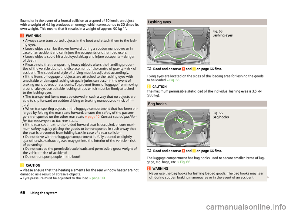
Lashing eyesFig. 65
Lashing eyes
Read and observe and on page 66 first.
Fixing eyes are located on the sides of the loading area for lashing the goods
to be loaded » Fig. 65.
CAUTION
The maximum permissible static load of the individual lashing eyes is 3.5 kN
(350 kg).
Bag hooks
Fig. 66
Bag hooks
Read and observe and on page 66 first.
The luggage compartment has bag hooks used to secure smaller items of lug- gage, e.g. bags, etc. » Fig. 66.
WARNINGNever use the bag hooks for lashing loaded goods. The bag hooks may tear
off during sudden braking manoeuvres or in the event of an accident. 66Using the system
Page 106 of 164
■Electrically heated seats must not be dried after cleaning by switching on the
heater.■
Do not sit on wet seats - risk of seat deformation.
■
Always clean the seats “from seam to seam”.
Safety belts
Read and observe
and on page 101 first.
Wash dirty seat belts with mild soapy water.
Remove coarse dirt with a soft brush.
WARNING■ The seat belts must not be removed for cleaning.■Never clean the seat belts chemically as chemical cleaning products could
destroy the fabric.■
The seat belts must not be allowed to come into contact with corrosive
liquids (e.g. acids).
■
The seat belts must be fully dried before being rolled up.
Inspecting and replenishing
Fuel
Introduction
This chapter contains information on the following subjects:
Petrol Refuelling
104
Lead-free petrol
104
Refuelling CNG (compressed natural gas)
105
CNG
106
The correct fuel grades for your vehicle are specified on the inside of the fuel
filler flap » Fig. 92 on page 104 .
WARNING■
Observe the local regulations regarding fuel handling.■The operating instructions of the refuelling system must always be fol-
lowed.■
Do not smoke when refuelling and do not use a mobile phone.
■
Fuel vapours are explosive - can be fatal!
CAUTION
■ Never drive until the fuel tank is completely empty! The irregular supply of
fuel can cause misfiring, which can result in damage to parts of the engine and
the exhaust system.■
Immediately remove any fuel that has spilled onto the vehicle's paintwork –
risk of paint damage!
■
If the vehicle was not purchased in the country where it was intended to be
operated, you should check whether the fuel specified by the manufacturer is
offered in the country where the vehicle will be operated. You should also per-
haps check whether the manufacturer has recommended a different fuel for
operation of the vehicle in the corresponding country. If no prescribed fuel is
available, then you must check whether it is permitted by the manufacturer to
operate the vehicle with another fuel type.
103Inspecting and replenishing
Page 119 of 164
WARNING■When you charge a battery, hydrogen is released, and a highly explosive
gas mixture is also produced. An explosion can be caused through sparkling
over during unclamping or loosening of the cable plug while the ignition is
on.■
Creating a bridge between the poles on the battery (e.g. with metal ob-
jects - cables) creates a short circuit - risk of damage to the battery, explo-
sion and burning of the battery, jets of acid spurting out.
■
Avoid creating sparks when working with cables and electrical devices.
Strong sparking represents a risk of injury.
■
Before carrying out any work on the electrical system, switch off the en-
gine, the ignition and all electrical consumers and disconnect the negative
terminal
.
■
“Quick-charging” the vehicle battery is dangerous and requires a special
charger and specialist knowledge.
■
We therefore recommend that vehicle batteries be “rapidly charged” by a
specialist garage.
CAUTION
On vehicles with the START-STOP system, the pole terminal of the charger
must not be connected directly to the negative terminal of the vehicle battery,
but only to the engine earth » page 130.
Replace
Read and observe
and on page 114 first.
The new vehicle battery must have the same capacity, voltage, current and
size as the original battery. Suitable vehicle battery types can be purchased
from a specialist garage.
We recommend having the battery replaced by a specialist garage, where the
new vehicle battery will be installed properly and the original battery will be
disposed of in accordance with national regulations.
Disconnecting and reconnecting
Read and observe
and on page 114 first.
Disconnecting
›
Switch off the ignition.
›Disconnect the negative terminal
first and then the positive terminal of
the battery.
Connecting›
Connect the positive terminal
first, then the negative
battery terminal.
After disconnecting and re-connecting the vehicle battery, the following func-
tions or devices are partially or completely inoperative.
Function / deviceOperating measureRadioEnter code » operating instruc-
tions for the radioTime settings» page 33
CAUTION
■ Disconnect the vehicle battery only with the ignition turned off - there is a
risk of damaging the electrical system of the vehicle.■
Under no circumstances must the battery cables be connected incorrectly –
risk of a cable fire.
Note
■ After disconnecting and re-connecting the vehicle battery, we recommend
having the vehicle checked by a specialist to ensure that the full functionality
of all electrical systems is guaranteed.■
The data of the multi-function display will be reset.
Automatic load deactivation
Read and observe
and on page 114 first.
The vehicle voltage control unit automatically prevents the battery from dis-
charging when the battery is put under high levels of strain. This manifests it-
self by the following.
› The idling speed is raised to allow the generator to deliver more electricity to
the electrical system.
› Where necessary, large convenience consumers such as seat heaters and
rear window heaters have their power limited or are shut off completely in
the event of an emergency.
116General Maintenance
Page 140 of 164
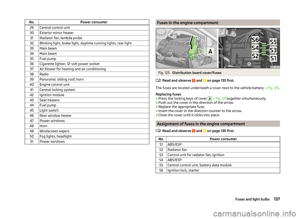
No.Power consumer29Central control unit30Exterior mirror heater31Radiator fan, lambda probe32Blinking light, brake light, daytime running lights, rear light33Main beam34Main beam35Fuel pump36Cigarette lighter, 12-volt power socket37Air blower for heating and air conditioning38Radio39Panoramic sliding roof, horn40Engine control unit41Central locking system42Ignition module43Seat heaters44Fuel pump45Light switch46Rear window heater47Power windows48Horn49Windscreen wipers50Fog lights, headlight51Power windowsFuses in the engine compartmentFig. 125
Distribution board cover/fuses
Read and observe
and on page 135 first.
The fuses are located underneath a cover next to the vehicle battery » Fig. 125.
Replacing fuses
›
Press the locking keys of cover
A
» Fig. 125 together simultaneously.
›
Push out the cover in the direction of the arrow.
›
Replace the appropriate fuse.
›
Insert the cover in the direction counter to the arrow.
›
Close the cover until it clicks into place.
Assignment of fuses in the engine compartment
Read and observe
and on page 135 first.
No.Power consumerS1ABS/ESPS2Radiator fanS3Control unit for radiator fan, ignitionS4ABS/ESPS5Central control unit, battery data moduleS6Ignition lock, starter137Fuses and light bulbs