service SKODA CITIGO 2014 1.G Owner's Manual
[x] Cancel search | Manufacturer: SKODA, Model Year: 2014, Model line: CITIGO, Model: SKODA CITIGO 2014 1.GPages: 164, PDF Size: 12.08 MB
Page 7 of 164
Board literature
You will always find this Owner's and the Service Plan included in the on-
board literature for your vehicle.
Depending on the equipment, the on-board literature can also include the Ra-
dio operating instructions and in some countries also the brochure On the
road .
Owner's Manual
These operating instructions apply to all body variants of the vehicle and all
related model versions as well as all equipment levels .
This owner's manual describes all possible equipment variants without identi-
fying them as special equipment, model variants or market-dependent equip-
ment. Consequently, this vehicle does not contain all of the equipment com-
ponents described in this Owner's Manual.
The level of equipment of your vehicle refers to your purchase contract of the
vehicle. For any questions regarding the scope of equipment, please contact a
ŠKODA Partner.
The Pictures in this manual are for illustrative purposes only. The illustrations
can differ in minor details from your vehicle; they are only intended to provide
general information.
ŠKODA AUTO a.s. pursues a policy of constant product and model develop-
ment. Changes in terms of supply scope are possible at any time with regard to
design, equipment and technology. The information listed in this operating
manual corresponds to the information available at the time of going to press.
It is therefore not possible for legal claims to be made based on the technical
data, illustrations and information contained in this Owner's Manual.
Service schedule
The service schedule includes the documentation of the vehicle handover,
warranty information and service events.
The radio instruction manual
The radio operating instructions contains a description of the operation of the
radio.
On-the-road brochure
The On-the-road brochure contains phone numbers of importers and service
offices in individual countries, together with emergency numbers.4Board literature
Page 8 of 164
Notes
Terms used
The on-board literature contains the following terms relating to the service
work for your vehicle.
- Workshop - a workshop that carries out specialist service tasks
for ŠKODA vehicles. A specialist can be a ŠKODA partner, a ŠKODA serv- ice partner, as well as an independent workshop.
- A Workshop that has been contractually authorized
by the manufacturer ŠKODA AUTO a.s. or its sales partner to perform
service tasks on ŠKODA vehicles and to sell ŠKODA Genuine Parts.
- A company that has been authorized by the manufacturer
ŠKODA AUTO a.s. or its sales partner to sell new ŠKODA vehicles and,
when applicable, to service them using ŠKODA Genuine Parts and sell
ŠKODA Genuine Parts.
Explanation of symbols
An overview of the symbols used in the instruction manual and a brief explan-
ation of their meaning.Reference to the introductory module of a chapter with important infor-
mation and safety warnings.Continuation of the module on the next page.Situations in which the vehicle must be stopped as soon as possible.®Trademark.WARNINGTexts with this symbol draw attention to threats of a serious accident, in-
jury or loss of life .
CAUTION
Texts with this symbol draw attention to the risk of vehicle damage or possible
inoperability of some systems.
For the sake of the environment
Texts with this symbol contain information on environmental protection as
well as tips for economical operation.
Note
Texts with this symbol contain additional information.“Specialist”“ŠKODA service partner”“ŠKODA partner”5Notes
Page 10 of 164
AbbreviationsAbbreviationDefinitionrpmEngine revolutions per minuteABSAnti-lock brake systemAGMVehicle battery typeASGAutomatic gearboxCNGcompressed natural gasCO2Carbon dioxideEDLElectronic differential lockECEEconomic Commission for EuropeEPCEngine performance checkESCElectronic Stability ControlDRim depthEUEuropean UnionG-TECEngine designation at driven by compressed natural gas ve-
hiclesHBAHydraulic brake assistHHCUphill start assistkWKilowatt, measuring unit for the engine outputMGManual gearboxMFDMultifunction displayMPIGasoline engine with a multi-point fuel injectionN1Panel van intended exclusively or mainly for the transporta-
tion of goodsNmNewton meter, measuring unit for the engine torqueOPSvisual parking systemTCSTraction controlTMCService for transmitting traffic information to the driverVINVehicle identification number7Abbreviations
Page 17 of 164
›Insert the lock tongue into the belt buckle
» Fig. 5 – that is part of the seat
until it clicks into place.›
Pull on the belt to check that it has engaged correctly in the lock.
A plastic knob in the belt webbing holds the belt tongue in a position which is
easy to get hold of.
It is important that the belt is properly routed to ensure seat belts offer the
maximum protection.
The shoulder part of the seat belt must never run across the neck but must
roughly run over the middle of the shoulder and fit snugly against the chest.
The lap part of the belt must run across the pelvis, must not be positioned
across the stomach and must always fit snugly » Fig. 6 –
.
Expectant women must also always wear a seat belt. This is the only way of ensuring optimal protection for the unborn child.
On expectant mothers, the lap part of the belt must be positioned as low as possible on the pelvis to avoid exerting any pressure on the lower abdo-
men » Fig. 6 –
.
Releasing
Release the seat belt only when the vehicle is stationary.
›
Press the red button in the belt buckle » Fig. 5 –
, the lock tongue pops
out.
›
Manually guide the belt back so that it is easier to fully roll up the webbing,
the seat belt does not twist.
CAUTION
When releasing the seatbelt ensure that the tongue of the lock does not dam-
age the door trim or other parts of the interior.
Inertia reels and belt tensioners
Introduction
This chapter contains information on the following subjects:
Inertia reels
14
Belt tensioners
14
Inertia reels
Each seat belt is equipped with an inertia reel.
When pulling slowly on the seat belt, the belt can move freely. When pulling
sharply on the seat belt, the movement is locked by the inertia reel.
The belts also lock when full braking, when the car accelerates, when driving
downhill and when cornering.WARNINGIf the seat belt does not lock when pulling sharply on it, have it inspected
immediately by a specialist garage.
Belt tensioners
Safety for the driver and front passenger wearing their seat belts is enhanced
by the belt tensioners fitted to the inertia reels of the front three-point seat
belts.
The three-point seat belts are automatically tensioned in the event of a frontal
collision of a certain severity. The belt tensioners can also be deployed if the
seat belts are not fastened.
The seat belts are automatically tensioned in the event of a collision of a cer-
tain severity.
Belt tensioners are not activated in the event of minor frontal collisions, side
and rear-end collisions, in the case of a rollover and also not in accidents in
which no major forces are produced from the front.
WARNING■ Any work on the belt tensioner system including removal and installation
of system components because of other repair work, must only be carried
out by a specialist garage.■
The protective function of the system is only adequate for a single acci-
dent. If the belt tensioners have been deployed, it is then necessary to re-
place the entire system.
Note
■ Smoke is generated when the belt tensioners are deployed. This is not an in-
dication of a fire in the vehicle.■
When disposing of the vehicle or parts of the belt tensioner system, it is im-
portant to comply with national legal requirements. ŠKODA service partners
are familiar with these regulations and will be able to provide you with de-
tailed information.
14Safety
Page 21 of 164
WARNING■The airbag control unit operates using pressure sensors located in the
front doors. For this reason, no adjustments may be carried out to the
doors or door panels (e.g. installation of additional loudspeakers). Further
information » page 95, Airbags .■
Ensure that there are no excessive forces, such as violent knocks, kicks
etc., impact on the backrests of the seats otherwise the system may be
damaged. The side airbags would not be deployed in such a case!
■
Any seat or protective covers which you fit to the driver or front passen-
ger seats must only be of the type expressly authorized by ŠKODA. In view
of the fact that the airbag inflates out of the backrest of the seat, use of
non-approved seat or protective covers would considerably impair the pro-
tective function of the side airbag.
■
Any damage to the original seat covers in the area of the side airbag mod-
ule must be repaired immediately by a specialist garage.
■
The airbag modules in the front seats must not display any damage,
cracks or deep scratches. It is not permissible to use force in order to open
the modules.
Note
In vehicles with side airbags a label with the lettering is located on the
front seat backrests.
Deactivating airbags
Introduction
This chapter contains information on the following subjects:
Deactivating airbags
18
Deactivating the front passenger airbag
18
Deactivating airbags
Deactivating an airbag should be considered in cases such as the ones below. › If using a rear-facing child seat on the front passenger seat (due to different
legal regulations, the airbag must be deactivated if using a forwards-facing
child seat in some countries) » page 19, Transporting children safely .
› If it is not possible to maintain a distance of at least 25 cm between the mid-
dle of the steering wheel and chest, despite the driver's seat being correctly
adjusted.
› If special attachments are required in the area of the steering wheel because
of a physical disability.
› If different seats have been fitted (e.g. orthopaedic seats without side air-
bags).
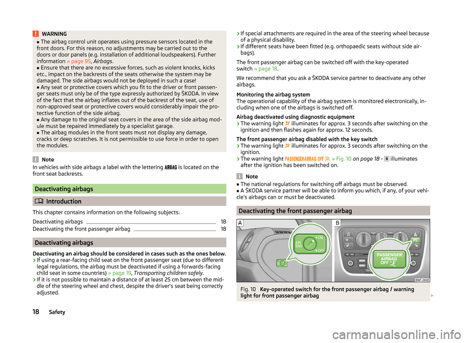
The front passenger airbag can be switched off with the key-operated
switch » page 18 .
We recommend that you ask a ŠKODA service partner to deactivate any other
airbags.
Monitoring the airbag system
The operational capability of the airbag system is monitored electronically, in-
cluding when one of the airbags is switched off.
Airbag deactivated using diagnostic equipment
› The warning light
illuminates for approx. 3 seconds after switching on the
ignition and then flashes again for approx. 12 seconds.
The front passenger airbag disabled with the key switch › The warning light
illuminates for approx. 3 seconds after switching on the
ignition.
› The warning light
» Fig. 10 on page 18 -
illuminates
after the ignition has been switched on.
Note
■ The national regulations for switching off airbags must be observed.■A ŠKODA service partner will be able to inform you which, if any, of your vehi-
cle's airbags can or must be deactivated.
Deactivating the front passenger airbag
Fig. 10
Key-operated switch for the front passenger airbag / warning
light for front passenger airbag
18Safety
Page 31 of 164
Instruments and control lights
Instrument cluster
Introduction
This chapter contains information on the following subjects:
Overview
28
Speedometer
28
Fuel reserve display
29
Tachometer
29
Counter for distance driven
30
Service interval display
30
Gear recommendation
30
The instrument cluster gives the driver basic information such as the current
speed, engine speed, the state of some vehicle systems and the like.
WARNINGConcentrate fully at all times on your driving! As the driver you are fully re-
sponsible for road safety.
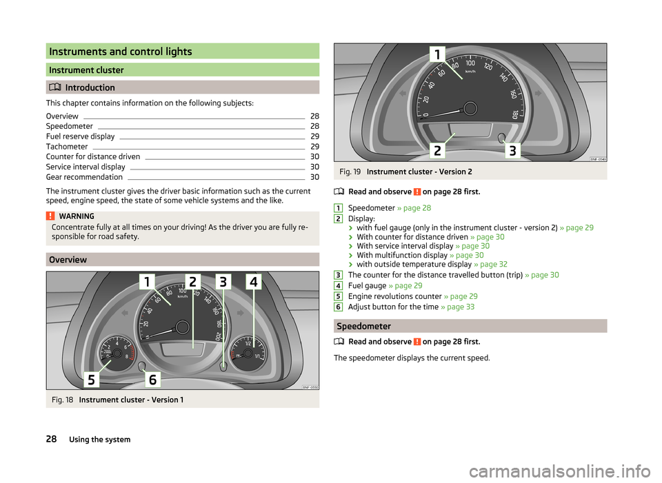
Overview
Fig. 18
Instrument cluster - Version 1
Fig. 19
Instrument cluster - Version 2
Read and observe
on page 28 first.
Speedometer » page 28
Display:
› with fuel gauge (only in the instrument cluster - version 2)
» page 29
› With counter for distance driven
» page 30
› With service interval display
» page 30
› With multifunction display
» page 30
› with outside temperature display
» page 32
The counter for the distance travelled button (trip) » page 30
Fuel gauge » page 29
Engine revolutions counter » page 29
Adjust button for the time » page 33
Speedometer
Read and observe
on page 28 first.
The speedometer displays the current speed.
12345628Using the system
Page 33 of 164
Counter for distance drivenRead and observe
on page 28 first.
To toggle between the odometer and the counter for the distance travelled(trip), briefly press the button
3
» Fig. 18 on page 28 or » Fig. 19 on page 28 .
Counter for distance travelled (trip)
The daily trip counter shows the distance driven since the time the counter
was last reset - in steps of 0.1 km.
Reset counter for distance travelled (trip)
›
Press and hold the
3
» Fig. 18 on page 28 or » Fig. 19 on page 28 button.
Odometer
The odometer indicates the total distance which the vehicle has been driven.
Service interval display
Read and observe
on page 28 first.
The service interval display shows the mileage to the next service event.
Before the next service interval has been reached, the message
appears in
the instrument cluster display for some seconds and the remaining kilometres
are shown after switching on the ignition.
If the time of the service has been reached, an acoustic signal will sound and the message
appears for a few seconds after switching on the ignition.
The information regarding the service intervals can be found in the service
schedule.
Note
Information is retained in the Service Interval Display even after the vehicle
battery is disconnected.
Gear recommendation
Read and observe
on page 28 first.
An information for the engaged gear is shown in the display of the instrument
cluster.
The function of the gear recommendation is to help reduce fuel consumption.
ShowImportanceOptimal gear engaged.Recommendation that you shift to a higher gear.Recommendation that you shift to a lower gear.
Recommended gear
The gear recommendation is intended only for vehicles with a manual trans-
mission or for vehicles with an automatic transmission in manual shift mode
(Tiptronic).
On vehicles with a manual transmission in the display, the recommended gear
and the respective arrow symbol is displayed.
For vehicles with automated manual transmission mode for manual shifting
(Tiptronic), the currently engaged gear and the respective arrow symbol is
shown in the display.
WARNINGThe driver is always responsible for selecting the correct gear in different
driving situations, such as overtaking.
For the sake of the environment
A suitably selected gear has the following advantages.■It helps to reduce fuel consumption.■
It reduces the operating noise.
■
It protects the environment.
■
It benefits the durability and reliability of the engine.
Multi-function display (MFD)
Introduction
This chapter contains information on the following subjects:
Operation
31
Memory
31
Multifunction display details
32
Warning at excessive speeds
33
33
30Using the system
Page 56 of 164
WARNING■Properly maintained windscreen wiper blades are essential for clear visi-
bility and safe driving » page 134.■
Replace the windscreen wiper blades once or twice a year for safety rea-
sons. These can be purchased from a ŠKODA Partner.
■
Do not use the windscreen washer system at low temperatures, without
heating the windscreen beforehand. The window washer fluid could other-
wise freeze on the windscreen and restrict the view to the front.
CAUTION
■ If the ignition is switched off while the windscreen wipers are switched on,
the windscreen wipers will continue wiping in the same mode after the igni-
tion is turned back on. The windscreen wipers could freeze up in cold tempera-
tures between the time the ignition was turned off and when it was turned
back on again.■
In cold temperatures and during the winter, check before the journey or be-
fore switching on the ignition that the wiper blades are not frozen to the
windscreen. If the windscreen wipers are switched on when the blades are fro-
zen to the windscreen, this may damage both the blades and windscreen wip-
er motor!
■
Carefully peel frozen wiper blades off the pane.
■
Remove snow and ice from the windscreen wipers before driving.
■
If the windscreen wipers are handled carelessly, there is a risk of damage to
the windscreen.
■
Do not switch on the ignition if the front wiper arms are retracted. The wiper
arms could damage the paint of the bonnet.
■
If there is an obstacle on the windscreen, the wiper will try to push away the
obstacle. If the obstacle continues to block the wiper, the wiper stops in order
to avoid damaging the wiper. Remove the obstacle and switch the wiper on
again.
Note
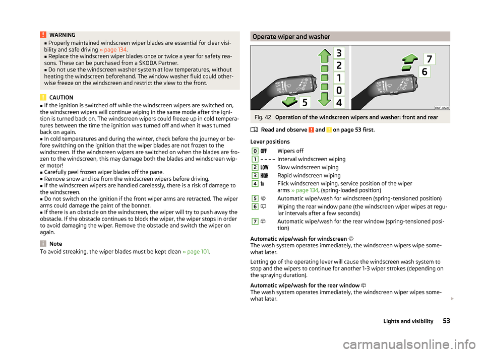
To avoid streaking, the wiper blades must be kept clean » page 101.Operate wiper and washerFig. 42
Operation of the windscreen wipers and washer: front and rear
Read and observe
and on page 53 first.
Lever positions
0Wipers off1 Interval windscreen wiping2Slow windscreen wiping3Rapid windscreen wiping4Flick windscreen wiping, service position of the wiper
arms » page 134 , (spring-loaded position)5Automatic wipe/wash for windscreen (spring-tensioned position)6Wiping the rear window pane (the windscreen wiper wipes at regu-
lar intervals after a few seconds)7Automatic wipe/wash for the rear window (spring-tensioned posi-
tion)
Automatic wipe/wash for windscreen
The wash system operates immediately, the windscreen wipers wipe some-
what later.
Letting go of the operating lever will cause the windscreen wash system to
stop and the wipers to continue for another 1-3 wiper strokes (depending on
the spraying duration).
Automatic wipe/wash for the rear window
The wash system operates immediately, the windscreen wiper wipes some-
what later.
53Lights and visibility
Page 77 of 164
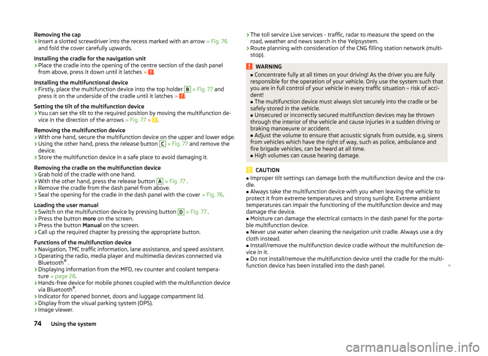
Removing the cap›Insert a slotted screwdriver into the recess marked with an arrow » Fig. 76
and fold the cover carefully upwards.
Installing the cradle for the navigation unit›
Place the cradle into the opening of the centre section of the dash panel
from above, press it down until it latches » .
Installing the multifunctional device
›
Firstly, place the multifunction device into the top holder
B
» Fig. 77 and
press it on the underside of the cradle until it latches » .
Setting the tilt of the multifunction device
›
You can set the tilt to the required position by moving the multifunction de-
vice in the direction of the arrows » Fig. 77 » .
Removing the multifunction device
›
With one hand, secure the multifunction device on the upper and lower edge.
›
Using the other hand, press the release button
C
» Fig. 77 and remove the
device.
›
Store the multifunction device in a safe place to avoid damaging it.
Removing the cradle on the multifunction device
›
Grab hold of the cradle with one hand.
›
With the other hand, press the release button
A
» Fig. 77 .
›
Remove the cradle from the dash panel from above.
›
Seal the opening for the cradle in the dash panel with the cover » Fig. 76.
Loading the user manual
›
Switch on the multifunction device by pressing button
D
» Fig. 77 .
›
Press the button more on the screen.
›
Press the button Manual on the screen.
›
Call up the required chapter by pressing the appropriate button.
Functions of the multifunction device
› Navigation, TMC traffic information, lane assistance, and speed assistant.
› Operating the radio, media player and multimedia devices connected via
Bluetooth ®
.
› Displaying information from the MFD, rev counter and coolant tempera-
ture » page 28 .
› Hands-free device for mobile phones coupled with the multifunction device
via Bluetooth ®
.
› Indicator for opened bonnet, doors and luggage compartment lid.
› Display from the visual parking system (OPS).
› Image viewer.
›The toll service Live services - traffic, radar to measure the speed on the
road, weather and news search in the Yelpsystem.
› Route planning with consideration of the CNG filling station network (multi-
stop).WARNING■ Concentrate fully at all times on your driving! As the driver you are fully
responsible for the operation of your vehicle. Only use the system such that
you are in full control of your vehicle in every traffic situation – risk of acci-
dent!■
The multifunction device must always slot securely into the cradle or be
safely stored in the vehicle.
■
Unsecured or incorrectly secured multifunction devices may be thrown
through the interior of the vehicle and cause injuries in a sudden driving or
braking manoeuvre or accident.
■
Adjust the volume to ensure that acoustic signals from outside, e.g. sirens
from vehicles which have the right of way, such as police, ambulance and
fire brigade vehicles, can be heard at all time.
■
High volumes can cause hearing damage.
CAUTION
■ Improper tilt settings can damage both the multifunction device and the cra-
dle.■
Always take the multifunction device with you when leaving the vehicle to
protect it from extreme temperatures and strong sunlight. Extreme ambient
temperatures can impair the functioning of the multifunction device and may
damage the device.
■
Moisture can damage the electrical contacts in the dash panel for the porta-
ble multifunction device.
■
Never use water when cleaning the navigation unit cradle. Always use a dry
cloth instead.
■
Install/remove the multifunction device cradle without the multifunction de-
vice in it.
■
Do not install/remove the multifunction device until the cradle for the multi-
function device has been installed into the dash panel.
74Using the system
Page 81 of 164
WARNING■Greater physical effort is required for braking when the engine is switch-
ed off – risk of accident!■
The clutch pedal must be actuated when braking on a vehicle with man-
ual gearbox, when the vehicle is in gear and at low revs. Otherwise, the
functionality of the brake system may be impaired – risk of accident!
■
When leaving the vehicle, never leave persons who might, for example,
release the handbrake or take the vehicle out of gear unattended in the ve-
hicle. The vehicle could then start to move – risk of accident!
■
Observe the recommendations on the new brake pads » page 82, New
brake pads .
CAUTION
Never let the brakes slip with light pressure on the pedal if braking is not nec-
essary. This causes the brakes to overheat and can also result in a longer brak-
ing distance and excessive wear.
Information on braking
Read and observe
and on page 78 first.
Wear-and-tear
The wear of the brake pads is dependent on the operating conditions and driv-
ing style.
The brake pads wear more quickly if a lot of journeys are completed in towns
and over short distances or if a very sporty style of driving is adopted.
Under these severe conditions , the thickness of the brake pads must also be
checked by a specialist garage between service intervals.
Wet roads or road salt
The performance of the brakes can be delayed as the brake discs and brake
pads may be moist or have a coating of ice or layer of salt on them in winter.
The brakes are cleaned and dried by applying the brakes several times »
.
Corrosion
Corrosion on the brake discs and dirt on the bake pads occur if the vehicle has
been parked for a long period and if you do not make much use of the braking
system. The brakes are cleaned by applying the brakes several times »
.
Long or steep slopes
Before travelling a long distance with a steep gradient, reduce speed and shift into the next lowest gear. As a result, the braking effect of the engine will be
used, reducing the load on the brakes. Any additional braking should be com-
pleted intermittently, not continuously.
Emergency brake display
If the brakes are applied in full and the control unit for the braking system con-
siders the situation to be dangerous for the following traffic, the brake light
flashes automatically.
After the speed was reduced below around 10 km/h or the vehicle was stop-
ped, the brake light stops flashing and the hazard warning light system
switches on. The hazard warning light system is switched off automatically af-
ter accelerating or driving off again.
Faults in the brake surface
If it is found that the braking distance has suddenly become longer and that
the brake pedal can be depressed further, the brake system may be faulty.
Visit a specialist garage immediately and adjust your style of driving appropri-
ately as you will not know the exact extent of the damage.
Low brake fluid level
An insufficient level of brake fluid may result in problems in the brake system.
The level of the brake fluid is monitored electronically » page 34,
Braking
system .
Brake booster
The brake booster increases the pressure generated with the brake pedal. The
brake booster only operates when the engine is running.WARNINGOnly apply the brakes for the purpose of drying and cleaning the brake
discs if the traffic conditions permit this. Do not place any other road users
in jeopardy.78Driving