air condition SKODA CITIGO 2015 1.G Owner's Guide
[x] Cancel search | Manufacturer: SKODA, Model Year: 2015, Model line: CITIGO, Model: SKODA CITIGO 2015 1.GPages: 160, PDF Size: 23.1 MB
Page 113 of 160
CAUTION■ Do not continue if for some reason it is not possible to fill with coolant un-
der the current circumstances! Switch off the engine and seek assistance from
a specialist garage.■
If the expansion tank is empty, do not top up with coolant. The system could
fill with air - risk of engine damage,
stop driving! Switch off the engine and
seek assistance from a specialist garage.
■
The concentration of coolant additive in the coolant must never be under
40%.
■
Over 60% of coolant additive in the coolant reduces the antifreeze protec-
tion and cooling effect.
■
A coolant additive that does not comply with the correct specification can
significantly reduce the corrosion protection of the cooling system.
■
Any faults resulting from corrosion may cause a loss of coolant and can con-
sequently result in major engine damage.
■
Do not fill the coolant above the mark
A
» Fig. 110 on page 111 .
■
If an error occurs, leading to the engine overheating, the help of a professio-
nal garage is to be sought - there is a risk of serious engine damage occurring.
■
Additional headlights and other attached components in front of the air inlet
impair the cooling efficiency of the coolant.
■
Never cover the radiator - there is a risk of the engine overheating.
Checking the coolant level
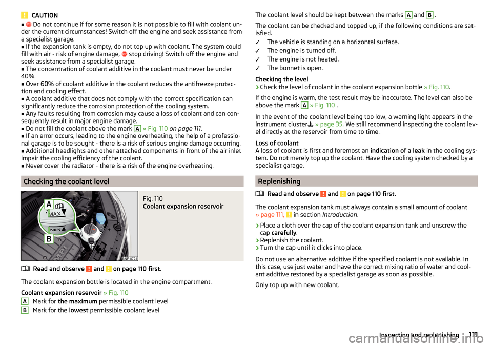
Fig. 110
Coolant expansion reservoir
Read and observe and on page 110 first.
The coolant expansion bottle is located in the engine compartment.
Coolant expansion reservoir » Fig. 110
Mark for the maximum permissible coolant level
Mark for the lowest permissible coolant level
ABThe coolant level should be kept between the marks A and B .
The coolant can be checked and topped up, if the following conditions are sat-
isfied.
The vehicle is standing on a horizontal surface.
The engine is turned off.
The engine is not heated.
The bonnet is open.
Checking the level›
Check the level of coolant in the coolant expansion bottle » Fig. 110.
If the engine is warm, the test result may be inaccurate. The level can also be
above the mark
A
» Fig. 110 .
In the event of the coolant level being too low, a warning light appears in the
instrument cluster
» page 35 . We still recommend inspecting the coolant lev-
el directly at the reservoir from time to time.
Loss of coolant
A loss of coolant is first and foremost an indication of a leak in the cooling sys-
tem. Do not merely top up the coolant. Have the cooling system checked by a
specialist garage.
Replenishing
Read and observe
and on page 110 first.
The coolant expansion tank must always contain a small amount of coolant» page 111, in section Introduction .
›
Place a cloth over the cap of the coolant expansion tank and unscrew the
cap carefully .
›
Replenish the coolant.
›
Turn the cap until it clicks into place.
Do not use an alternative additive if the specified coolant is not available. In
this case, use just water and have the correct mixing ratio of water and cool-
ant additive restored by a specialist garage as soon as possible.
Only top up with new coolant.
111Inspecting and replenishing
Page 114 of 160
Brake fluid
Introduction
This chapter contains information on the following subjects:
Checking the brake fluid level
112
Specification
112
The brake fluid reservoir is located in the engine compartment » Fig. 111 on
page 112 .
WARNING■
The engine compartment of your car is a hazardous area. The following
warning instructions must be followed at all times when working in the en-
gine compartment » page 106.■
Do not use used brake fluid - the function of the brake system may be im-
paired – risk of accident!
CAUTION
■ Do not continue your journey if the fluid level has dropped below the “MIN”
marking » Fig. 111 on page 112 , do not continue driving - there is a risk of an
accident! Seek help from a specialist garage.■
Brake fluid damages the paintwork of the vehicle.
Note
The brake fluid is changed as part of a compulsory inspection service.
Checking the brake fluid level
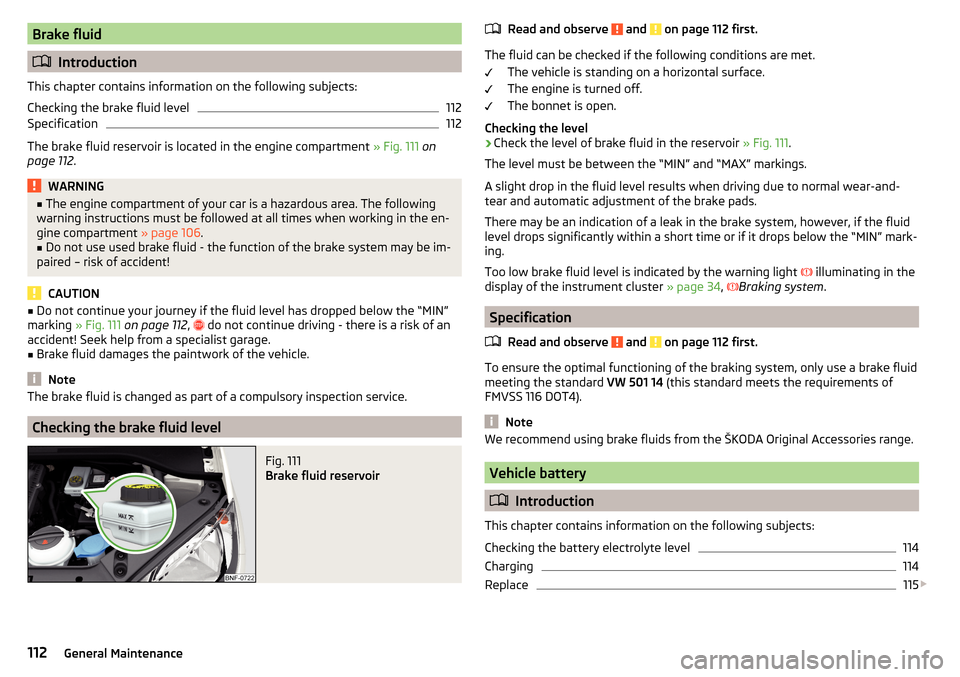
Fig. 111
Brake fluid reservoir
Read and observe and on page 112 first.
The fluid can be checked if the following conditions are met.
The vehicle is standing on a horizontal surface.
The engine is turned off.
The bonnet is open.
Checking the level
›
Check the level of brake fluid in the reservoir » Fig. 111.
The level must be between the “MIN” and “MAX” markings.
A slight drop in the fluid level results when driving due to normal wear-and-
tear and automatic adjustment of the brake pads.
There may be an indication of a leak in the brake system, however, if the fluid
level drops significantly within a short time or if it drops below the “MIN” mark-
ing.
Too low brake fluid level is indicated by the warning light illuminating in the
display of the instrument cluster » page 34,
Braking system
.
Specification
Read and observe
and on page 112 first.
To ensure the optimal functioning of the braking system, only use a brake fluid
meeting the standard VW 501 14 (this standard meets the requirements of
FMVSS 116 DOT4).
Note
We recommend using brake fluids from the ŠKODA Original Accessories range.
Vehicle battery
Introduction
This chapter contains information on the following subjects:
Checking the battery electrolyte level
114
Charging
114
Replace
115
112General Maintenance
Page 116 of 160
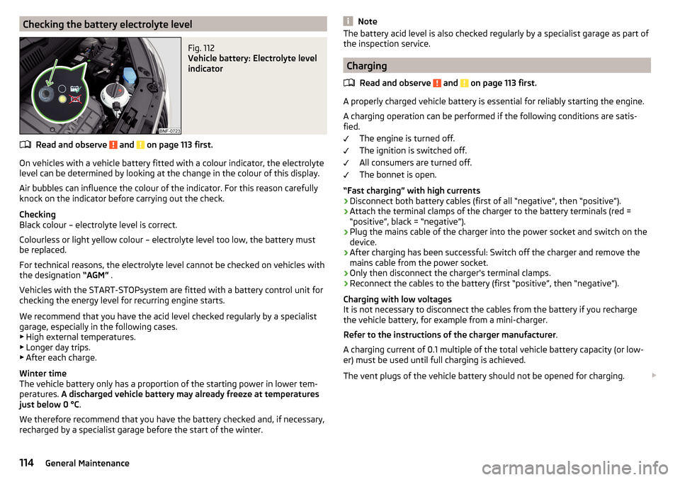
Checking the battery electrolyte levelFig. 112
Vehicle battery: Electrolyte level
indicator
Read and observe and on page 113 first.
On vehicles with a vehicle battery fitted with a colour indicator, the electrolyte
level can be determined by looking at the change in the colour of this display.
Air bubbles can influence the colour of the indicator. For this reason carefully
knock on the indicator before carrying out the check.
Checking
Black colour – electrolyte level is correct.
Colourless or light yellow colour – electrolyte level too low, the battery must
be replaced.
For technical reasons, the electrolyte level cannot be checked on vehicles with
the designation “AGM” .
Vehicles with the START-STOPsystem are fitted with a battery control unit for
checking the energy level for recurring engine starts.
We recommend that you have the acid level checked regularly by a specialist
garage, especially in the following cases. ▶ High external temperatures.
▶ Longer day trips.
▶ After each charge.
Winter time
The vehicle battery only has a proportion of the starting power in lower tem- peratures. A discharged vehicle battery may already freeze at temperatures
just below 0 °C .
We therefore recommend that you have the battery checked and, if necessary,
recharged by a specialist garage before the start of the winter.
NoteThe battery acid level is also checked regularly by a specialist garage as part of
the inspection service.
Charging
Read and observe
and on page 113 first.
A properly charged vehicle battery is essential for reliably starting the engine.
A charging operation can be performed if the following conditions are satis-
fied.
The engine is turned off.
The ignition is switched off.
All consumers are turned off.
The bonnet is open.
“Fast charging” with high currents
›
Disconnect both battery cables (first of all “negative”, then “positive”).
›
Attach the terminal clamps of the charger to the battery terminals (red =
“positive”, black = “negative”).
›
Plug the mains cable of the charger into the power socket and switch on the
device.
›
After charging has been successful: Switch off the charger and remove the
mains cable from the power socket.
›
Only then disconnect the charger's terminal clamps.
›
Reconnect the cables to the battery (first “positive”, then “negative”).
Charging with low voltages
It is not necessary to disconnect the cables from the battery if you recharge
the vehicle battery, for example from a mini-charger.
Refer to the instructions of the charger manufacturer .
A charging current of 0.1 multiple of the total vehicle battery capacity (or low-
er) must be used until full charging is achieved.
The vent plugs of the vehicle battery should not be opened for charging.
114General Maintenance
Page 119 of 160
Always store wheels or tyres in a cool, dry place that is as dark as possible.
Tyres which are not fixed to a wheel trim should be stored upright.
Tyre age
Tyres age and lose their original characteristics, even if they are not being
used. The service life of the tyres is 6 years. Therefore, we recommend not us-
ing tyres that are older than 6 years.
Wheel bolts
Wheels and wheel bolts are matched to each other in terms of design. We rec-
ommend that you use wheel rims and wheel bolts from ŠKODA Original Acces-
sories.WARNINGNever use tyres if you do not know anything about the condition and age.
Tyre pressure
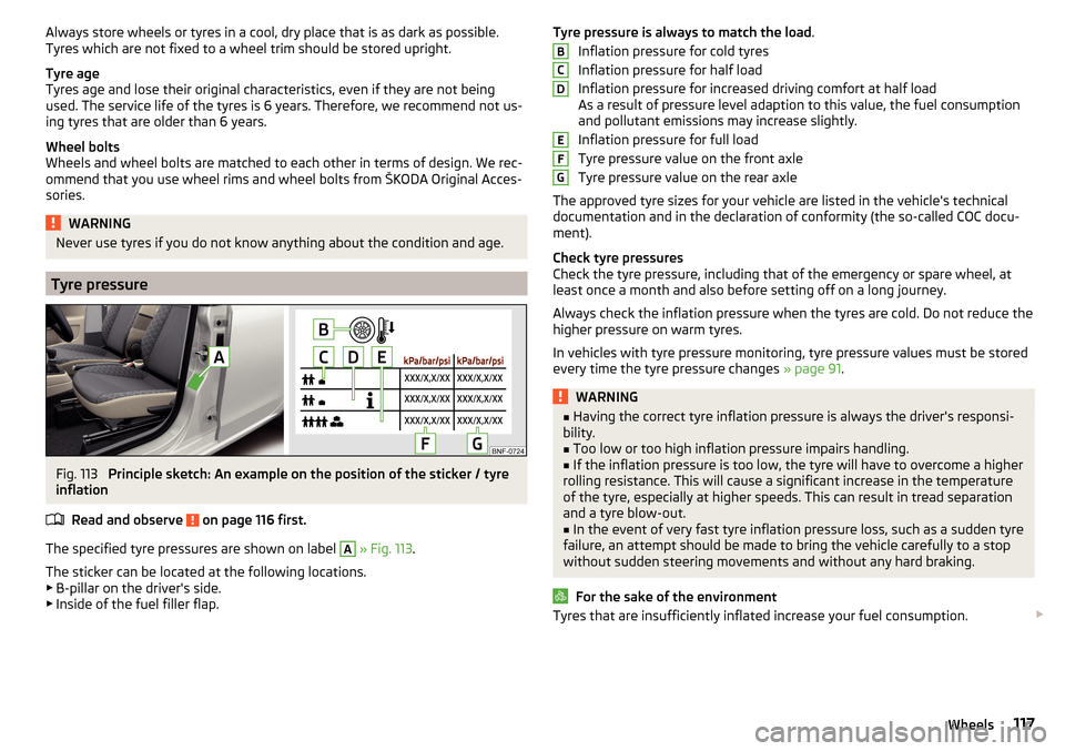
Fig. 113
Principle sketch: An example on the position of the sticker / tyre
inflation
Read and observe
on page 116 first.
The specified tyre pressures are shown on label
A
» Fig. 113 .
The sticker can be located at the following locations.
▶ B-pillar on the driver's side.
▶ Inside of the fuel filler flap.
Tyre pressure is always to match the load .
Inflation pressure for cold tyres
Inflation pressure for half load
Inflation pressure for increased driving comfort at half load
As a result of pressure level adaption to this value, the fuel consumption
and pollutant emissions may increase slightly.
Inflation pressure for full load
Tyre pressure value on the front axle
Tyre pressure value on the rear axle
The approved tyre sizes for your vehicle are listed in the vehicle's technical
documentation and in the declaration of conformity (the so-called COC docu-
ment).
Check tyre pressures
Check the tyre pressure, including that of the emergency or spare wheel, at
least once a month and also before setting off on a long journey.
Always check the inflation pressure when the tyres are cold. Do not reduce the
higher pressure on warm tyres.
In vehicles with tyre pressure monitoring, tyre pressure values must be stored
every time the tyre pressure changes » page 91.WARNING■
Having the correct tyre inflation pressure is always the driver's responsi-
bility.■
Too low or too high inflation pressure impairs handling.
■
If the inflation pressure is too low, the tyre will have to overcome a higher
rolling resistance. This will cause a significant increase in the temperature
of the tyre, especially at higher speeds. This can result in tread separation
and a tyre blow-out.
■
In the event of very fast tyre inflation pressure loss, such as a sudden tyre
failure, an attempt should be made to bring the vehicle carefully to a stop
without sudden steering movements and without any hard braking.
For the sake of the environment
Tyres that are insufficiently inflated increase your fuel consumption. BCDEFG117Wheels
Page 137 of 160
CAUTION■“Never repair” fuses and also do not replace them with a fuse of a higher am-
perage – risk of fire! This may also cause damage at another part of the electri-
cal system.■
If a newly inserted fuse blows again after a short time, have the electrical
system checked as quickly as possible by a specialist garage.
■
A blown fuses is recognisable by the molten metal strip. Replace the faulty
fuse with a new one of the same amperage.
Note
■
We recommend always carrying replacement fuses in the vehicle. A box of
replacement fuses and bulbs can be purchased from ŠKODA Original Accesso-
ries.■
There can be several power consuming devices for one fuse.
■
Multiple fuses may exist for a single power consuming device.
Fuses in the dash panel
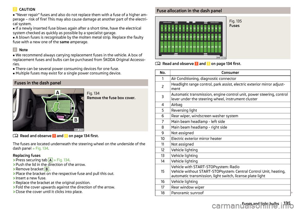
Fig. 134
Remove the fuse box cover.
Read and observe and on page 134 first.
The fuses are located underneath the steering wheel on the underside of the dash panel » Fig. 134.
Replacing fuses
›
Press securing tab
A
» Fig. 134 .
›
Push the lid in the direction of the arrow.
›
Remove bracket
B
.
›
Place the bracket on the respective fuse and pull this out.
›
Insert a new fuse.
›
Replace the bracket at the original position.
›
Fold the cover upwards against the direction of the arrow.
›
Close the cover until it clicks into place.
Fuse allocation in the dash panelFig. 135
Fuses
Read and observe and on page 134 first.
No.Consumer1Air Conditioning, diagnostic connector2Headlight range control, park assist, electric exterior mirror adjust-
ment3Automatic transmission, engine control unit, power steering, control
lever under the steering wheel, instrument cluster4Airbag5Reversing light6Rear wiper, windscreen washer system7Main beam headlamp - left side8Main beam headlamp - right side9Not assigned10Electric exterior mirror heater11Not assigned12Vehicle lighting13Vehicle lighting14Vehicle lighting15Vehicle with START-STOPsystem: Radio
Vehicle without START-STOPsystem: Central Control Unit, heating,
automatic transmission, light switch, license plate light16Vehicle lighting17Rear window wiper18Panoramic sunroof 135Fuses and light bulbs
Page 138 of 160
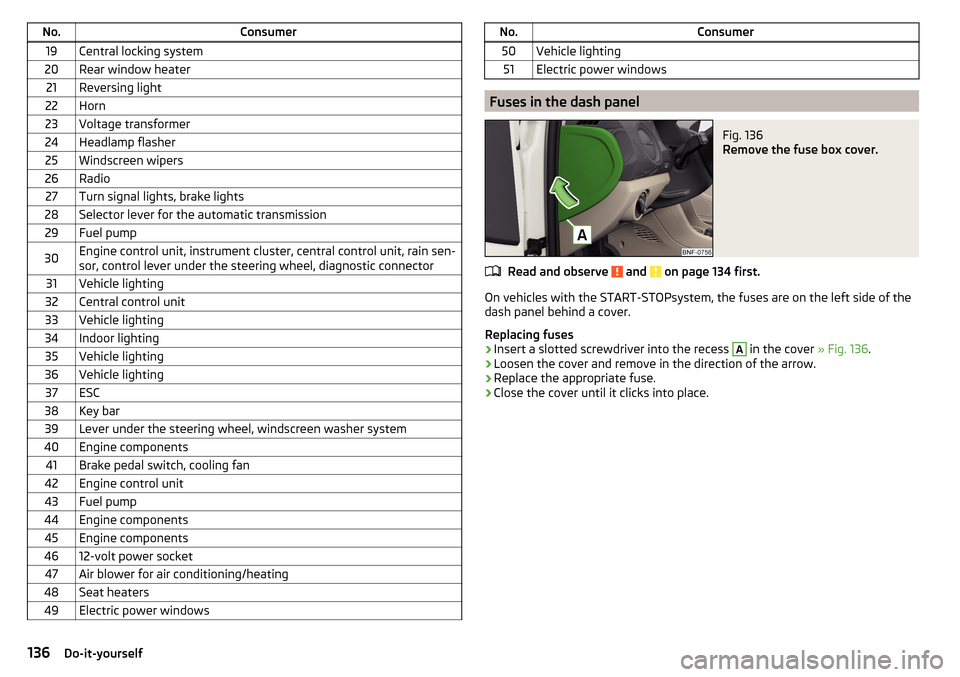
No.Consumer19Central locking system20Rear window heater21Reversing light22Horn23Voltage transformer24Headlamp flasher25Windscreen wipers26Radio27Turn signal lights, brake lights28Selector lever for the automatic transmission29Fuel pump30Engine control unit, instrument cluster, central control unit, rain sen-
sor, control lever under the steering wheel, diagnostic connector31Vehicle lighting32Central control unit33Vehicle lighting34Indoor lighting35Vehicle lighting36Vehicle lighting37ESC38Key bar39Lever under the steering wheel, windscreen washer system40Engine components41Brake pedal switch, cooling fan42Engine control unit43Fuel pump44Engine components45Engine components4612-volt power socket47Air blower for air conditioning/heating48Seat heaters49Electric power windowsNo.Consumer50Vehicle lighting51Electric power windows
Fuses in the dash panel
Fig. 136
Remove the fuse box cover.
Read and observe and on page 134 first.
On vehicles with the START-STOPsystem, the fuses are on the left side of the
dash panel behind a cover.
Replacing fuses
›
Insert a slotted screwdriver into the recess
A
in the cover » Fig. 136.
›
Loosen the cover and remove in the direction of the arrow.
›
Replace the appropriate fuse.
›
Close the cover until it clicks into place.
136Do-it-yourself
Page 139 of 160
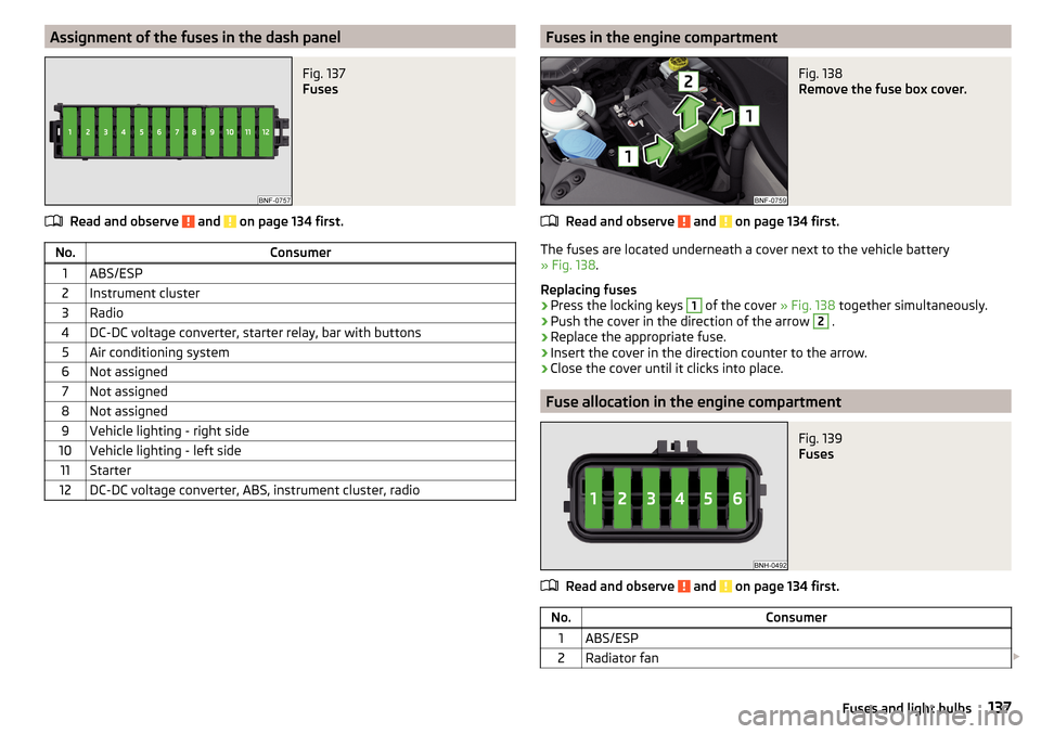
Assignment of the fuses in the dash panelFig. 137
Fuses
Read and observe and on page 134 first.
No.Consumer1ABS/ESP2Instrument cluster3Radio4DC-DC voltage converter, starter relay, bar with buttons5Air conditioning system6Not assigned7Not assigned8Not assigned9Vehicle lighting - right side10Vehicle lighting - left side11Starter12DC-DC voltage converter, ABS, instrument cluster, radioFuses in the engine compartmentFig. 138
Remove the fuse box cover.
Read and observe and on page 134 first.
The fuses are located underneath a cover next to the vehicle battery
» Fig. 138 .
Replacing fuses
›
Press the locking keys
1
of the cover » Fig. 138 together simultaneously.
›
Push the cover in the direction of the arrow
2
.
›
Replace the appropriate fuse.
›
Insert the cover in the direction counter to the arrow.
›
Close the cover until it clicks into place.
Fuse allocation in the engine compartment
Fig. 139
Fuses
Read and observe and on page 134 first.
No.Consumer1ABS/ESP2Radiator fan 137Fuses and light bulbs
Page 144 of 160
Technical data
Technical data
Basic vehicle data
Introduction
This chapter contains information on the following subjects:
Vehicle characteristics
142
Operating weight
143
Payload
143
Measurement of fuel consumption and CO 2 emissions according to ECE
Regulations and EU Directives
143
Dimensions
144
Departure angle
145
The details given in the vehicle's technical documentation always take prece-
dence over the details in the Owner's Manual.
The listed performance values were determined without performance-reduc- ing equipment, e.g. air conditioning system.
The values given have been determined in accordance with regulations and in
conditions prescribed by legal or technical provisions for determining the oper-
ating and technical data of vehicles.
Vehicle characteristics
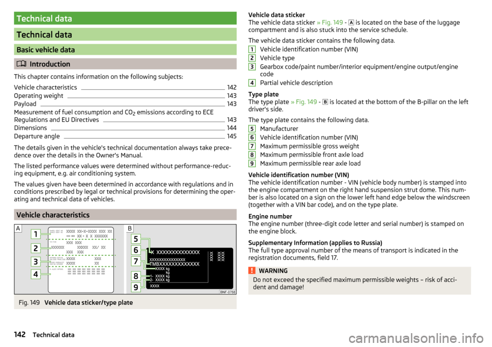
Fig. 149
Vehicle data sticker/type plate
Vehicle data sticker
The vehicle data sticker » Fig. 149 - is located on the base of the luggage
compartment and is also stuck into the service schedule.
The vehicle data sticker contains the following data. Vehicle identification number (VIN)
Vehicle type
Gearbox code/paint number/interior equipment/engine output/engine
code
Partial vehicle description
Type plate
The type plate » Fig. 149 -
is located at the bottom of the B-pillar on the left
driver's side.
The type plate contains the following data. Manufacturer
Vehicle identification number (VIN)
Maximum permissible gross weight
Maximum permissible front axle load
Maximum permissible rear axle load
Vehicle identification number (VIN)
The vehicle identification number - VIN (vehicle body number) is stamped into
the engine compartment on the right hand suspension strut dome. This num-
ber is also located on a sign on the lower left hand edge below the windscreen
(together with a VIN bar code), and on the type plate.
Engine number
The engine number (three-digit code letter and serial number) is stamped on the engine block.
Supplementary Information (applies to Russia)
The full type approval number of the means of transport is indicated in the
registration documents, field 17.WARNINGDo not exceed the specified maximum permissible weights – risk of acci-
dent and damage!123456789142Technical data
Page 145 of 160
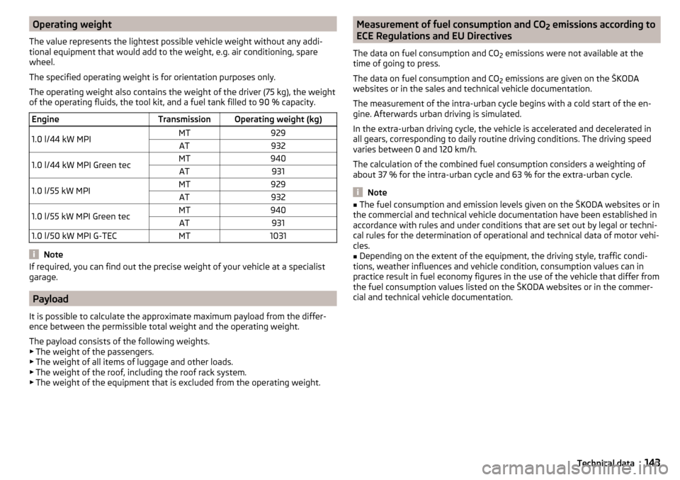
Operating weight
The value represents the lightest possible vehicle weight without any addi-
tional equipment that would add to the weight, e.g. air conditioning, spare
wheel.
The specified operating weight is for orientation purposes only.
The operating weight also contains the weight of the driver (75 kg), the weight
of the operating fluids, the tool kit, and a fuel tank filled to 90 % capacity.EngineTransmissionOperating weight (kg)1.0 l/44 kW MPIMT929AT9321.0 l/44 kW MPI Green tecMT940AT9311.0 l/55 kW MPIMT929AT9321.0 l/55 kW MPI Green tecMT940AT9311.0 l/50 kW MPI G-TECMT1031
Note
If required, you can find out the precise weight of your vehicle at a specialist
garage.
Payload
It is possible to calculate the approximate maximum payload from the differ-
ence between the permissible total weight and the operating weight.
The payload consists of the following weights.
▶ The weight of the passengers.
▶ The weight of all items of luggage and other loads.
▶ The weight of the roof, including the roof rack system.
▶ The weight of the equipment that is excluded from the operating weight.
Measurement of fuel consumption and CO
2 emissions according to
ECE Regulations and EU Directives
The data on fuel consumption and CO 2 emissions were not available at the
time of going to press.
The data on fuel consumption and CO 2 emissions are given on the ŠKODA
websites or in the sales and technical vehicle documentation.
The measurement of the intra-urban cycle begins with a cold start of the en-
gine. Afterwards urban driving is simulated.
In the extra-urban driving cycle, the vehicle is accelerated and decelerated in
all gears, corresponding to daily routine driving conditions. The driving speed
varies between 0 and 120 km/h.
The calculation of the combined fuel consumption considers a weighting of
about 37 % for the intra-urban cycle and 63 % for the extra-urban cycle.
Note
■ The fuel consumption and emission levels given on the ŠKODA websites or in
the commercial and technical vehicle documentation have been established in
accordance with rules and under conditions that are set out by legal or techni-
cal rules for the determination of operational and technical data of motor vehi-
cles.■
Depending on the extent of the equipment, the driving style, traffic condi-
tions, weather influences and vehicle condition, consumption values can in
practice result in fuel economy figures in the use of the vehicle that differ from
the fuel consumption values listed on the ŠKODA websites or in the commer-
cial and technical vehicle documentation.
143Technical data
Page 149 of 160
Index
A
abroad lead-free petrol
103
Abroad Headlights
50
ABS Operation
85
Warning light36
Acceptance and recycling of used vehicles95
Accessories92
Adjusting Exterior mirrors
53
head restraints54
Seat54
Steering wheel9
Adjusting the seats8
Air-conditioning system Air outlet vents
71
Airbag14
Deactivating17
Deactivating the front passenger airbag18
Deployment15
Front airbag15
Modifications and damage to the airbag system 94
Side airbag Head-Thorax
17
Warning light37
Airbag system14
air conditioning recirculation
70
Air conditioning69
Controls69
Air outlet vents71
Alcantara cleaning
101
Alternator Warning light
35
Anodized partsRefer to vehicle maintenance98
Anti-lock braking system (ABS)85
Anti-theft wheel bolts124
artificial leather101
Ashtray61
Assistance systems City Safe Drive
89
Parking aid86
Assistance Systems ESC
36
Assist systems85
ABS36
Cruise Control System88
Visual parking system87
Auto-computer see multi-function display
31
Automated transmission81
Lever control81
Warning light35
Automatic gearbox Tiptronic
82
Automatic load deactivation115
Automatic transmission Kick-down
82
Starting-off and driving82
Avoiding damage to your vehicle84
B
Bag hooks
65
Battery In the remote control key
132
Belts11
Belt tensioners13
Bonnet Closing
107
Opening107
Boot Class N1 vehicles67
See Boot lid43
Boot lid automatic locking
43
Closing43
Opening43
Brake Assist (HBA)86
Brake booster79
brake fluid specification
112
Brake fluid112
Checking112
Brake pedal - automatic transmission warning light
38
Brakes Brake booster
79
Brake fluid112
Braking and stabilisation systems85
Handbrake79
Running-in83
Warning lights34
Brakes and parking78
Brake system85
Braking Information on braking
78
Button in driver's door electric windows
44
C
Car care Jack
99
Care and maintenance92
Car park ticket holder58
Carrier Roof rack
67
Cavity protection99
Central locking39
problems42
147Index