bulb SKODA CITIGO 2015 1.G Owner's Manual
[x] Cancel search | Manufacturer: SKODA, Model Year: 2015, Model line: CITIGO, Model: SKODA CITIGO 2015 1.GPages: 160, PDF Size: 23.1 MB
Page 4 of 160
Table of Contents
Board literature4
Notes
5
Structure and more information about the
Owner's Manual
6
Abbreviations
Safety
Passive Safety
8
General information
8
Correct and safe seated position
8
Seat belts
11
Using seat belts
11
Inertia reels and belt tensioners
13
Airbag system
14
Description of the airbag system
14
Airbag overview
15
Deactivating airbags
17
Transporting children safely
19
Child seat
19
Fastening systems
22
Using the system
Cockpit
27
Overview
26
Instruments and control lights
28
Instrument cluster
28
Multi-function display (MFD)
31
Warning lights
34
Unlocking and opening
39
Unlocking and locking
39
Luggage compartment lid
42Window operations43Panorama sliding/tilting roof45
Lights and visibility
47
Lights
47
Indoor Lighting
50
Visibility
50
Windscreen wipers and washers
51
Rear mirror
52
Seats and head restraints
54
Seats and head restraints
54
Seat features
55
Transporting and practical equipment
58
Useful equipment
58
Luggage compartment and transporting
cargo
64
Roof rack
67
Heating and ventilation
69
Heating, manual air conditioning system
69
Communication and multimedia
72
Telephone and Move & Fun
72
Driving
Starting-off and Driving
75
Starting and turning off the engine
75
START-STOPsystem
77
Brakes and parking
78
Manual gear changing and pedals
80
Automated transmission
81
Running-in and economical driving
83
Avoiding damage to your vehicle
84
Assist systems
85
General information
85
Braking and stabilisation systems
85
Parking aid (ParkPilot)
86
Cruise Control System
88City Safe Drive89Tyre pressure monitoring90
General Maintenance
Care and maintenance
92
Modifications, adjustments and technical
alterations
92
Washing vehicle
95
Cleaning vehicle exterior
96
Interior care
100
Inspecting and replenishing
102
Fuel
102
Engine compartment
106
Engine oil
109
Coolant
110
Brake fluid
112
Vehicle battery
112
Wheels
116
Tyres and wheel rims
116
Winter operation
120
Do-it-yourself
Emergency equipment and self-help
122
Emergency equipment
122
Changing a wheel
123
Puncture repair kit
127
Jump-starting
129
Towing the vehicle
130
Remote control
132
Emergency unlocking/locking
132
Replacing windscreen wiper blades
133
Fuses and light bulbs
134
Fuses
134
Replacing bulbs
1382Table of Contents
Page 96 of 160
ŠKODA service partners are liable for any ŠKODA Genuine Part defects for aperiod of 2 years after installation or delivery in accordance with the materials
defect liability, provided that nothing else was agreed in the purchase contract
or in any other agreements. You should keep the approved warranty certificate
and the bill for these components for this period of time, so that commence-
ment of the term may be verified.
In addition, ŠKODA Service Partners also stock a range of suitable car care
products as well as those parts which are subject to natural wear-and-tear,
such as tyres, batteries, bulbs and wiper blades.
Note
The accessories authorized by the company ŠKODA AUTO a.s. will be offered
by the ŠKODA partners in all countries where the company ŠKODA AUTO a.s.
has a sales and service network. This will usually be in the form of a printed
catalogue of Original ŠKODA Accessories, in the form of separate printed bro-
chures or in the form of offers for ŠKODA Genuine Accessories on the ŠKODA
partner web pages.
Spoiler
Read and observe
on page 92 first.
If your new vehicle is fitted with a spoiler on the front bumper in combination
with the spoiler on the luggage compartment lid, the following instructions
must be adhered to. ▶ For safety reasons, the vehicle must only be fitted with a spoiler on the front
bumper in combination with the associated spoiler on the luggage compart-
ment lid.
▶ This kind of spoiler cannot be left on the front bumper either on its own, in
combination with another spoiler not on the luggage compartment lid or in
combination with an unsuitable spoiler on the luggage compartment lid.
▶ We recommend that you consult the ŠKODA service partner for any repairs to
or replacement, addition or removal of spoilers.
WARNING■ If work on your vehicle's spoilers is not carried out properly, this can lead
to operational faults - risk of accident and serious injuries.■
If a front spoiler, full wheel trim, etc. is mounted retrospectively, it must
be ensured that the air supply to the front wheel brakes is not reduced.
The front brakes may overheat, which can have a negative impact on the
functioning of the braking system – risk of accident!
Airbags
Read and observe
on page 92 first.
WARNING■Modifications, repairs and technical alterations that have been carried out
unprofessionally can cause damage and operational faults, and can also se-
riously impair the effectiveness of the airbag system – risk of accident and
fatal injury!■
A change to the vehicle's wheel suspension, including the use of non-ap-
proved wheels and tire combinations, can alter the functioning of the air-
bag system - risk of accident and fatal injury!
WARNINGInformation on the use of the airbag system■Never install any airbag parts into the vehicle that have been removed
from old cars or have been recycled.■
Never install damaged airbag parts in the vehicle. The airbags may then
not be deployed properly or even at all in the event of an accident.
WARNING■ No modifications of any kind must be made to parts of the airbag system.■Any work on the airbag system including the installation and removal of
system components due to other repair work (e.g. removal of the steering
wheel) must only be carried out by a specialist garage.■
Never make any changes to the front bumper or the bodywork.
■
It is prohibited to manipulate individual parts of the airbag system, as this
might result in the airbag being deployed.
■
The protective function of the airbag system is sufficient for only one ac-
cident. The airbag system must then be replaced if the airbag has been de-
ployed.
94General Maintenance
Page 136 of 160
Attaching the wiper blade›Push the windscreen wiper blade until the stop and it locks in place.›
Check that the wiper blade is correctly attached.
›
Fold the wiper arm back to the windscreen.
›
Turn on the ignition and press the lever into the direction of the arrow
» Fig. 131 .
The windscreen wiper arms move into the home position.
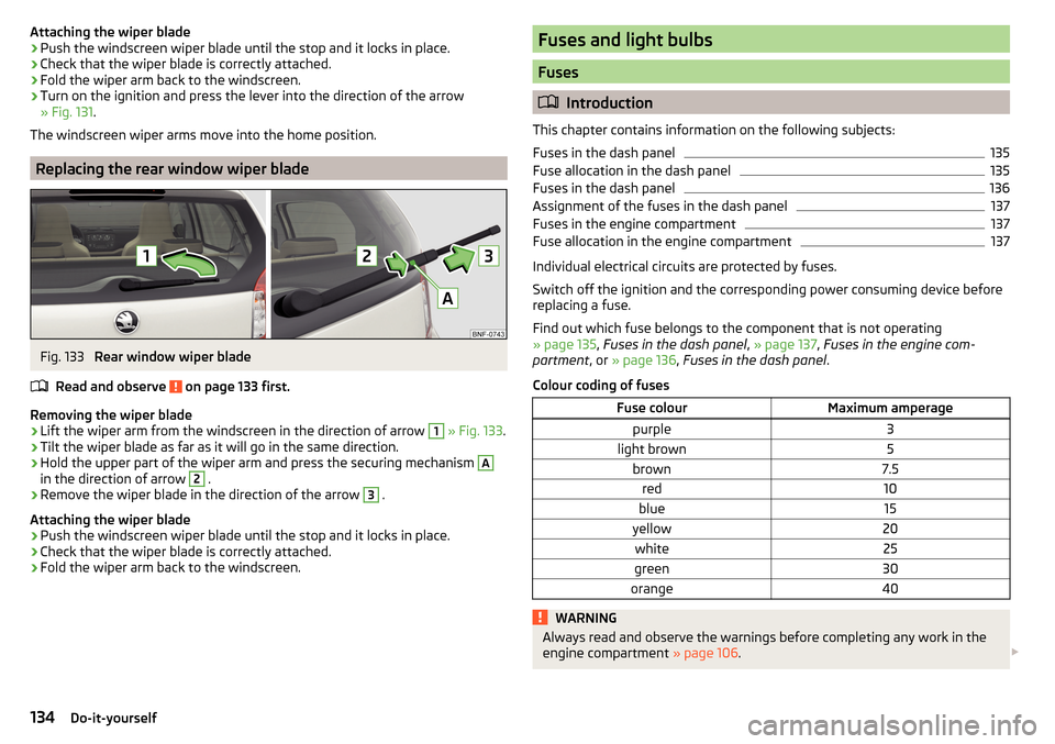
Replacing the rear window wiper blade
Fig. 133
Rear window wiper blade
Read and observe
on page 133 first.
Removing the wiper blade
›
Lift the wiper arm from the windscreen in the direction of arrow
1
» Fig. 133 .
›
Tilt the wiper blade as far as it will go in the same direction.
›
Hold the upper part of the wiper arm and press the securing mechanism
A
in the direction of arrow
2
.
›
Remove the wiper blade in the direction of the arrow
3
.
Attaching the wiper blade
›
Push the windscreen wiper blade until the stop and it locks in place.
›
Check that the wiper blade is correctly attached.
›
Fold the wiper arm back to the windscreen.
Fuses and light bulbs
Fuses
Introduction
This chapter contains information on the following subjects:
Fuses in the dash panel
135
Fuse allocation in the dash panel
135
Fuses in the dash panel
136
Assignment of the fuses in the dash panel
137
Fuses in the engine compartment
137
Fuse allocation in the engine compartment
137
Individual electrical circuits are protected by fuses.
Switch off the ignition and the corresponding power consuming device before
replacing a fuse.
Find out which fuse belongs to the component that is not operating
» page 135 , Fuses in the dash panel , » page 137 , Fuses in the engine com-
partment , or » page 136 , Fuses in the dash panel .
Colour coding of fuses
Fuse colourMaximum amperagepurple3light brown5brown7.5red10blue15yellow20white25green30orange40WARNINGAlways read and observe the warnings before completing any work in the
engine compartment » page 106. 134Do-it-yourself
Page 137 of 160
CAUTION■“Never repair” fuses and also do not replace them with a fuse of a higher am-
perage – risk of fire! This may also cause damage at another part of the electri-
cal system.■
If a newly inserted fuse blows again after a short time, have the electrical
system checked as quickly as possible by a specialist garage.
■
A blown fuses is recognisable by the molten metal strip. Replace the faulty
fuse with a new one of the same amperage.
Note
■
We recommend always carrying replacement fuses in the vehicle. A box of
replacement fuses and bulbs can be purchased from ŠKODA Original Accesso-
ries.■
There can be several power consuming devices for one fuse.
■
Multiple fuses may exist for a single power consuming device.
Fuses in the dash panel
Fig. 134
Remove the fuse box cover.
Read and observe and on page 134 first.
The fuses are located underneath the steering wheel on the underside of the dash panel » Fig. 134.
Replacing fuses
›
Press securing tab
A
» Fig. 134 .
›
Push the lid in the direction of the arrow.
›
Remove bracket
B
.
›
Place the bracket on the respective fuse and pull this out.
›
Insert a new fuse.
›
Replace the bracket at the original position.
›
Fold the cover upwards against the direction of the arrow.
›
Close the cover until it clicks into place.
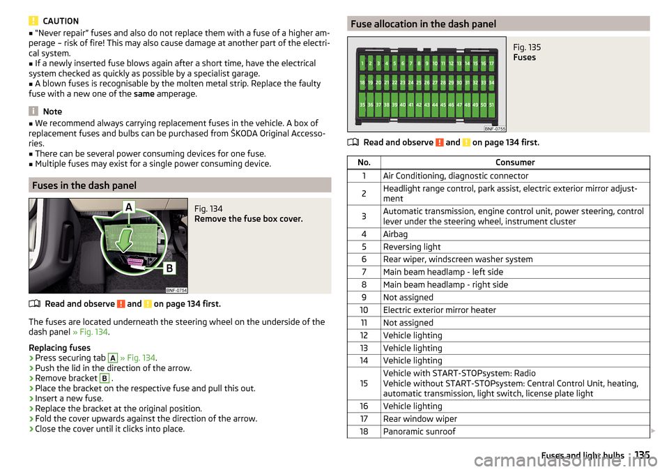
Fuse allocation in the dash panelFig. 135
Fuses
Read and observe and on page 134 first.
No.Consumer1Air Conditioning, diagnostic connector2Headlight range control, park assist, electric exterior mirror adjust-
ment3Automatic transmission, engine control unit, power steering, control
lever under the steering wheel, instrument cluster4Airbag5Reversing light6Rear wiper, windscreen washer system7Main beam headlamp - left side8Main beam headlamp - right side9Not assigned10Electric exterior mirror heater11Not assigned12Vehicle lighting13Vehicle lighting14Vehicle lighting15Vehicle with START-STOPsystem: Radio
Vehicle without START-STOPsystem: Central Control Unit, heating,
automatic transmission, light switch, license plate light16Vehicle lighting17Rear window wiper18Panoramic sunroof 135Fuses and light bulbs
Page 139 of 160
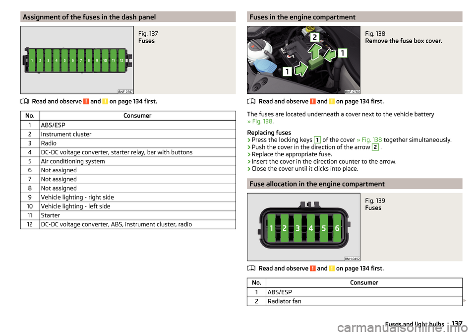
Assignment of the fuses in the dash panelFig. 137
Fuses
Read and observe and on page 134 first.
No.Consumer1ABS/ESP2Instrument cluster3Radio4DC-DC voltage converter, starter relay, bar with buttons5Air conditioning system6Not assigned7Not assigned8Not assigned9Vehicle lighting - right side10Vehicle lighting - left side11Starter12DC-DC voltage converter, ABS, instrument cluster, radioFuses in the engine compartmentFig. 138
Remove the fuse box cover.
Read and observe and on page 134 first.
The fuses are located underneath a cover next to the vehicle battery
» Fig. 138 .
Replacing fuses
›
Press the locking keys
1
of the cover » Fig. 138 together simultaneously.
›
Push the cover in the direction of the arrow
2
.
›
Replace the appropriate fuse.
›
Insert the cover in the direction counter to the arrow.
›
Close the cover until it clicks into place.
Fuse allocation in the engine compartment
Fig. 139
Fuses
Read and observe and on page 134 first.
No.Consumer1ABS/ESP2Radiator fan 137Fuses and light bulbs
Page 140 of 160
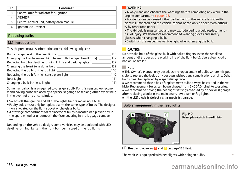
No.Consumer3Control unit for radiator fan, ignition4ABS/ESP5Central control unit, battery data module6Ignition lock, starter
Replacing bulbs
Introduction
This chapter contains information on the following subjects:
Bulb arrangement in the headlights
138
Changing the low beam and high beam bulb (halogen headlights)
139
Replacing bulb for daytime running lights and parking lights
139
Changing the front turn signal bulb
139
Replacing the bulb for the fog light
140
Replacing the bulb for the licence plate light
140
Rear Light
141
Changing a bulb in the tail light
141
Some manual skills are required to change a bulb. For this reason, we recom-
mend having bulbs replaced by a specialist garage or seeking other expert help
in the event of any uncertainties.
▶ Switch off the ignition and all of the lights before replacing a bulb.
▶ Faulty bulbs must only be replaced with the same type of bulbs. The designa-
tion is located on the light socket or the glass bulb.
▶ A stowage compartment for replacement bulbs is located in a plastic box in
the spare wheel or underneath the floor covering in the luggage compart-
ment.
Depending on the vehicle design, some vehicles may be equipped with LED
daytime running lights in the front bumper instead of the fog lights.
WARNING■ Always read and observe the warnings before completing any work in the
engine compartment » page 106.■
Accidents can be caused if the road in front of the vehicle is not suffi-
ciently illuminated and the vehicle cannot or can only be seen with difficul-
ty by other road users.
■
The H4 bulb is pressurised and may explode during a bulb replacement -
risk of injury! We therefore recommended wearing gloves and safety
glasses when changing a bulb.
■
Switch off the respective vehicle light when changing the bulb.
CAUTION
Do not take hold of the glass bulb with naked fingers (even the smallest
amount of dirt reduces the working life of the light bulb). Use a clean cloth,
napkin, or similar.
Note
■ This Owner's Manual only describes the replacement of bulbs where it is pos-
sible to replace the bulbs on your own without any complications arising. Other
bulbs must be replaced by a specialist garage.■
We recommend that a box of replacement bulbs always be carried in the ve-
hicle. Replacement bulbs can be purchased from ŠKODAOriginal Accessories.
■
We recommend having the headlight settings checked by a specialist garage
after replacing a bulb in the main beam, low beam or fog lights.
■
If the LED diode is defect visit a specialist garage.
Bulb arrangement in the headlights
Fig. 140
Principle sketch: Headlights
Read and observe and on page 138 first.
The vehicle is equipped with headlights with halogen bulbs.
138Do-it-yourself
Page 141 of 160
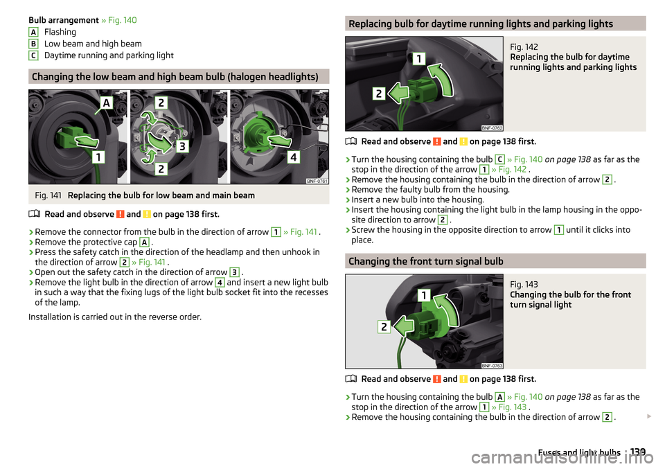
Bulb arrangement » Fig. 140
Flashing
Low beam and high beam
Daytime running and parking light
Changing the low beam and high beam bulb (halogen headlights)
Fig. 141
Replacing the bulb for low beam and main beam
Read and observe
and on page 138 first.
›
Remove the connector from the bulb in the direction of arrow
1
» Fig. 141 .
›
Remove the protective cap
A
.
›
Press the safety catch in the direction of the headlamp and then unhook in
the direction of arrow
2
» Fig. 141 .
›
Open out the safety catch in the direction of arrow
3
.
›
Remove the light bulb in the direction of arrow
4
and insert a new light bulb
in such a way that the fixing lugs of the light bulb socket fit into the recesses
of the lamp.
Installation is carried out in the reverse order.
ABCReplacing bulb for daytime running lights and parking lightsFig. 142
Replacing the bulb for daytime
running lights and parking lights
Read and observe and on page 138 first.
›
Turn the housing containing the bulb
C
» Fig. 140 on page 138 as far as the
stop in the direction of the arrow
1
» Fig. 142 .
›
Remove the housing containing the bulb in the direction of arrow
2
.
›
Remove the faulty bulb from the housing.
›
Insert a new bulb into the housing.
›
Insert the housing containing the light bulb in the lamp housing in the oppo-
site direction to arrow
2
.
›
Screw the housing in the opposite direction to arrow
1
until it clicks into
place.
Changing the front turn signal bulb
Fig. 143
Changing the bulb for the front
turn signal light
Read and observe and on page 138 first.
›
Turn the housing containing the bulb
A
» Fig. 140 on page 138 as far as the
stop in the direction of the arrow
1
» Fig. 143 .
›
Remove the housing containing the bulb in the direction of arrow
2
.
139Fuses and light bulbs
Page 142 of 160
›Unscrew the defective bulb in its housing in an
anti-clockwise direction and
remove it.›
Place a new bulb in the housing and turn it in a clockwise direction as far as
it will go.
›
Insert the housing containing the light bulb in the lamp housing in the oppo-
site direction to arrow
2
.
›
Screw the housing in the opposite direction to arrow
1
until it clicks into
place.
Replacing the bulb for the fog light
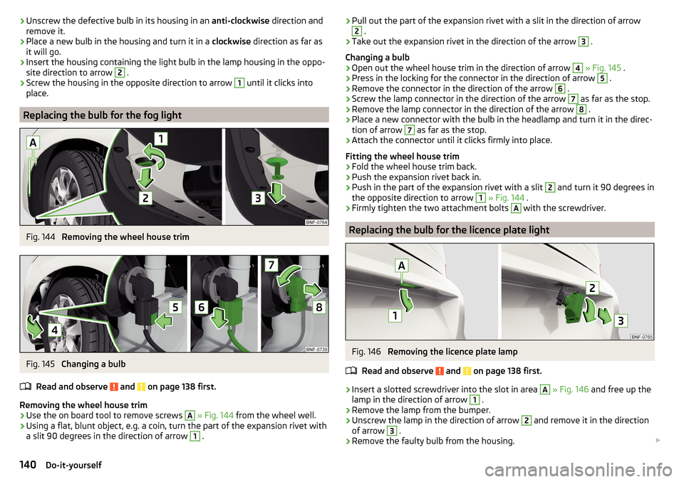
Fig. 144
Removing the wheel house trim
Fig. 145
Changing a bulb
Read and observe
and on page 138 first.
Removing the wheel house trim
›
Use the on board tool to remove screws
A
» Fig. 144 from the wheel well.
›
Using a flat, blunt object, e.g. a coin, turn the part of the expansion rivet with
a slit 90 degrees in the direction of arrow
1
.
› Pull out the part of the expansion rivet with a slit in the direction of arrow2 .›
Take out the expansion rivet in the direction of the arrow
3
.
Changing a bulb
›
Open out the wheel house trim in the direction of arrow
4
» Fig. 145 .
›
Press in the locking for the connector in the direction of arrow
5
.
›
Remove the connector in the direction of the arrow
6
.
›
Screw the lamp connector in the direction of the arrow
7
as far as the stop.
›
Remove the lamp connector in the direction of the arrow
8
.
›
Place a new connector with the bulb in the headlamp and turn it in the direc-
tion of arrow
7
as far as the stop.
›
Attach the connector until it clicks firmly into place.
Fitting the wheel house trim
›
Fold the wheel house trim back.
›
Push the expansion rivet back in.
›
Push in the part of the expansion rivet with a slit
2
and turn it 90 degrees in
the opposite direction to arrow
1
» Fig. 144 .
›
Firmly tighten the two attachment bolts
A
with the screwdriver.
Replacing the bulb for the licence plate light
Fig. 146
Removing the licence plate lamp
Read and observe
and on page 138 first.
›
Insert a slotted screwdriver into the slot in area
A
» Fig. 146 and free up the
lamp in the direction of arrow
1
.
›
Remove the lamp from the bumper.
›
Unscrew the lamp in the direction of arrow
2
and remove it in the direction
of arrow
3
.
›
Remove the faulty bulb from the housing.
140Do-it-yourself
Page 143 of 160
›Insert a new bulb into the housing.›Insert the housing with the bulb in the lamp and turn it in the opposite direc-
tion to arrow 2
as far as the stop.
›
Insert the lamp into area
A
into the bumper opening and press lightly until
the spring locks into place.
CAUTION
Ensure that the vehicle paintwork and the tail lamp are not damaged when re-
moving and installing the tail lamp.
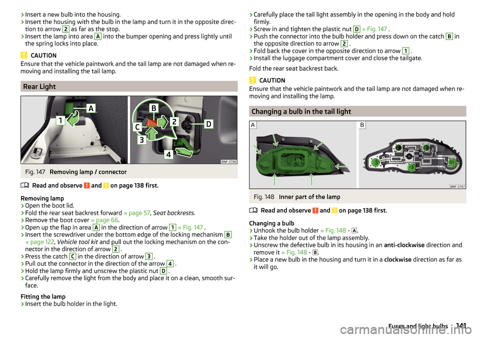
Rear Light
Fig. 147
Removing lamp / connector
Read and observe
and on page 138 first.
Removing lamp
›
Open the boot lid.
›
Fold the rear seat backrest forward » page 57, Seat backrests .
›
Remove the boot cover » page 66.
›
Open up the flap in area
A
in the direction of arrow
1
» Fig. 147 .
›
Insert the screwdriver under the bottom edge of the locking mechanism
B
» page 122 , Vehicle tool kit and pull out the locking mechanism on the con-
nector in the direction of arrow
2
.
›
Press the catch
C
in the direction of arrow
3
.
›
Pull out the connector in the direction of the arrow
4
.
›
Hold the lamp firmly and unscrew the plastic nut
D
.
›
Carefully remove the light from the body and place it on a clean, smooth sur-
face.
Fitting the lamp
›
Insert the bulb holder in the light.
› Carefully place the tail light assembly in the opening in the body and hold
firmly.›
Screw in and tighten the plastic nut
D
» Fig. 147 .
›
Push the connector into the bulb holder and press down on the catch
B
in
the opposite direction to arrow
2
.
›
Fold back the cover in the opposite direction to arrow
1
.
›
Install the luggage compartment cover and close the tailgate.
Fold the rear seat backrest back.
CAUTION
Ensure that the vehicle paintwork and the tail lamp are not damaged when re-
moving and installing the lamp.
Changing a bulb in the tail light
Fig. 148
Inner part of the lamp
Read and observe
and on page 138 first.
Changing a bulb
›
Unhook the bulb holder » Fig. 148 -
.
›
Take the holder out of the lamp assembly.
›
Unscrew the defective bulb in its housing in an anti-clockwise direction and
remove it » Fig. 148 -
.
›
Place a new bulb in the housing and turn it in a clockwise direction as far as
it will go.
141Fuses and light bulbs
Page 150 of 160
Central locking button40
Change engine oil
109
Change engine oil
109
Changing Bulb in the tail light
141
Front turn signal bulb139
light bulb in tail light141
Low beam and high beam bulb - halogen head- lights
139
Wheels123
Changing a wheel Follow-up work
126
Preliminary work123
Changing wheels Wheel removal and fix
126
Charging a vehicle battery114
Checking Battery electrolyte level
114
Brake fluid112
Coolant111
Engine oil109
Oil level109
Windscreen washer fluid108
Checks Statutory checks
92
Children and safety19
Child safety Side airbag
21
Child safety lock42
Child seat Classification
21
ISOFIX22
on the front passenger seat20
TOP TETHER24
Use of child seats22
Use of ISOFIX child seats23
Chrome parts Refer to vehicle maintenance
98
Cigarette lighter60
City Safe Drive89
Disable/Enable90
Operation89
warning symbol38
Clean Anodized parts
98
Chrome parts98
Cleaning Alcantara
101
and maintaining belts102
artificial leather101
headlight glasses98
materials101
natural leather100
plastic parts98
seats covers of the electrically heated seats101
wheels99
Cleaning safety belt
102
Cleaning seat covers
101
Cleaning the interior artificial leather
101
Seat covers101
Cleaning the vehicle exterior Cavity protection
99
Decorative films97
Door locking cylinder99
Headlight glasses98
Protective films97
Under-body protection99
Vehicle paintwork97
wheels99
Windows and external mirrors98
Cleaning vehicle95
Cleaning vehicle exterior96
Anodized parts98
Chrome parts98
Plastic parts98
Rubber seals98
Wiper blades100
Clean interior Safety belt
102
Clothes hook63
CNG105
Fuel reserve display29
refuelling104
Refuelling104
Sticker105
Cockpit 12-Volt power outlet
61
Ashtray61
Cigarette lighter60
General view27
Light50
storage compartments58
useful equipment58
compartments58
Components of the puncture repair kits127
Compressed natural gas see CNG
105
Computer see multi-function display
31
Conserving the vehicle paintwork see vehicle care
97
convenience turn signal48
Coolant110
Checking111
Replenishing111
Warning light35
Correct routing of seat belt
12
Correct seated position8
Front passenger10
Rear seats10
Correct seat position Driver
9
Counter for distance driven30
148Index