heater SKODA CITIGO 2015 1.G Owner's Manual
[x] Cancel search | Manufacturer: SKODA, Model Year: 2015, Model line: CITIGO, Model: SKODA CITIGO 2015 1.GPages: 160, PDF Size: 23.1 MB
Page 29 of 160
Using the system
Cockpit
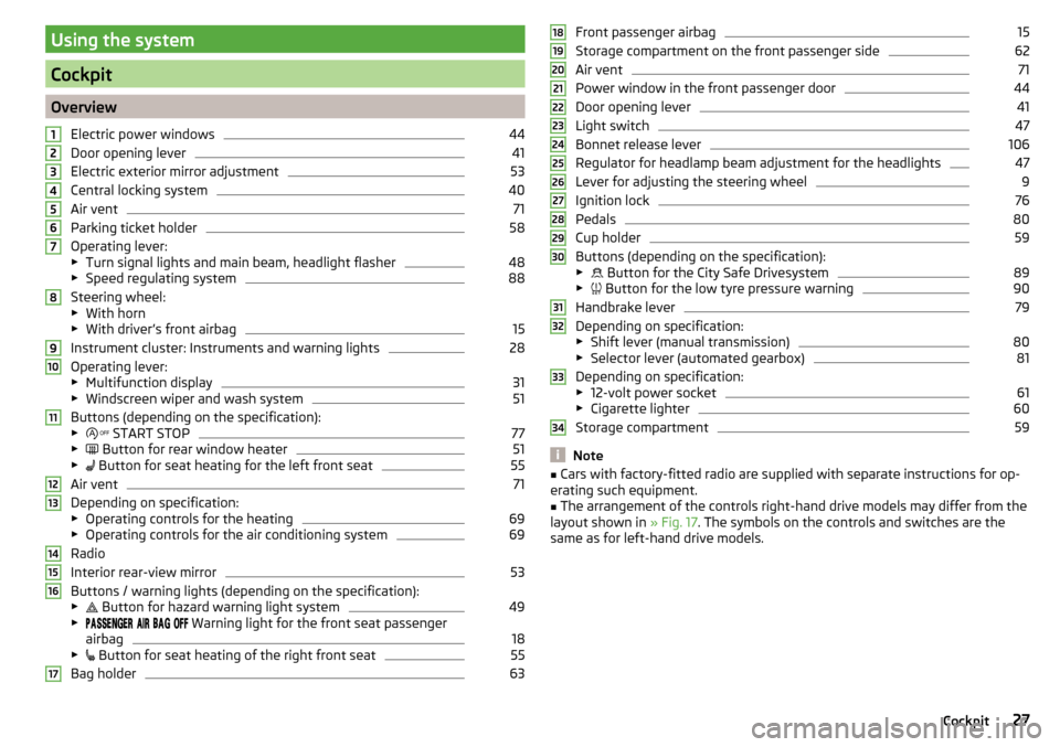
OverviewElectric power windows
44
Door opening lever
41
Electric exterior mirror adjustment
53
Central locking system
40
Air vent
71
Parking ticket holder
58
Operating lever:
▶ Turn signal lights and main beam, headlight flasher
48
▶Speed regulating system
88
Steering wheel:
▶ With horn
▶ With driver’s front airbag
15
Instrument cluster: Instruments and warning lights
28
Operating lever:
▶ Multifunction display
31
▶Windscreen wiper and wash system
51
Buttons (depending on the specification):
▶ START STOP
77
▶
Button for rear window heater
51
▶
Button for seat heating for the left front seat
55
Air vent
71
Depending on specification:
▶ Operating controls for the heating
69
▶Operating controls for the air conditioning system
69
Radio
Interior rear-view mirror
53
Buttons / warning lights (depending on the specification):
▶ Button for hazard warning light system
49
▶
Warning light for the front seat passenger
airbag
18
▶ Button for seat heating of the right front seat
55
Bag holder
631234567891011121314151617Front passenger airbag15
Storage compartment on the front passenger side
62
Air vent
71
Power window in the front passenger door
44
Door opening lever
41
Light switch
47
Bonnet release lever
106
Regulator for headlamp beam adjustment for the headlights
47
Lever for adjusting the steering wheel
9
Ignition lock
76
Pedals
80
Cup holder
59
Buttons (depending on the specification):
▶ Button for the City Safe Drivesystem
89
▶
Button for the low tyre pressure warning
90
Handbrake lever
79
Depending on specification:
▶ Shift lever (manual transmission)
80
▶Selector lever (automated gearbox)
81
Depending on specification:
▶ 12-volt power socket
61
▶Cigarette lighter
60
Storage compartment
59
Note
■Cars with factory-fitted radio are supplied with separate instructions for op-
erating such equipment.■
The arrangement of the controls right-hand drive models may differ from the
layout shown in » Fig. 17. The symbols on the controls and switches are the
same as for left-hand drive models.
181920212223242526272829303132333427Cockpit
Page 52 of 160
Switching on the side light on both sides›Turn the light switch » Fig. 42 on page 49 to position and lock the vehicle.
After pulling out the ignition key and opening the driver's door, an audible
warning sounds. After a few seconds or after closing the driver's door, the au-
dible alarm is turned off, but the parking lights will remain switched on.
CAUTION
Turning on the parking light means the battery is heavily loaded.
Driving abroad
Read and observe
on page 47 first.
When driving in countries with opposing traffic system (traffic on the
left/right), your headlights may dazzle oncoming traffic. In order to avoid this,
the headlights must be adjusted at a specialist garage.
Indoor Lighting
Introduction
This chapter contains information on the following subjects:
Interior light
50
With the ignition off, the light turns off automatically after about 10 minutes.
Interior light
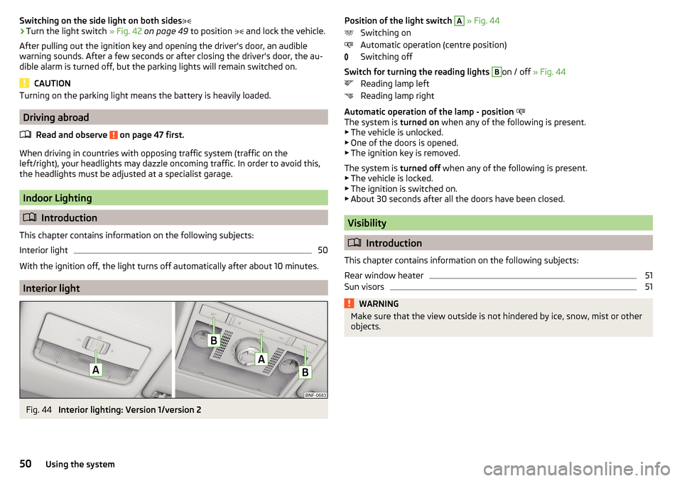
Fig. 44
Interior lighting: Version 1/version 2
Position of the light switch A » Fig. 44
Switching on
Automatic operation (centre position)
Switching off
Switch for turning the reading lights B
on / off » Fig. 44
Reading lamp left
Reading lamp right
Automatic operation of the lamp - position
The system is turned on when any of the following is present.
▶ The vehicle is unlocked.
▶ One of the doors is opened.
▶ The ignition key is removed.
The system is turned off when any of the following is present.
▶ The vehicle is locked.
▶ The ignition is switched on.
▶ About 30 seconds after all the doors have been closed.
Visibility
Introduction
This chapter contains information on the following subjects:
Rear window heater
51
Sun visors
51WARNINGMake sure that the view outside is not hindered by ice, snow, mist or other
objects.50Using the system
Page 53 of 160
Rear window heaterFig. 45
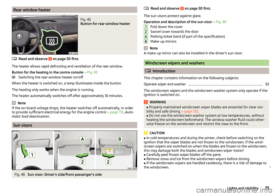
Button for rear window heater
Read and observe on page 50 first.
The heater allows rapid defrosting and ventilation of the rear window.
Button for the heating in the centre console » Fig. 45
Switching the rear window heater on/off
When the heater is switched on, a lamp illuminates inside the button.
The heating only works when the engine is running.
The heater automatically switches off after approximately 10 minutes.
Note
If the on-board voltage drops, the heater switches off automatically, in order
to provide sufficient electrical energy for the engine control » page 115, Auto-
matic load deactivation .
Sun visors
Fig. 46
Sun visor: Driver's side/front passenger's side
Read and observe on page 50 first.
The sun visors protect against glare.
Operation and description of the sun visor » Fig. 46
Fold down the cover
Swivel cover towards the door
Parking ticket band (if part of the specification)
Make-up mirrors
Note
A make-up mirror can also be installed in the driver's sun visor.
Windscreen wipers and washers
Introduction
This chapter contains information on the following subjects:
Operate wiper and washer
52
The windscreen wipers and the windscreen washer system only operate if the
ignition is switched on.
WARNING■ Properly maintained windscreen wiper blades are essential for clear visi-
bility and safe driving » page 133.■
Do not use the windscreen washer system at low temperatures, without
heating the windscreen beforehand. The window washer fluid could other-
wise freeze on the windscreen and restrict the view to the front.
CAUTION
■ In cold temperatures and during the winter, check before switching on the
ignition that the wiper blades are not frozen to the windscreen. If the wind-
screen wipers are switched on when the blades are frozen to the windscreen,
this may damage both the blades and windscreen wiper motor!■
Carefully peel frozen wiper blades off the pane.
■
Remove snow and ice from the windscreen wipers before driving.
■
If the windscreen wipers are handled carelessly, there is a risk of damage to
the windscreen.
12AB51Lights and visibility
Page 55 of 160
Interior mirror dimmingFig. 48
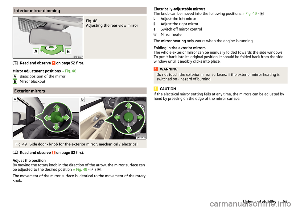
Adjusting the rear view mirror
Read and observe on page 52 first.
Mirror adjustment positions » Fig. 48
Basic position of the mirror
Mirror blackout
Exterior mirrors
Fig. 49
Side door - knob for the exterior mirror: mechanical / electrical
Read and observe
on page 52 first.
Adjust the position
By moving the rotary knob in the direction of the arrow, the mirror surface can
be adjusted to the desired position » Fig. 49 -
/
.
The movement of the mirror surface is identical to the movement of the rotary
knob.
ABElectrically-adjustable mirrors
The knob can be moved into the following positions » Fig. 49 - .
Adjust the left mirror
Adjust the right mirror
Switch off mirror control
Mirror heater
The mirror heating only works when the engine is running.
Folding in the exterior mirrors
The whole exterior mirror can be manually folded towards the side windows.
To put it back into its original position, it should be folded back from the side
window until it audibly clicks into place.WARNINGDo not touch the exterior mirror surfaces, if the exterior mirror heating is
switched on - hazard of burning.
CAUTION
If the electrical mirror setting fails at any time, the mirrors can be adjusted by
hand by pressing on the edge of the mirror surface.53Lights and visibility
Page 67 of 160
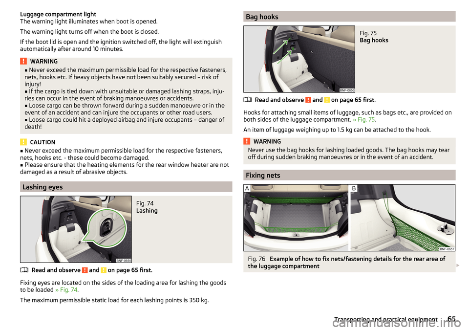
Luggage compartment light
The warning light illuminates when boot is opened.
The warning light turns off when the boot is closed.
If the boot lid is open and the ignition switched off, the light will extinguish
automatically after around 10 minutes.WARNING■ Never exceed the maximum permissible load for the respective fasteners,
nets, hooks etc. If heavy objects have not been suitably secured – risk of
injury!■
If the cargo is tied down with unsuitable or damaged lashing straps, inju-
ries can occur in the event of braking manoeuvres or accidents.
■
Loose cargo can be thrown forward during a sudden manoeuvre or in the
event of an accident and can injure the occupants or other road users.
■
Loose cargo could hit a deployed airbag and injure occupants – danger of
death!
CAUTION
■ Never exceed the maximum permissible load for the respective fasteners,
nets, hooks etc. - these could become damaged.■
Please ensure that the heating elements for the rear window heater are not
damaged as a result of abrasive objects.
Lashing eyes
Fig. 74
Lashing
Read and observe and on page 65 first.
Fixing eyes are located on the sides of the loading area for lashing the goods to be loaded » Fig. 74.
The maximum permissible static load for each lashing points is 350 kg.
Bag hooksFig. 75
Bag hooks
Read and observe and on page 65 first.
Hooks for attaching small items of luggage, such as bags etc., are provided on
both sides of the luggage compartment. » Fig. 75.
An item of luggage weighing up to 1.5 kg can be attached to the hook.
WARNINGNever use the bag hooks for lashing loaded goods. The bag hooks may tear
off during sudden braking manoeuvres or in the event of an accident.
Fixing nets
Fig. 76
Example of how to fix nets/fastening details for the rear area of
the luggage compartment
65Transporting and practical equipment
Page 73 of 160
Air outlet ventsFig. 85
Air outlet vents
Read and observe
and on page 69 first.
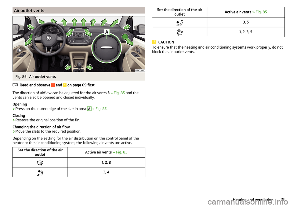
The direction of airflow can be adjusted for the air vents 3 » Fig. 85 and the
vents can also be opened and closed individually.
Opening
›
Press on the outer edge of the slat in area
A
» Fig. 85 .
Closing
›
Restore the original position of the fin.
Changing the direction of air flow
›
Move the slats to the required position.
Depending on the setting for the air distribution on the control panel of the
heater or the air conditioning system, the following air vents are active.
Set the direction of the air outletActive air vents » Fig. 851, 2 , 33 , 4Set the direction of the air
outletActive air vents » Fig. 853, 51, 2 , 3 , 5
CAUTION
To ensure that the heating and air conditioning systems work properly, do not
block the air outlet vents.71Heating and ventilation
Page 103 of 160
■Some clothing materials, e.g. dark denim, do not have sufficient colour fast-
ness. This can cause damage or clearly visible discolouration to seat covers,
even when used correctly. This applies particularly to light-coloured seat cov-
ers. This does not relate to a fault in the seat cover, but rather to poor colour
fastness of the clothing textiles.■
Sharp-edged objects on items of clothing such as zip fasteners, rivets, sharp-
edged belts etc may leave permanent scratches or signs of rubbing on the sur-
face or damage these. Such damage cannot be subsequently recognised as a
justified complaint.
Note
When using the vehicle, minor visible changes may occur to the leather parts
of the covers (e.g. wrinkles or creases) as a result of the stress applied to the
covers.
Artificial leather, materials and Alcantara ®
Read and observe
and on page 100 first.
Artificial leather
Clean artificial leather with a damp cloth.
If this method does not completely clean the artificial leather, use a mild soap solution or cleaning products specially designed for this purpose.
Fabric
Clean upholstery cover materials and cloth trims on doors, luggage compart-
ment cover, etc. using specific cleaning agents, e.g., dry foam.
Use a soft sponge, brush, or commercially available microfibre cloth.
Use a cloth and a specific cleaning agent to clean the roof trim.
Remove any lumps on the cover fabric and any fabric residue using a brush.
Remove stubborn hair using a “cleaning glove”.
Alcantara ®
Dust and dirt in pores, creases and seams may chafe and damage the surface.
Therefore, they must be removed regularly at short intervals with a cloth or
vacuum cleaner.
Minor changes in colour caused by use are normal.
CAUTION■ For Alcantara ®
seat covers, do not use any solvents, floor wax, shoe cream,
stain remover, leather cleaners or similar agents.■
Avoid leaving the vehicle in bright sunlight for long periods of time in order
to stop the artificial leather, materials or Alcantara ®
from bleaching. During ex-
tended periods of standing outdoors, protect artificial leather, fabrics or Alcan-
tara ®
by covering.
■
Some clothing materials, e.g. dark denim, do not have sufficient colour fast-
ness. This can cause damage or clearly visible discolouration to seat covers,
even when used correctly. This applies particularly to light-coloured seat cov-
ers. This does not relate to a fault in the seat cover, but rather to poor colour
fastness of the clothing textiles.
Seat covers
Read and observe
and on page 100 first.
Electrically heated seats
Use a specific cleaning agent such as dry foam or similar to clean the covers. »
.
Seats without seat heating
Thoroughly vacuum the seat covers with a vacuum cleaner before cleaning.
Clean the seat covers with a damp cloth or cleaning products specially de-
signed for this purpose.
Indented points arising on the fabrics by everyday use, can be removed by
brushing against the direction of hair with a damp brush.
Always clean all parts of the covers, so that there are no visible edges. Then
allow the seat to dry completely.
CAUTION
■ Do not clean the covers of electrically heated seats either with water or with
other liquids - there is a risk of damaging the seat heating system.■
Regularly remove dust from the seat covers using a vacuum cleaner.
■
Electrically heated seats must not be dried after cleaning by switching on the
heater.
■
Do not sit on wet seats - risk of seat deformation.
■
Always clean the seats “from seam to seam”.
101Care and maintenance
Page 117 of 160
WARNING■When you charge a battery, hydrogen is released, and a highly explosive
gas mixture is also produced. An explosion can be caused through sparkling
over during unclamping or loosening of the cable plug while the ignition is
on.■
Creating a bridge between the poles on the battery (e.g. with metal ob-
jects - cables) creates a short circuit - risk of damage to the battery, explo-
sion and burning of the battery, jets of acid spurting out.
■
Avoid creating sparks when working with cables and electrical devices.
Strong sparking represents a risk of injury.
■
Before carrying out any work on the electrical system, switch off the en-
gine, the ignition and all electrical consumers and disconnect the negative
terminal
.
■
“Quick-charging” the vehicle battery is dangerous and requires a special
charger and specialist knowledge.
■
We therefore recommend that vehicle batteries be “rapidly charged” by a
specialist garage.
CAUTION
On vehicles with the START-STOP system, the pole terminal of the charger
must not be connected directly to the negative terminal of the vehicle battery,
but only to the engine earth » page 129.
Replace
Read and observe
and on page 113 first.
The new vehicle battery must have the same capacity, voltage, current and
size as the original battery. Suitable vehicle battery types can be purchased
from a specialist garage.
We recommend you have the battery replaced by a specialist garage.
Disconnecting and reconnecting
Read and observe
and on page 113 first.
Disconnecting
›
Switch off the ignition.
›
Disconnect the negative terminal
first and then the positive
terminal of
the battery.
Connecting›Connect the positive terminal first, then the negative battery terminal.
After disconnecting and re-connecting the vehicle battery, the following func-
tions or devices are partially or completely inoperative.Function / deviceOperating measureRadioEnter code » Owner´s Manual
RadioTime settings» page 33
CAUTION
■ Disconnect the vehicle battery only with the ignition turned off - there is a
risk of damaging the electrical system of the vehicle.■
Under no circumstances must the battery cables be connected incorrectly –
risk of a cable fire.
Note
■ After disconnecting and re-connecting the vehicle battery, we recommend
having the vehicle checked by a specialist to ensure that the full functionality
of all electrical systems is guaranteed.■
The data of the multi-function display will be reset.
Automatic load deactivation
Read and observe
and on page 113 first.
The vehicle's electrical system automatically prevents the battery from dis-
charging when the battery is being heavily used. This manifests itself by the
following. ▶ The idling speed is raised to allow the generator to deliver more electricity to
the electrical system.
▶ Where necessary, large convenience consumers such as seat heaters and
rear window heaters have their power limited or are shut off completely in
the event of an emergency.
115Inspecting and replenishing
Page 137 of 160
CAUTION■“Never repair” fuses and also do not replace them with a fuse of a higher am-
perage – risk of fire! This may also cause damage at another part of the electri-
cal system.■
If a newly inserted fuse blows again after a short time, have the electrical
system checked as quickly as possible by a specialist garage.
■
A blown fuses is recognisable by the molten metal strip. Replace the faulty
fuse with a new one of the same amperage.
Note
■
We recommend always carrying replacement fuses in the vehicle. A box of
replacement fuses and bulbs can be purchased from ŠKODA Original Accesso-
ries.■
There can be several power consuming devices for one fuse.
■
Multiple fuses may exist for a single power consuming device.
Fuses in the dash panel
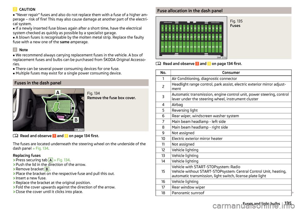
Fig. 134
Remove the fuse box cover.
Read and observe and on page 134 first.
The fuses are located underneath the steering wheel on the underside of the dash panel » Fig. 134.
Replacing fuses
›
Press securing tab
A
» Fig. 134 .
›
Push the lid in the direction of the arrow.
›
Remove bracket
B
.
›
Place the bracket on the respective fuse and pull this out.
›
Insert a new fuse.
›
Replace the bracket at the original position.
›
Fold the cover upwards against the direction of the arrow.
›
Close the cover until it clicks into place.
Fuse allocation in the dash panelFig. 135
Fuses
Read and observe and on page 134 first.
No.Consumer1Air Conditioning, diagnostic connector2Headlight range control, park assist, electric exterior mirror adjust-
ment3Automatic transmission, engine control unit, power steering, control
lever under the steering wheel, instrument cluster4Airbag5Reversing light6Rear wiper, windscreen washer system7Main beam headlamp - left side8Main beam headlamp - right side9Not assigned10Electric exterior mirror heater11Not assigned12Vehicle lighting13Vehicle lighting14Vehicle lighting15Vehicle with START-STOPsystem: Radio
Vehicle without START-STOPsystem: Central Control Unit, heating,
automatic transmission, light switch, license plate light16Vehicle lighting17Rear window wiper18Panoramic sunroof 135Fuses and light bulbs
Page 138 of 160
No.Consumer19Central locking system20Rear window heater21Reversing light22Horn23Voltage transformer24Headlamp flasher25Windscreen wipers26Radio27Turn signal lights, brake lights28Selector lever for the automatic transmission29Fuel pump30Engine control unit, instrument cluster, central control unit, rain sen-
sor, control lever under the steering wheel, diagnostic connector31Vehicle lighting32Central control unit33Vehicle lighting34Indoor lighting35Vehicle lighting36Vehicle lighting37ESC38Key bar39Lever under the steering wheel, windscreen washer system40Engine components41Brake pedal switch, cooling fan42Engine control unit43Fuel pump44Engine components45Engine components4612-volt power socket47Air blower for air conditioning/heating48Seat heaters49Electric power windowsNo.Consumer50Vehicle lighting51Electric power windows
Fuses in the dash panel
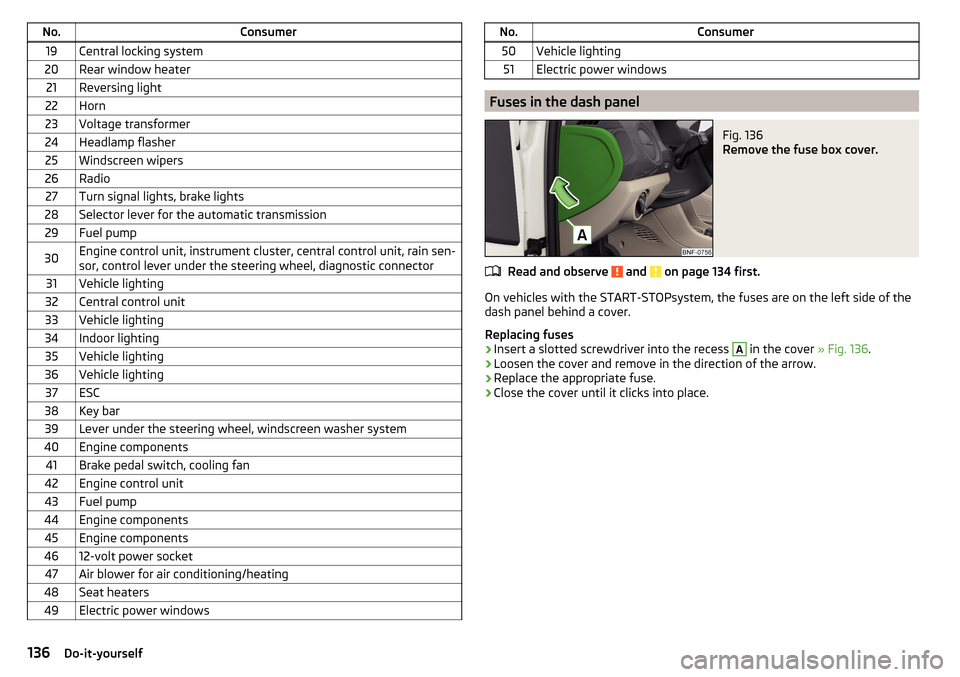
Fig. 136
Remove the fuse box cover.
Read and observe and on page 134 first.
On vehicles with the START-STOPsystem, the fuses are on the left side of the
dash panel behind a cover.
Replacing fuses
›
Insert a slotted screwdriver into the recess
A
in the cover » Fig. 136.
›
Loosen the cover and remove in the direction of the arrow.
›
Replace the appropriate fuse.
›
Close the cover until it clicks into place.
136Do-it-yourself