check engine light SKODA CITIGO 2016 1.G User Guide
[x] Cancel search | Manufacturer: SKODA, Model Year: 2016, Model line: CITIGO, Model: SKODA CITIGO 2016 1.GPages: 172, PDF Size: 24.59 MB
Page 126 of 172
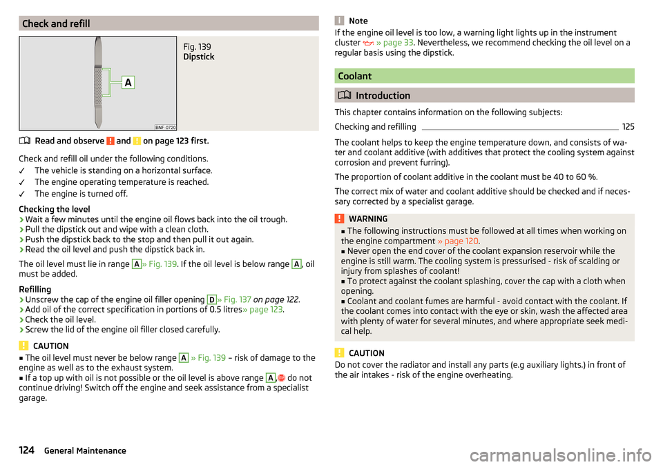
Check and refillFig. 139
Dipstick
Read and observe and on page 123 first.
Check and refill oil under the following conditions.The vehicle is standing on a horizontal surface.
The engine operating temperature is reached.
The engine is turned off.
Checking the level
›
Wait a few minutes until the engine oil flows back into the oil trough.
›
Pull the dipstick out and wipe with a clean cloth.
›
Push the dipstick back to the stop and then pull it out again.
›
Read the oil level and push the dipstick back in.
The oil level must lie in range
A
» Fig. 139 . If the oil level is below range
A
, oil
must be added.
Refilling
›
Unscrew the cap of the engine oil filler opening
D
» Fig. 137 on page 122 .
›
Add oil of the correct specification in portions of 0.5 litres
» page 123.
›
Check the oil level.
›
Screw the lid of the engine oil filler closed carefully.
CAUTION
■
The oil level must never be below range A » Fig. 139 – risk of damage to the
engine as well as to the exhaust system.■
If a top up with oil is not possible or the oil level is above range
A
,
do not
continue driving! Switch off the engine and seek assistance from a specialist
garage.
NoteIf the engine oil level is too low, a warning light lights up in the instrument
cluster » page 33 . Nevertheless, we recommend checking the oil level on a
regular basis using the dipstick.
Coolant
Introduction
This chapter contains information on the following subjects:
Checking and refilling
125
The coolant helps to keep the engine temperature down, and consists of wa-
ter and coolant additive (with additives that protect the cooling system against
corrosion and prevent furring).
The proportion of coolant additive in the coolant must be 40 to 60 %.
The correct mix of water and coolant additive should be checked and if neces-
sary corrected by a specialist garage.
WARNING■ The following instructions must be followed at all times when working on
the engine compartment » page 120.■
Never open the end cover of the coolant expansion reservoir while the
engine is still warm. The cooling system is pressurised - risk of scalding or
injury from splashes of coolant!
■
To protect against the coolant splashing, cover the cap with a cloth when
opening.
■
Coolant and coolant fumes are harmful - avoid contact with the coolant. If
the coolant comes into contact with the eye or skin, wash the affected area
with plenty of water for several minutes, and where appropriate seek medi-
cal help.
CAUTION
Do not cover the radiator and install any parts (e.g auxiliary lights.) in front of
the air intakes - risk of the engine overheating.124General Maintenance
Page 127 of 172
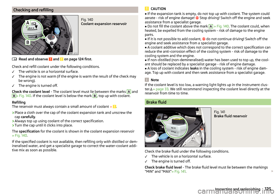
Checking and refillingFig. 140
Coolant expansion reservoir
Read and observe and on page 124 first.
Check and refill coolant under the following conditions.The vehicle is on a horizontal surface.
The engine is not warm (if the engine is warm the result of the check may
be wrong).
The engine is turned off.
Check the coolant level - The coolant level must lie between the marks
A
and
B
» Fig. 140. If the coolant level is below the mark
B
, top up with coolant.
Refilling
The reservoir must always contain a small amount of coolant »
.
›
Place a cloth over the cap of the coolant expansion tank and unscrew the
cap carefully .
›
Always top up using coolant of the correct specification.
›
Turn the cap until it clicks into place.
The specification for the coolant is shown in the coolant expansion reservoir
» Fig. 140 .
If the specified coolant is not available, then refilling only with distilled or dem-
ineralised water, and get a specialist garage to correct the water-coolant addi-
tive mix as soon as possible.
CAUTION■ If the expansion tank is empty, do not top up with coolant. The system could
aerate - risk of engine damage! Stop driving! Switch off the engine and seek
assistance from a specialist garage.■
Do not fill the coolant above the mark
A
» Fig. 140 . The coolant could, when
heated, be expelled from the cooling system - risk of damage to the engine
parts.
■
If it is not possible to add coolant,
do not continue driving! Switch off the
engine and seek assistance from a specialist garage.
■
A coolant additive which does not correspond to the correct specification can
reduce the anti-corrosion effect of the cooling system - risk of damage to the
cooling system and the engine.
■
If non-distilled (non-demineralised) water has been used to top up, the cool-
ant should be replaced by a specialist garage - risk of engine damage.
■
A loss of coolant indicates leaks in the cooling system - risk of engine dam-
age. Top up with coolant and then seek assistance from a specialist garage.
Note
If the coolant level is too low, a warning light lights up in the instrument clus-
ter » page 33 . We still recommend inspecting the coolant level directly at the
reservoir from time to time.
Brake fluid
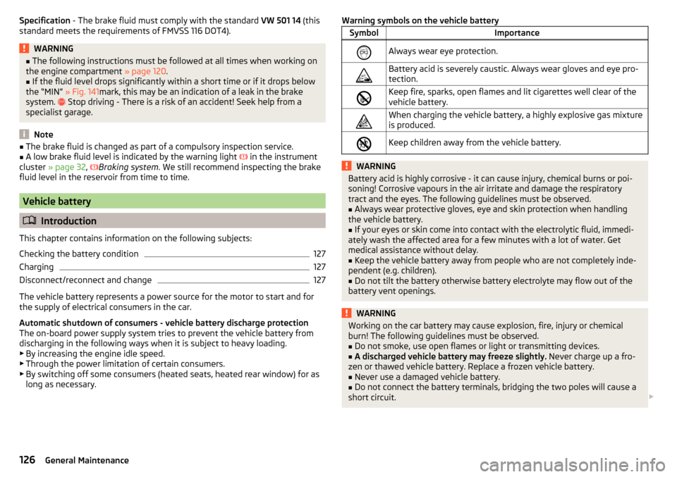
Fig. 141
Brake fluid reservoir
Check the brake fluid under the following conditions.
The vehicle is on a horizontal surface.
The engine is turned off.
Check brake fluid level - The brake fluid level must lie between the markings
“MIN” and “MAX” » Fig. 141.
125Inspecting and replenishing
Page 128 of 172
Specification - The brake fluid must comply with the standard VW 501 14 (this
standard meets the requirements of FMVSS 116 DOT4).WARNING■ The following instructions must be followed at all times when working on
the engine compartment » page 120.■
If the fluid level drops significantly within a short time or if it drops below
the “MIN” » Fig. 141mark, this may be an indication of a leak in the brake
system.
Stop driving - There is a risk of an accident! Seek help from a
specialist garage.
Note
■ The brake fluid is changed as part of a compulsory inspection service.■A low brake fluid level is indicated by the warning light in the instrument
cluster » page 32 ,
Braking system . We still recommend inspecting the brake
fluid level in the reservoir from time to time.
Vehicle battery
Introduction
This chapter contains information on the following subjects:
Checking the battery condition
127
Charging
127
Disconnect/reconnect and change
127
The vehicle battery represents a power source for the motor to start and for
the supply of electrical consumers in the car.
Automatic shutdown of consumers - vehicle battery discharge protection
The on-board power supply system tries to prevent the vehicle battery from
discharging in the following ways when it is subject to heavy loading. ▶ By increasing the engine idle speed.
▶ Through the power limitation of certain consumers.
▶ By switching off some consumers (heated seats, heated rear window) for as
long as necessary.
Warning symbols on the vehicle batterySymbolImportanceAlways wear eye protection.Battery acid is severely caustic. Always wear gloves and eye pro-
tection.Keep fire, sparks, open flames and lit cigarettes well clear of the
vehicle battery.When charging the vehicle battery, a highly explosive gas mixture
is produced.Keep children away from the vehicle battery.WARNINGBattery acid is highly corrosive - it can cause injury, chemical burns or poi-
soning! Corrosive vapours in the air irritate and damage the respiratory
tract and the eyes. The following guidelines must be observed.■
Always wear protective gloves, eye and skin protection when handling
the vehicle battery.
■
If your eyes or skin come into contact with the electrolytic fluid, immedi-
ately wash the affected area for a few minutes with a lot of water. Get
medical assistance without delay.
■
Keep the vehicle battery away from people who are not completely inde-
pendent (e.g. children).
■
Do not tilt the battery otherwise battery electrolyte may flow out of the
battery vent openings.
WARNINGWorking on the car battery may cause explosion, fire, injury or chemical
burn! The following guidelines must be observed.■
Do not smoke, use open flames or light or transmitting devices.
■
A discharged vehicle battery may freeze slightly. Never charge up a fro-
zen or thawed vehicle battery. Replace a frozen vehicle battery.
■
Never use a damaged vehicle battery.
■
Do not connect the battery terminals, bridging the two poles will cause a
short circuit.
126General Maintenance
Page 129 of 172
CAUTIONEnsure that battery acid does not come into contact with the bodywork – risk
of damage to the paintwork.
Note
■ We recommend having all work on the vehicle battery carried out by a spe-
cialist garage.■
You should replace batteries older than 5 years.
Checking the battery condition
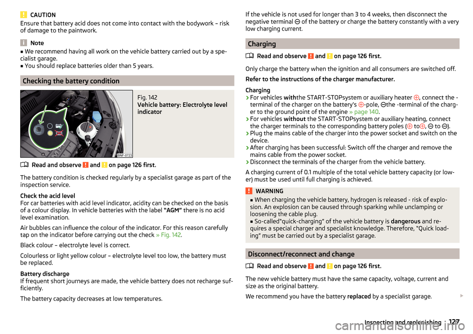
Fig. 142
Vehicle battery: Electrolyte level
indicator
Read and observe and on page 126 first.
The battery condition is checked regularly by a specialist garage as part of the inspection service.
Check the acid level
For car batteries with acid level indicator, acidity can be checked on the basis
of a colour display. In vehicle batteries with the label “AGM” there is no acid
level examination.
Air bubbles can influence the colour of the indicator. For this reason carefully
tap on the indicator before carrying out the check » Fig. 142.
Black colour – electrolyte level is correct.
Colourless or light yellow colour – electrolyte level too low, the battery must
be replaced.
Battery discharge
If frequent short journeys are made, the vehicle battery does not recharge suf-
ficiently.
The battery capacity decreases at low temperatures.
If the vehicle is not used for longer than 3 to 4 weeks, then disconnect the
negative terminal of the battery or charge the battery constantly with a very
low charging current.
Charging
Read and observe
and on page 126 first.
Only charge the battery when the ignition and all consumers are switched off.Refer to the instructions of the charger manufacturer.
Charging
›
For vehicles withthe START-STOPsystem or auxiliary heater
, connect the -
terminal of the charger on the battery’s -pole,
the -terminal of the charg-
er to the ground point of the engine » page 140.
›
For vehicles
without the START-STOPsystem or auxiliary heating, connect
the charger terminals to the corresponding battery poles ( to
,
to
).
›
Plug the mains cable of the charger into the power socket and switch on the
device.
›
After charging has been successful: Switch off the charger and remove the
mains cable from the power socket.
›
Disconnect the terminals of the charger from the vehicle battery.
A charging current of 0.1 multiple of the total vehicle battery capacity (or low-
er) must be used until full charging is achieved.
WARNING■ When charging the vehicle battery, hydrogen is released - risk of explo-
sion. An explosion can be caused through sparking while unclamping or
loosening the cable plug.■
So-called“quick-charging” of the vehicle battery is dangerous and re-
quires a special charger and specialist knowledge. Therefore, “Quick load-
ing” must be carried out by a specialist garage.
Disconnect/reconnect and change
Read and observe
and on page 126 first.
The new vehicle battery must have the same capacity, voltage, current and
size as the original battery.
We recommend you have the battery replaced by a specialist garage.
127Inspecting and replenishing
Page 136 of 172
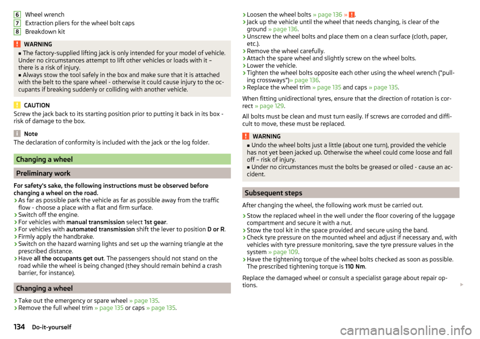
Wheel wrench
Extraction pliers for the wheel bolt caps
Breakdown kitWARNING■ The factory-supplied lifting jack is only intended for your model of vehicle.
Under no circumstances attempt to lift other vehicles or loads with it –
there is a risk of injury.■
Always stow the tool safely in the box and make sure that it is attached
with the belt to the spare wheel - otherwise it could cause injury to the oc-
cupants if breaking suddenly or colliding with another vehicle.
CAUTION
Screw the jack back to its starting position prior to putting it back in its box -
risk of damage to the box.
Note
The declaration of conformity is included with the jack or the log folder.
Changing a wheel
Preliminary work
For safety's sake, the following instructions must be observed before
changing a wheel on the road.
›
As far as possible park the vehicle as far as possible away from the traffic
flow - choose a place with a flat and firm surface.
›
Switch off the engine.
›
For vehicles with manual transmission select 1st gear .
›
For vehicles with
automated transmission shift the lever to position D or R.
›
Firmly apply the handbrake.
›
Switch on the hazard warning lights and set up the warning triangle at the
prescribed distance.
›
Have all the occupants get out . The passengers should not stand on the
road while the wheel is being changed (they should remain behind a crash
barrier, for instance).
Changing a wheel
›
Take out the emergency or spare wheel » page 135.
›
Remove the full wheel trim » page 135 or caps » page 135 .
678›Loosen the wheel bolts
» page 136 » .›Jack up the vehicle until the wheel that needs changing, is clear of the
ground » page 136 .›
Unscrew the wheel bolts and place them on a clean surface (cloth, paper,
etc.).
›
Remove the wheel carefully.
›
Attach the spare wheel and slightly screw on the wheel bolts.
›
Lower the vehicle.
›
Tighten the wheel bolts opposite each other using the wheel wrench (“pull- ing crossways”) » page 136.
›
Replace the wheel trim » page 135 and caps » page 135 .
When fitting unidirectional tyres, ensure that the direction of rotation is cor-
rect » page 129 .
All bolts must be clean and must turn easily. If screws are corroded and diffi-
cult to move, these must be replaced.
WARNING■ Undo the wheel bolts just a little (about one turn), provided the vehicle
has not yet been jacked up. Otherwise the wheel could come loose and fall
off – risk of injury.■
Under no circumstances must the bolts be greased or oiled - cause an ac-
cident.
Subsequent steps
After changing the wheel, the following work must be carried out.
›
Stow the replaced wheel in the well under the floor covering of the luggage
compartment and secure it with a nut.
›
Stow the tool kit in the space provided and secure using the band.
›
Check tyre pressure on the mounted wheel and adjust if necessary and, with
vehicles with tyre pressure monitoring, save the tyre pressure values in the
system » page 109 .
›
Have the tightening torque of the wheel bolts checked as soon as possible.
The prescribed tightening torque is 110 Nm.
Replace the damaged wheel or consult a specialist garage about repair op-
tions.
134Do-it-yourself
Page 146 of 172
›Remove the wiper blade in the direction of the arrow 3.
Attaching the windscreen wiper blade›
Slide the windscreen wiper blade in the opposite direction to arrow
3
until it
locks into place. Check that the windscreen wiper blade is correctly attached.
›
Fold the windscreen wiper arm back to the windscreen.
Fuses and light bulbs
Fuses
Introduction
Fig. 164
Blown fuse
This chapter contains information on the following subjects:
Fuses in the dash panel
145
Fuse arrangement in the dash panel
145
Fuses on the side of the dash panel
146
Assignment of the fuses on the side of the dash panel
146
Fuses in the engine compartment
147
Fuse arrangement in the engine compartment
147
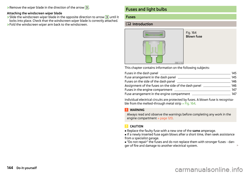
Individual electrical circuits are protected by fuses. A blown fuse is recognisa-
ble from the melted-through metal strip » Fig. 164.
WARNINGAlways read and observe the warnings before completing any work in the
engine compartment » page 120.
CAUTION
■
Replace the faulty fuse with a new one of the same amperage.■If a newly inserted fuse again blows after a short time, then seek assistance
from a specialist garage.■
“Do not repair” the fuses and do not replace them with stronger fuses - dan-
ger of fire and damage to another electrical system.
144Do-it-yourself
Page 150 of 172
We recommend having bulbs replaced by a specialist garage or seeking other
expert help in the event of any uncertainties.
▶ Switch off the ignition and all of the lights before replacing a bulb.
▶ Faulty bulbs must only be replaced with the same type of bulbs. The designa-
tion is located on the light socket or the glass bulb.
We recommend having the headlight settings checked by a specialist garage after replacing a bulb in the low or high beam unit or the fog lamp.
Visit a specialist garage if an LED diode is faulty.WARNING■ Always read and observe the warnings before completing any work in the
engine compartment » page 120.■
Accidents can be caused if the road in front of the vehicle is not suffi-
ciently illuminated and the vehicle cannot or can only be seen with difficul-
ty by other road users.
■
Bulbs H4, HB4 and H7 are pressurised and may burst when changed –
There is a risk of injury! We therefore recommended wearing gloves and
safety glasses when changing a bulb.
CAUTION
Do not take hold of the glass bulb with naked fingers (even the smallest
amount of dirt reduces the working life of the light bulb). Use a clean cloth,
napkin, or similar.
Note
■ This Owner's Manual only describes the replacement of bulbs where it is pos-
sible to replace the bulbs on your own without any complications arising. Other
bulbs must be replaced by a specialist garage.■
We recommend that a box of replacement bulbs always be carried in the ve-
hicle.
Bulb arrangement in the front headlightsFig. 171
Variant 1/Variant 2
Read and observe
and on page 148 first.
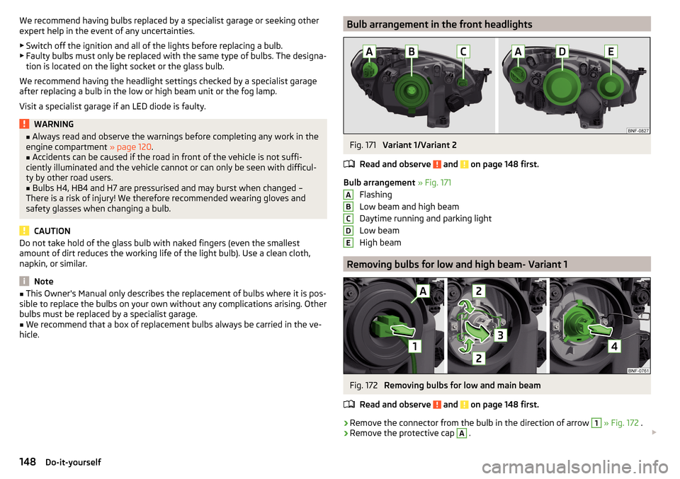
Bulb arrangement » Fig. 171
Flashing
Low beam and high beam
Daytime running and parking light
Low beam
High beam
Removing bulbs for low and high beam- Variant 1
Fig. 172
Removing bulbs for low and main beam
Read and observe
and on page 148 first.
›
Remove the connector from the bulb in the direction of arrow
1
» Fig. 172 .
›
Remove the protective cap
A
.
ABCDE148Do-it-yourself
Page 160 of 172
Broadcasting range82
buttons Swing Radio
76
Buttons Blues radio
76
C
Call list Call list
92
Car battery Disconnecting and reconnecting
127
Replacing127
Car care113
Exterior115
Interior116
Car computer see Multifunction display
39
Care and maintenance110
Carrier70
Car wash113
Car washing114
Exterior115
Interior116
washing114
CD86
Central locking42
problems45
Central locking button44
Change battery
142
Changing Windscreen wiper blades
143
Changing a wheel134
Changing134
Changing gear Selector lever
100
Tiptronic101
Changing wheels Wheels
134
Charging a vehicle battery127
Check Brake fluid
125
Engine oil124
Oil level124
Checking Battery condition
127
Coolant125
Checks Statutory checks
110
Children and safety21
Child safety lock45
Child seat21
Classification23
Installation location24, 25
in the passenger seat23
ISOFIX24, 25
on the front passenger seat22
on the passenger seat23
TOP TETHER26
Cigarette lighter62
City Safe Drive107
Disable/Enable108
Warning light36
Climatronic Automatic operation
73
Operating elements73
Clothes hook65
CNG120
Gas gauge31
Gas leaks120
In an accident120
Refuelling119
Regular checks120
Sticker120
cockpit29
Cockpit Lighting
52
Comfort signalling50
COMING HOME51
Compartments59
Compressed natural gas see CNG
120
Computer see Multifunction display
39
Conditions for pairing89
Coolant124
Checking125
Refilling125
Warning light33
Correct routing of seat belt
15
Correct seated position12
Correct seating position14
Cruise control system Warning light
36
Cruise Control System106
Cup holders61
D
DAB
82
DAY LIGHT see Daylight running lights
50
Daylight running lights50
Deactivation Airbag
20
Defrosting rear window53
Delayed locking of the boot lid See boot lid
46
Departure angle155
Digital Clock37
Digital Service Plan113
Dimmed headlights49
Dipstick124
Disclaimer75
Display Cardinal points
37
Fuel31
Fuel level31
158Index
Page 161 of 172
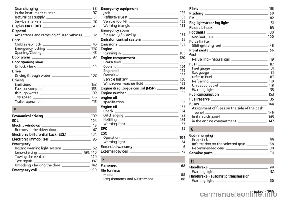
Gear changing38
In the instrument cluster37
Natural gas supply31
Service intervals42
Display MAXI DOT41
Disposal Acceptance and recycling of used vehicles
112
Door Child safety lock
45
Emergency locking142
Opening/Closing45
Door alarm37
Door opening lever Unlock / lock
44
Drive Driving through water
102
Driving Emissions
153
Fuel consumption153
through water102
Top speed156
Trailer operation112
E
Economical driving
102
EDL104
Electric windows46
Buttons in the driver door47
Electronic Differential Lock (EDL)104
Electronic immobiliser95
Emergency Hazard warning light system
52
Jump-starting139, 140
Towing the vehicle140
Tyre repair137
Unlocking / locking the door142
Emergency call90
Emergency equipment Jack133
Reflective vest133
Vehicle tool kit133
Warning triangle133
Emergency spare Removing / stowing
135
Emission control system35
Emissions153
Engine Running in
102
Engine compartment120
Brake fluid125
Coolant124
Engine oil123
Overview122
Vehicle battery126
Windscreen washer fluid123
Engine drag torque control (MSR)104
Engine number152
engine oil specification
123
Engine oil123
Check124
Oil changing123
Refilling124
Warning light33
EPC35
ESC Operation
104
Warning light34
Extended warranty6
External devices75
F
Fasteners
68
file formats media
88
Requirements and Restrictions88
Films115
Flashing50
FM82
Fog lights/rear fog light51
Foldable hook65
Footmats100
see footmats100
Force limiter Sliding/tilting roof
48
Front seats56
fuel Refuelling - natural gas
119
Fuel117
Fuel gauge31
Gas gauge31
refer to Fuel117
Refuelling118
Unleaded petrol118
Warning light35
Fuel consumption153
Fuel reserve35
Fuses144
Assignment of fuses on the side of the dash panel
146
in the dash panel145
in the engine compartment147
G
Gear changing Gear stick
99
Information on the selected gear38
Recommended gear38
Genuine parts111
H
Handbrake
98
Warning light32
Handbrake - automatic transmission Warning light
36
159Index