stop start SKODA CITIGO 2016 1.G User Guide
[x] Cancel search | Manufacturer: SKODA, Model Year: 2016, Model line: CITIGO, Model: SKODA CITIGO 2016 1.GPages: 172, PDF Size: 24.59 MB
Page 99 of 172
OperationFig. 118
Display
Vehicles with manual transmission
The engine is automatically switched offas soon as the vehicle comes to a halt,
the shift lever is moved into neutral and the clutch pedal is released.
The engine is automatically startedas soon as the clutch pedal is depressed.
Vehicles with automatic transmission
The engine is automatically switched offas soon as the vehicle comes to a
standstill and the brake pedal is operated.
The engine is automatically startedas soon as the brake pedal is released.
Requirements for the system to function correctly
The following conditions must be met for the system to function correctly.
The driver's door is closed.
The driver has fastened the seat belt.
The bonnet is closed.
The driving speed was higher than 4 km/h after the last stop.
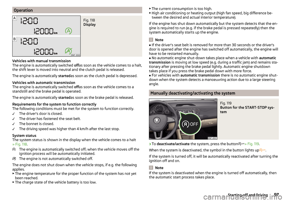
System status
The system status is shown in the display when the vehicle comes to a halt
» Fig. 118 .
The engine is automatically switched off; when the vehicle moves off the
ignition process will be automatically initiated.
The engine is not automatically switched off.
The engine does not shut down when the vehicle stops, if e.g. the following
applies.
▶ The engine temperature for the proper function of the system has not yet
been reached.
▶ The charge state of the vehicle battery is too low.
▶
The current consumption is too high.
▶ High air conditioning or heating output (high fan speed, big difference be-
tween the desired and actual interior temperature).
If the engine has shut down automatically but the system detects that the en-
gine is required to run (e.g. if the brake pedal is pressed repeatedly) then the
system automatically starts up the engine.
Note
■ If the driver's seat belt is removed for more than 30 seconds or the driver's
door is opened after the engine has switched off automatically, the engine will
have to be restarted manually.■
No automatic engine shut-down takes place when a vehicle with automatic
transmission is moving at low speed (e.g. during a traffic jam) and remains sta-
tionary after pressing the brake pedal lightly. Automatic engine shutdown
takes place if you press the brake pedal down with more force.
■
For vehicles with automatic transmission there is no automatic engine shut-
down when the system detects a manoeuvring action due to a large steering
angle.
Manually deactivating/activating the system
Fig. 119
Button for the START-STOP sys-
tem
›
To deactivate/activate the system, press the button
» Fig. 119 .
When the system is deactivated, the symbol in the button lights up
.
If the system is turned off, it will be automatically reactivated after turning the
ignition off and on.
Note
If the system is deactivated when the engine is turned off automatically, then
the automatic start process takes place.97Starting-off and Driving
Page 101 of 172
›Move the lever right down while pressing the lock button.
The handbrake warning light
lights up when the handbrake is applied, pro-
vided the ignition is on.
A warning signal sounds if the vehicle is inadvertently driven off with the
handbrake applied. The handbrake warning is activated if the vehicle is driven
at a speed of over 5 km/h for more than 3 seconds.WARNINGDisengage the handbrake completely. A handbrake which is only partially
disengaged can result in the rear brakes overheating. This can have a nega-
tive effect on the operation of the brake system – risk of accident!
Parking
Read and observe
on page 98 first.
When stopping and parking, look for a place with a suitable surface » .
Only carry out the activities while parking in the specified order.
›
Bring the vehicle to a stop and depress the brake pedal.
›
Firmly apply the handbrake.
›
For vehicles with automated gearbox shift the lever to position D or R.
›
Switch off the engine.
›
For vehicles with manual transmission , select 1st gear or Reverse gear R .
›
Release the brake pedal.
WARNING■
The parts of the exhaust system can become very hot. Therefore, never
stop the vehicle in places where the underside of your vehicle could come
into contact with flammable materials (e.g. dry grass, leaves, spilled fuel or
the like). - Risk of fire and serious injury can occur!■
When leaving the vehicle never leave people unattended in the car who
could, for example, lock the vehicle or release the brake - risk of accidents
and injury!
Manual gear changing and pedals
Introduction
This chapter contains information on the following subjects:
Manual gear changing
99
Pedals
100
Manual gear changing
Fig. 121
The shift pattern
The shift pattern for the individual gear positions is shown on the gear lever » Fig. 121 .
The gearshift indicator should be observed when changing gear » page 38.
Always depress the clutch pedal all the way down. This prevents uneven wear
to the clutch.
Reverse gear is engaged
›
Stop the vehicle.
›
The clutch pedal is fully depressed.
›
Move the shift lever to the NPosition and wait for a short time.
›
Push down on the shift lever, then push fully over to the right and then back-
wards, to position R» Fig. 121 .
The reversing lights will come on once reverse gear is engaged, provided the
ignition is on.
WARNINGNever engage reverse gear when driving – risk of accident! 99Starting-off and Driving
Page 102 of 172
CAUTIONIf not in the process of changing gear, do not leave your hand on the gearshift
lever while driving. The pressure from the hand can cause the gearshift mech-
anism to wear excessively.
Pedals
The operation of the pedals must not be hindered under any circumstances!
Only a floor mat (ex-factory or from the ŠKODA Original Accessories range)
which can be secured to the attachment points should be used in the driver's
footwell.
WARNINGThere should be no objects in the driver's footwell, otherwise the pedal op-
eration can be impeded - risk of accident!
Automated transmission
Introduction
This chapter contains information on the following subjects:
Select lever position
100
Manual shifting (Tiptronic)
101
Starting-off and driving
101
The automatic transmission changes gears automatically based on how the
engine and accelerator are being worked, the vehicle speed and the selected
driving mode.
The automatic transmission modes are set by the driver by means of the selec-
tor lever.
WARNING■ Do not accelerate when selecting drive mode prior to moving off - risk of
accident!■
Never move the selector lever to mode R when driving – risk of accident!
■
Always firmly apply the handbrake before leaving the vehicle! Otherwise,
the vehicle could be automatically set in motion - there is a risk of acci-
dents!
CAUTIONWhen stopping on a slope, never try to hold the vehicle using the accelerator
pedal – this may lead to gear damage.
Note
■ The engine can only be left on in position N, when the brake pedal is de-
pressed .■
If the selector lever position N is accidentally selected while driving, it is first
necessary to release pressure on the accelerator pedal and wait for the idling
speed of the engine to be reached before the selector lever can be engaged in
the drive position.
■
If the N symbol flashes next to the selector lever, engage the selector lever
position N.
Select lever position
Fig. 122
Selector lever positions
Read and observe and on page 100 first.
The selector lever can be moved through shifting to one of the following posi-
tions » Fig. 122 .
Neutral (idle position) - Power transmission to the drive wheels is inter-
rupted.
Reverse gear - The position can only be selected when the vehicle is sta-
tionary and the engine is idling.
The brake pedal must be depressed before setting into position R from
position N.
Forward drive mode
The brake pedal must be depressed before setting into position D from
position N.
Manual shifting (Tiptronic) - further information » page 101
NRDM100Driving
Page 103 of 172
With driving mode set, the vehicle will not start up
If the vehicle does not start off, the problem may be that the selector lever is
not completely in the selected position. In such an instance, press the brake
pedal and put the selector lever into the required position.
Manual shifting (Tiptronic)
Fig. 123
Selector lever / display
Read and observe
and on page 100 first.
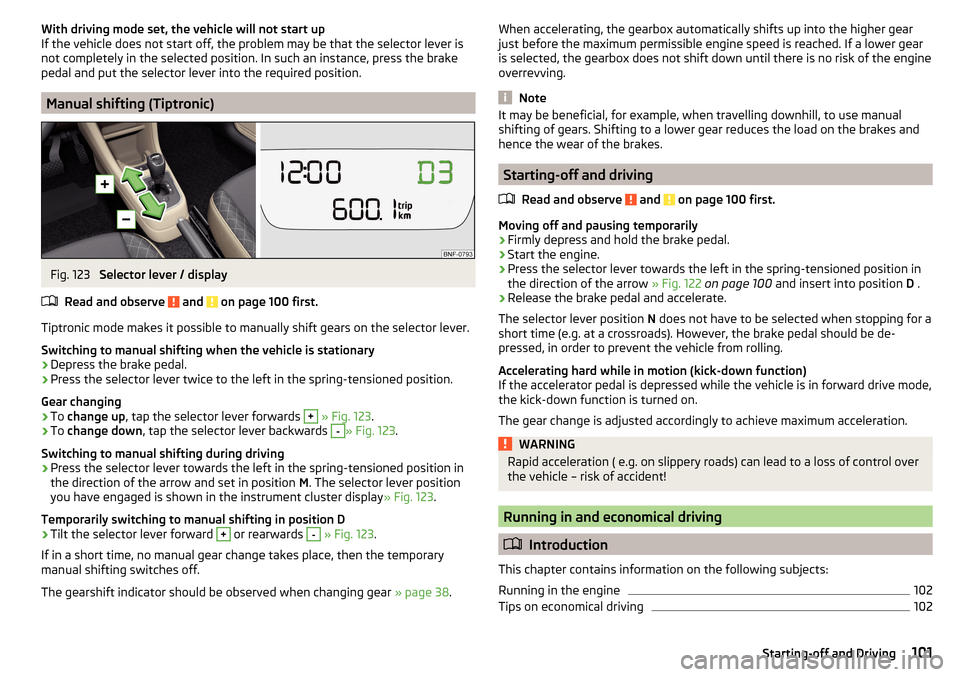
Tiptronic mode makes it possible to manually shift gears on the selector lever. Switching to manual shifting when the vehicle is stationary
›
Depress the brake pedal.
›
Press the selector lever twice to the left in the spring-tensioned position.
Gear changing
›
To change up , tap the selector lever forwards
+
» Fig. 123 .
›
To change down , tap the selector lever backwards
-
» Fig. 123.
Switching to manual shifting during driving
›
Press the selector lever towards the left in the spring-tensioned position in
the direction of the arrow and set in position M. The selector lever position
you have engaged is shown in the instrument cluster display » Fig. 123.
Temporarily switching to manual shifting in position D
›
Tilt the selector lever forward
+
or rearwards
-
» Fig. 123 .
If in a short time, no manual gear change takes place, then the temporary
manual shifting switches off.
The gearshift indicator should be observed when changing gear » page 38.
When accelerating, the gearbox automatically shifts up into the higher gear
just before the maximum permissible engine speed is reached. If a lower gear
is selected, the gearbox does not shift down until there is no risk of the engine
overrevving.
Note
It may be beneficial, for example, when travelling downhill, to use manual
shifting of gears. Shifting to a lower gear reduces the load on the brakes and
hence the wear of the brakes.
Starting-off and driving
Read and observe
and on page 100 first.
Moving off and pausing temporarily
›
Firmly depress and hold the brake pedal.
›
Start the engine.
›
Press the selector lever towards the left in the spring-tensioned position in
the direction of the arrow » Fig. 122 on page 100 and insert into position D .
›
Release the brake pedal and accelerate.
The selector lever position N does not have to be selected when stopping for a
short time (e.g. at a crossroads). However, the brake pedal should be de-
pressed, in order to prevent the vehicle from rolling.
Accelerating hard while in motion (kick-down function)
If the accelerator pedal is depressed while the vehicle is in forward drive mode,
the kick-down function is turned on.
The gear change is adjusted accordingly to achieve maximum acceleration.
WARNINGRapid acceleration ( e.g. on slippery roads) can lead to a loss of control over
the vehicle – risk of accident!
Running in and economical driving
Introduction
This chapter contains information on the following subjects:
Running in the engine
102
Tips on economical driving
102101Starting-off and Driving
Page 108 of 172
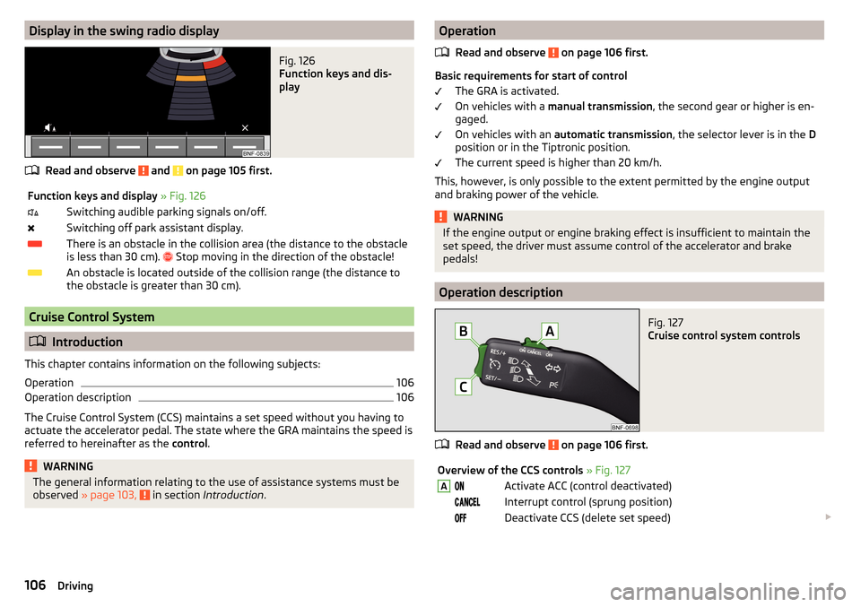
Display in the swing radio displayFig. 126
Function keys and dis-
play
Read and observe and on page 105 first.
Function keys and display » Fig. 126Switching audible parking signals on/off.Switching off park assistant display.There is an obstacle in the collision area (the distance to the obstacle
is less than 30 cm).
Stop moving in the direction of the obstacle!An obstacle is located outside of the collision range (the distance to
the obstacle is greater than 30 cm).
Cruise Control System
Introduction
This chapter contains information on the following subjects:
Operation
106
Operation description
106
The Cruise Control System (CCS) maintains a set speed without you having to
actuate the accelerator pedal. The state where the GRA maintains the speed is
referred to hereinafter as the control.
WARNINGThe general information relating to the use of assistance systems must be
observed » page 103, in section Introduction .Operation
Read and observe
on page 106 first.
Basic requirements for start of control The GRA is activated.
On vehicles with a manual transmission , the second gear or higher is en-
gaged.
On vehicles with an automatic transmission , the selector lever is in the D
position or in the Tiptronic position.
The current speed is higher than 20 km/h.
This, however, is only possible to the extent permitted by the engine output
and braking power of the vehicle.
WARNINGIf the engine output or engine braking effect is insufficient to maintain the
set speed, the driver must assume control of the accelerator and brake
pedals!
Operation description
Fig. 127
Cruise control system controls
Read and observe on page 106 first.
Overview of the CCS controls » Fig. 127AActivate ACC (control deactivated) Interrupt control (sprung position) Deactivate CCS (delete set speed) 106Driving
Page 128 of 172
Specification - The brake fluid must comply with the standard VW 501 14 (this
standard meets the requirements of FMVSS 116 DOT4).WARNING■ The following instructions must be followed at all times when working on
the engine compartment » page 120.■
If the fluid level drops significantly within a short time or if it drops below
the “MIN” » Fig. 141mark, this may be an indication of a leak in the brake
system.
Stop driving - There is a risk of an accident! Seek help from a
specialist garage.
Note
■ The brake fluid is changed as part of a compulsory inspection service.■A low brake fluid level is indicated by the warning light in the instrument
cluster » page 32 ,
Braking system . We still recommend inspecting the brake
fluid level in the reservoir from time to time.
Vehicle battery
Introduction
This chapter contains information on the following subjects:
Checking the battery condition
127
Charging
127
Disconnect/reconnect and change
127
The vehicle battery represents a power source for the motor to start and for
the supply of electrical consumers in the car.
Automatic shutdown of consumers - vehicle battery discharge protection
The on-board power supply system tries to prevent the vehicle battery from
discharging in the following ways when it is subject to heavy loading. ▶ By increasing the engine idle speed.
▶ Through the power limitation of certain consumers.
▶ By switching off some consumers (heated seats, heated rear window) for as
long as necessary.
Warning symbols on the vehicle batterySymbolImportanceAlways wear eye protection.Battery acid is severely caustic. Always wear gloves and eye pro-
tection.Keep fire, sparks, open flames and lit cigarettes well clear of the
vehicle battery.When charging the vehicle battery, a highly explosive gas mixture
is produced.Keep children away from the vehicle battery.WARNINGBattery acid is highly corrosive - it can cause injury, chemical burns or poi-
soning! Corrosive vapours in the air irritate and damage the respiratory
tract and the eyes. The following guidelines must be observed.■
Always wear protective gloves, eye and skin protection when handling
the vehicle battery.
■
If your eyes or skin come into contact with the electrolytic fluid, immedi-
ately wash the affected area for a few minutes with a lot of water. Get
medical assistance without delay.
■
Keep the vehicle battery away from people who are not completely inde-
pendent (e.g. children).
■
Do not tilt the battery otherwise battery electrolyte may flow out of the
battery vent openings.
WARNINGWorking on the car battery may cause explosion, fire, injury or chemical
burn! The following guidelines must be observed.■
Do not smoke, use open flames or light or transmitting devices.
■
A discharged vehicle battery may freeze slightly. Never charge up a fro-
zen or thawed vehicle battery. Replace a frozen vehicle battery.
■
Never use a damaged vehicle battery.
■
Do not connect the battery terminals, bridging the two poles will cause a
short circuit.
126General Maintenance
Page 129 of 172
CAUTIONEnsure that battery acid does not come into contact with the bodywork – risk
of damage to the paintwork.
Note
■ We recommend having all work on the vehicle battery carried out by a spe-
cialist garage.■
You should replace batteries older than 5 years.
Checking the battery condition
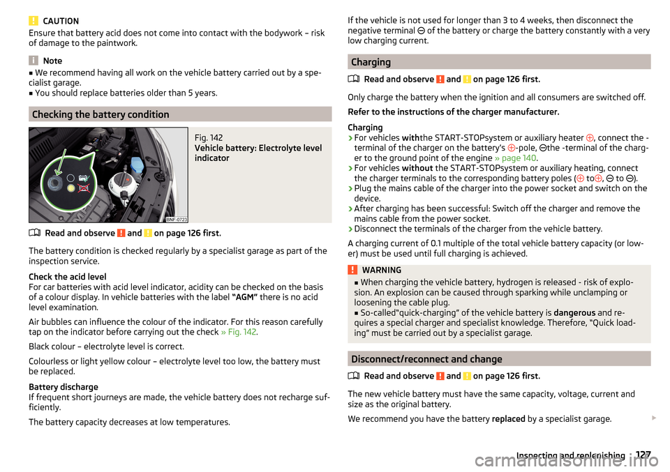
Fig. 142
Vehicle battery: Electrolyte level
indicator
Read and observe and on page 126 first.
The battery condition is checked regularly by a specialist garage as part of the inspection service.
Check the acid level
For car batteries with acid level indicator, acidity can be checked on the basis
of a colour display. In vehicle batteries with the label “AGM” there is no acid
level examination.
Air bubbles can influence the colour of the indicator. For this reason carefully
tap on the indicator before carrying out the check » Fig. 142.
Black colour – electrolyte level is correct.
Colourless or light yellow colour – electrolyte level too low, the battery must
be replaced.
Battery discharge
If frequent short journeys are made, the vehicle battery does not recharge suf-
ficiently.
The battery capacity decreases at low temperatures.
If the vehicle is not used for longer than 3 to 4 weeks, then disconnect the
negative terminal of the battery or charge the battery constantly with a very
low charging current.
Charging
Read and observe
and on page 126 first.
Only charge the battery when the ignition and all consumers are switched off.Refer to the instructions of the charger manufacturer.
Charging
›
For vehicles withthe START-STOPsystem or auxiliary heater
, connect the -
terminal of the charger on the battery’s -pole,
the -terminal of the charg-
er to the ground point of the engine » page 140.
›
For vehicles
without the START-STOPsystem or auxiliary heating, connect
the charger terminals to the corresponding battery poles ( to
,
to
).
›
Plug the mains cable of the charger into the power socket and switch on the
device.
›
After charging has been successful: Switch off the charger and remove the
mains cable from the power socket.
›
Disconnect the terminals of the charger from the vehicle battery.
A charging current of 0.1 multiple of the total vehicle battery capacity (or low-
er) must be used until full charging is achieved.
WARNING■ When charging the vehicle battery, hydrogen is released - risk of explo-
sion. An explosion can be caused through sparking while unclamping or
loosening the cable plug.■
So-called“quick-charging” of the vehicle battery is dangerous and re-
quires a special charger and specialist knowledge. Therefore, “Quick load-
ing” must be carried out by a specialist garage.
Disconnect/reconnect and change
Read and observe
and on page 126 first.
The new vehicle battery must have the same capacity, voltage, current and
size as the original battery.
We recommend you have the battery replaced by a specialist garage.
127Inspecting and replenishing
Page 141 of 172
›For vehicles with
automated manual transmission leave the selector lever in
position N.›
Check that the screw for the tire pressure reduction
6
is closed.
›
Start the engine.
›
Plug the connector
4
into 12 volt socket » page 63, 12-volt socket .
›
Switch on the air compressor with the ON and OFF switch
9
.
›
Once tyre inflation pressure of 2.0-2.5 bar has been reached, turn off the air
compressor. Maximum run time of 6 minutes » .
›
If you cannot reach an air pressure of 2.0 - 2.5 bar, unscrew the tyre inflation
hose
8
from the tyre valve.
›
Drive the vehicle 10 metres forwards or backwards to allow the sealing agent
to “distribute” in the tyre.
›
Firmly screw the tyre inflation hose
8
back onto the tyre valve and repeat
the inflation process.
›
Stick the sticker
1
» Fig. 154 on page 138 on the dash panel in the driver's
field of view.
At a tyre inflation pressure of 2.0 – 2.5 bar, the journey can be continued at a maximum speed of 80 km/h or 50 mph.
WARNING■ If the tire does not inflate at least. 2.0 bar, the damage is too great. The
sealing agent cannot be used to seal the tyre. Stop driving! Seek help
from a specialist garage.■
The tyre inflation hose and air compressor may get hot as the tyre is be-
ing inflated – risk of burning.
CAUTION
Switch off the air compressor if it has been running for as much as 6 minutes –
risk of damage to the compressor! Allow the air compressor to cool a few mi-
nutes before switching it on again.
Information on driving with repaired tyres
Read and observe
on page 137 first.
The inflation pressure of the repaired tyre must be checked after driving for 10minutes.
If the tyre pressure is 1.3 bar or less
›
The tyre cannot be properly sealed with the breakdown kit.
Do not contin-
ue to drive! Seek help from a specialist garage.
If the tyre pressure is 1.3 bar or more›Set the tyre pressure back to the correct value » page 129.›
Continue driving carefully to the nearest specialist garage at a maximum
speed of 80 km/h (50 mph).
WARNINGA tyre filled with sealant has the same driving characteristics as a standard
tyre. The following guidelines must therefore be observed.■
Do not drive faster than 80 km/h (50 mph).
■
Avoid accelerating at full throttle, sharp braking and fast cornering.
Jump-starting
Introduction
This chapter contains information on the following subjects:
Jump-starting using the battery from another vehicle
140WARNING■ The following instructions must be followed at all times when working on
the engine compartment » page 120.■
When handling the vehicle battery, the following warnings must be ob-
served » page 126 .
■
A discharged vehicle battery may already freeze at temperatures just be-
low 0 °C. If the battery is frozen, do not carry out a jump start with the bat-
tery of another vehicle – risk of explosion and injury!
■
Never jump-start vehicle batteries with an electrolyte level that is too low
– risk of explosion and caustic burns.
139Emergency equipment and self-help
Page 142 of 172
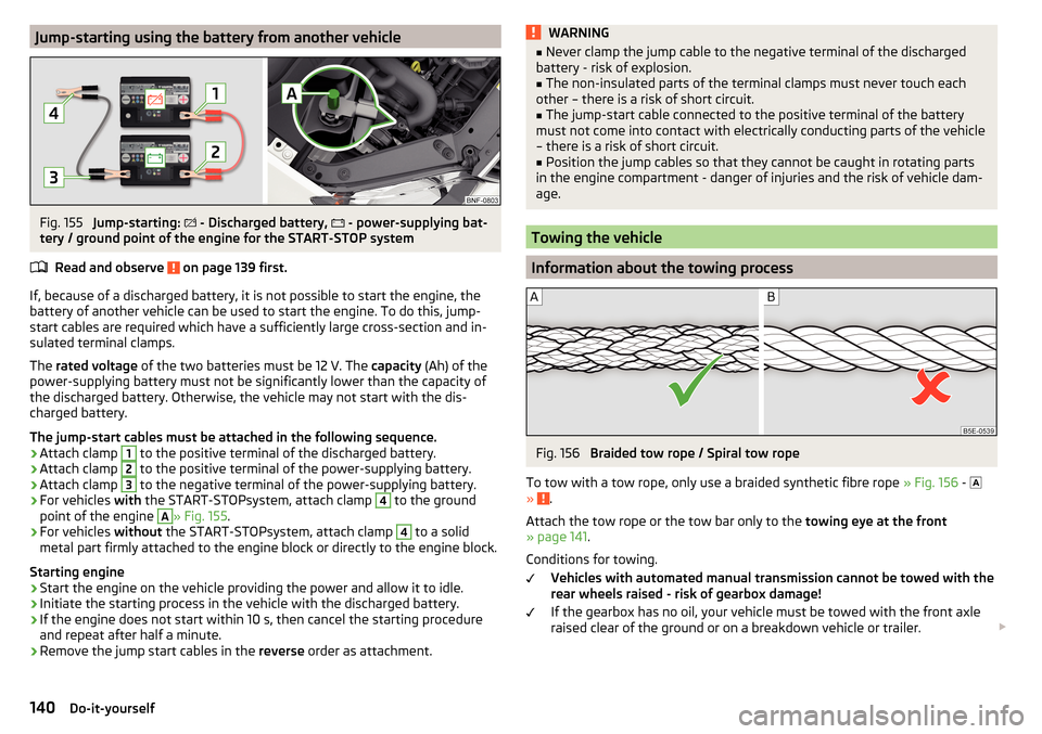
Jump-starting using the battery from another vehicleFig. 155
Jump-starting:
- Discharged battery,
- power-supplying bat-
tery / ground point of the engine for the START-STOP system
Read and observe
on page 139 first.
If, because of a discharged battery, it is not possible to start the engine, the
battery of another vehicle can be used to start the engine. To do this, jump-
start cables are required which have a sufficiently large cross-section and in-
sulated terminal clamps.
The rated voltage of the two batteries must be 12 V. The capacity (Ah) of the
power-supplying battery must not be significantly lower than the capacity of
the discharged battery. Otherwise, the vehicle may not start with the dis-
charged battery.
The jump-start cables must be attached in the following sequence.
›
Attach clamp
1
to the positive terminal of the discharged battery.
›
Attach clamp
2
to the positive terminal of the power-supplying battery.
›
Attach clamp
3
to the negative terminal of the power-supplying battery.
›
For vehicles with the START-STOPsystem, attach clamp
4
to the ground
point of the engine
A
» Fig. 155 .
›
For vehicles without the START-STOPsystem, attach clamp
4
to a solid
metal part firmly attached to the engine block or directly to the engine block.
Starting engine
›
Start the engine on the vehicle providing the power and allow it to idle.
›
Initiate the starting process in the vehicle with the discharged battery.
›
If the engine does not start within 10 s, then cancel the starting procedure
and repeat after half a minute.
›
Remove the jump start cables in the reverse order as attachment.
WARNING■
Never clamp the jump cable to the negative terminal of the discharged
battery - risk of explosion.■
The non-insulated parts of the terminal clamps must never touch each
other – there is a risk of short circuit.
■
The jump-start cable connected to the positive terminal of the battery
must not come into contact with electrically conducting parts of the vehicle
– there is a risk of short circuit.
■
Position the jump cables so that they cannot be caught in rotating parts
in the engine compartment - danger of injuries and the risk of vehicle dam-
age.
Towing the vehicle
Information about the towing process
Fig. 156
Braided tow rope / Spiral tow rope
To tow with a tow rope, only use a braided synthetic fibre rope » Fig. 156 -
»
.
Attach the tow rope or the tow bar only to the towing eye at the front
» page 141 .
Conditions for towing. Vehicles with automated manual transmission cannot be towed with the
rear wheels raised - risk of gearbox damage!
If the gearbox has no oil, your vehicle must be towed with the front axle
raised clear of the ground or on a breakdown vehicle or trailer.
140Do-it-yourself
Page 147 of 172
Note■We recommend always carrying replacement fuses in the vehicle.■There can be several power consuming devices for one fuse. Multiple fuses
may exist for a single power consuming device.
Fuses in the dash panel
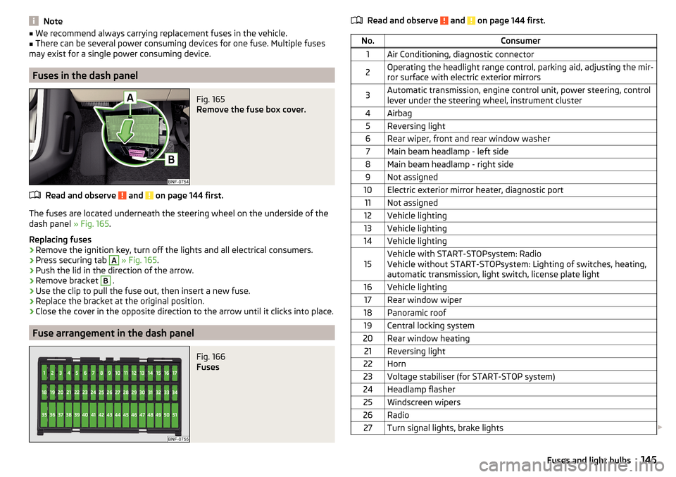
Fig. 165
Remove the fuse box cover.
Read and observe and on page 144 first.
The fuses are located underneath the steering wheel on the underside of the
dash panel » Fig. 165.
Replacing fuses
›
Remove the ignition key, turn off the lights and all electrical consumers.
›
Press securing tab
A
» Fig. 165 .
›
Push the lid in the direction of the arrow.
›
Remove bracket
B
.
›
Use the clip to pull the fuse out, then insert a new fuse.
›
Replace the bracket at the original position.
›
Close the cover in the opposite direction to the arrow until it clicks into place.
Fuse arrangement in the dash panel
Fig. 166
Fuses
Read and observe and on page 144 first.No.Consumer1Air Conditioning, diagnostic connector2Operating the headlight range control, parking aid, adjusting the mir-
ror surface with electric exterior mirrors3Automatic transmission, engine control unit, power steering, control
lever under the steering wheel, instrument cluster4Airbag5Reversing light6Rear wiper, front and rear window washer7Main beam headlamp - left side8Main beam headlamp - right side9Not assigned10Electric exterior mirror heater, diagnostic port11Not assigned12Vehicle lighting13Vehicle lighting14Vehicle lighting15Vehicle with START-STOPsystem: Radio
Vehicle without START-STOPsystem: Lighting of switches, heating,
automatic transmission, light switch, license plate light16Vehicle lighting17Rear window wiper18Panoramic roof19Central locking system20Rear window heating21Reversing light22Horn23Voltage stabiliser (for START-STOP system)24Headlamp flasher25Windscreen wipers26Radio27Turn signal lights, brake lights 145Fuses and light bulbs