jump start SKODA CITIGO 2017 Owners Manual
[x] Cancel search | Manufacturer: SKODA, Model Year: 2017, Model line: CITIGO, Model: SKODA CITIGO 2017Pages: 172, PDF Size: 24.54 MB
Page 6 of 172
Inspecting and replenishing117Fuel117
Engine compartment
120
Engine oil
123
Coolant
124
Brake fluid
125
Vehicle battery
126
Wheels
128
Wheels and tyres
128
Operating in winter conditions
131
Do-it-yourself
Emergency equipment and self-help
133
Emergency equipment
133
Changing a wheel
134
Breakdown kit
137
Jump-starting
139
Towing the vehicle
140
Remote
142
Emergency unlocking / unlocking of doors
142
Replacing windscreen wiper blades
143
Fuses and light bulbs
144
Fuses
144
Bulbs
147
Technical data
Technical data
152
Basic vehicle data
152
Vehicle-specific data depending on the
engine
156
Index
4Table of Contents
Page 88 of 172
If no audio source is chosen within 5 seconds, then the main menu of the last
selected audio source is displayed.›
To select the audio source in the folder / track list the function button
repeatedly until the display on the position
B
» Fig. 101 on page 84
is dis-
played.
›
Press the function key
. Using the dial
Select the sound source » Fig. 103
and select the desired folder / track.
Playback starts automatically (does not apply to AUX).
If AUX is selected as the audio source, the playback must be started on the
connected device.
CAUTION
■ Do not save any important data or that which has not been backed up on the
connected audio sources. ŠKODA assumes no responsibility for lost or dam-
aged files or connected audio sources.■
When changing or connecting an audio source, this may cause sudden
changes in volume. Reduce the volume before changing or connecting an au-
dio source.
■
When connecting an external audio source, the external source information
messages can be displayed. These messages must be observed and if neces-
sary confirmed (e.g. enabling data transfer etc).
Note
The national copyright laws that apply in your country must be observed.
SD-card
Fig. 104
Insert the SD card
›
Insert the SD card in the slot in the direction of the arrow (with the cut end
facing upwards), until it“locks” » Fig. 104.
›
Applies to Swing: To remove press the button
→
→
Remove source safely
→
SD card
.
› Applies to
Blues: Toremove , press the key
→ Remove source safely → SDcard
.›
Press on the inserted SD memory card. The SD card “jumps” into the eject
position.
CAUTION
■ Do not use an SD card with a broken write protection slide - there is a risk of
damage to the SD card reader!■
When using an SD card with an adapter, vehicle vibrations might cause the
card to fall out of the adapter.
CD
Applies to Blues.
›
To insert a CD, with the labelled side facing up, into the CD slot until it is au-
tomatically drawn in.
›
To eject , press the button , the CD is manoeuvred to the eject position.
If the ejected CD is not removed within 10 seconds, it is retracted again for
safety reasons.
WARNING■ The CD-player is a laser product.■This laser product classified in accordance with national / international
standards DIN EN 60825-1: 2008-05 and DHHS Rules 21 CFR. Subchapter J
classified as a Class 1 laser product to the date of manufacture. The laser
used in this class 1 laser product is so weak that there is no risk of danger
when operated correctly.■
This product is designed such that the laser is restricted to the inside of
the unit. However, the installed laser could be classified in a higher class
were the housing to be removed. For this reason, never remove the unit
housing.
CAUTION
■ Be sure to remove the CD before you try to insert a new CD. Otherwise you
can damage the drive inside the unit.■
Insert into the CD drive only original audio CDs or standardised CD-R/RWs.
■
Do not stick anything to the CDs!
86Infotainment
Page 89 of 172
■If the ambient temperature is too high or too low, the CD playback may not
function properly.■
Damp (condensation) may affect the device in cold weather or high humidity.
This can cause the CD to jump or impair the play function. Once the moisture
has dissipated, playback is fully functional again.
Note
■ After pressing the button , there is a delay of a few seconds before the CD
is ejected.■
On uneven or unpaved roads, playback jumps may occur.
■
If the CD is damaged, is not readable or is inserted incorrectly, the following
message is displayed
CD is unreadable
.
■
It is possible that CDs protected by copyright cannot not be played back at all
or only in certain circumstances.
USB input
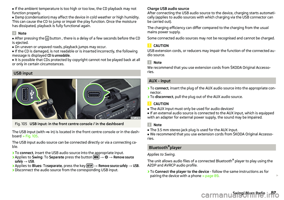
Fig. 105
USB input: in the front centre console / in the dashboard
The USB input (with in) is located in the front centre console or in the dash-
board » Fig. 105 .
The USB input audio source can be connected directly or via a connecting ca-
ble.
›
To connect , insert the USB audio source into the appropriate input.
›
Applies to Swing: To Separate press the button
→
→
Remove sourcesafely
→
USB
.
›
Applies to Blues: Toseparate , press the key
→
Remove source safely
→
USB
.
›
Disconnect the audio source from the corresponding USB input.
Charge USB audio source
After connecting the USB audio source to the device, charging starts automati-
cally (applies to audio sources with which charging via the USB connector can
be carried out).
The charging efficiency can differ compared to the charging from the usual
mains power supply.
Some connected audio sources may not be recognised and cannot be charged.
CAUTION
USB extension cords, or reducers may impair the function of the connected au-
dio source.
Note
We recommend that you use extension cords from ŠKODA Original Accesso-
ries.
AUX - input
›
To connect , insert the plug of the AUX audio source into the appropriate con-
nector.
›
To disconnect , pull the plug out of the AUX audio source.
CAUTION
■
The AUX input must only be used for audio devices!■If an external audio source is connected to the AUX input, which is equipped
with an adapter for external power supply, the sound may be impaired.
Note
■ The 3.5 mm stereo jack plug is used for the AUX input.■We recommend that you use extension cords from ŠKODA Original Accesso-
ries.
Bluetooth ®
player
Applies to Swing.
The unit allows audio files of a connected Bluetooth ®
player to play using the
A2DP and AVRCP audio profile.
›
To Connect the player to the device - follow the same instructions as for
pairing the device with a phone » page 89.
87Swing/ Blues Radio
Page 97 of 172
Driving
Starting-off and Driving
Starting and stopping the engine
Introduction
This chapter contains information on the following subjects:
Electronic immobiliser and steering lock
95
Ignition on / off
96
Starting / Stopping the engine
96
It is possible, with the key in the ignition, to switch the ignition off and on and
start/stop the engine.
WARNING■ Never switch off the engine before the vehicle is stationary – risk of acci-
dent!■
While driving with the engine stopped the ignition must always be
switched on. Otherwise, the steering may lock - danger of an accident!
■
Do not withdraw the ignition key from the ignition lock until the vehicle
has come to a stop » page 99, Parking . Otherwise, the steering may lock -
danger of an accident!
■
Never leave the vehicle unattended with the engine running - risk of acci-
dent, theft or similar.
■
Never (e.g. in garages) run the engine in a closed place - there is the dan-
ger of poisoning and death!
CAUTION
■ Only start the engine when the engine and the vehicle are stationary - there
is a danger of starter and engine damage!■
Do not push-start the engine – risk of damaging the engine and the catalytic
converter. The battery from another vehicle can be used as a jump-start aid.
Note
Do not warm up the engine while the vehicle is stationary. If possible, start
your journey as soon as the engine has started. Through this, the engine rea-
ches its operating temperature faster.Electronic immobiliser and steering lock
Read and observe
and on page 95 first.
The electronic immobiliser (hereinafter referred to as immobiliser) makes thetheft or unauthorised use of your vehicle more difficult.
Immobiliser
The immobiliser allows the engine to start provided an original vehicle key only
is used.
Malfunction of the immobiliser
It is not possible to start the engine if there is a failure of the components in
the immobiliser key.
Use the other vehicle key to start the engine; if necessary, seek help from a
specialist garage.
Steering lock - lock
›
Remove the key and turn the steering wheel until the steering lock engages.
Steering lock - unlock
›
Insert the key into the ignition and turn on the ignition. If this is not possible,
then move the steering wheel slightly back and forth, as a result of which
the steering lock should unlock.
WARNINGNever let the vehicle roll with locked steering lock - danger of accident!95Starting-off and Driving
Page 141 of 172
›For vehicles with
automated manual transmission leave the selector lever in
position N.›
Check that the screw for the tire pressure reduction
6
is closed.
›
Start the engine.
›
Plug the connector
4
into 12 volt socket » page 63, 12-volt socket .
›
Switch on the air compressor with the ON and OFF switch
9
.
›
Once tyre inflation pressure of 2.0-2.5 bar has been reached, turn off the air
compressor. Maximum run time of 6 minutes » .
›
If you cannot reach an air pressure of 2.0 - 2.5 bar, unscrew the tyre inflation
hose
8
from the tyre valve.
›
Drive the vehicle 10 metres forwards or backwards to allow the sealing agent
to “distribute” in the tyre.
›
Firmly screw the tyre inflation hose
8
back onto the tyre valve and repeat
the inflation process.
›
Stick the sticker
1
» Fig. 154 on page 138 on the dash panel in the driver's
field of view.
At a tyre inflation pressure of 2.0 – 2.5 bar, the journey can be continued at a maximum speed of 80 km/h or 50 mph.
WARNING■ If the tire does not inflate at least. 2.0 bar, the damage is too great. The
sealing agent cannot be used to seal the tyre. Stop driving! Seek help
from a specialist garage.■
The tyre inflation hose and air compressor may get hot as the tyre is be-
ing inflated – risk of burning.
CAUTION
Switch off the air compressor if it has been running for as much as 6 minutes –
risk of damage to the compressor! Allow the air compressor to cool a few mi-
nutes before switching it on again.
Information on driving with repaired tyres
Read and observe
on page 137 first.
The inflation pressure of the repaired tyre must be checked after driving for 10minutes.
If the tyre pressure is 1.3 bar or less
›
The tyre cannot be properly sealed with the breakdown kit.
Do not contin-
ue to drive! Seek help from a specialist garage.
If the tyre pressure is 1.3 bar or more›Set the tyre pressure back to the correct value » page 129.›
Continue driving carefully to the nearest specialist garage at a maximum
speed of 80 km/h (50 mph).
WARNINGA tyre filled with sealant has the same driving characteristics as a standard
tyre. The following guidelines must therefore be observed.■
Do not drive faster than 80 km/h (50 mph).
■
Avoid accelerating at full throttle, sharp braking and fast cornering.
Jump-starting
Introduction
This chapter contains information on the following subjects:
Jump-starting using the battery from another vehicle
140WARNING■ The following instructions must be followed at all times when working on
the engine compartment » page 120.■
When handling the vehicle battery, the following warnings must be ob-
served » page 126 .
■
A discharged vehicle battery may already freeze at temperatures just be-
low 0 °C. If the battery is frozen, do not carry out a jump start with the bat-
tery of another vehicle – risk of explosion and injury!
■
Never jump-start vehicle batteries with an electrolyte level that is too low
– risk of explosion and caustic burns.
139Emergency equipment and self-help
Page 142 of 172
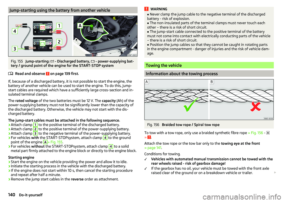
Jump-starting using the battery from another vehicleFig. 155
Jump-starting:
- Discharged battery,
- power-supplying bat-
tery / ground point of the engine for the START-STOP system
Read and observe
on page 139 first.
If, because of a discharged battery, it is not possible to start the engine, the
battery of another vehicle can be used to start the engine. To do this, jump-
start cables are required which have a sufficiently large cross-section and in-
sulated terminal clamps.
The rated voltage of the two batteries must be 12 V. The capacity (Ah) of the
power-supplying battery must not be significantly lower than the capacity of
the discharged battery. Otherwise, the vehicle may not start with the dis-
charged battery.
The jump-start cables must be attached in the following sequence.
›
Attach clamp
1
to the positive terminal of the discharged battery.
›
Attach clamp
2
to the positive terminal of the power-supplying battery.
›
Attach clamp
3
to the negative terminal of the power-supplying battery.
›
For vehicles with the START-STOPsystem, attach clamp
4
to the ground
point of the engine
A
» Fig. 155 .
›
For vehicles without the START-STOPsystem, attach clamp
4
to a solid
metal part firmly attached to the engine block or directly to the engine block.
Starting engine
›
Start the engine on the vehicle providing the power and allow it to idle.
›
Initiate the starting process in the vehicle with the discharged battery.
›
If the engine does not start within 10 s, then cancel the starting procedure
and repeat after half a minute.
›
Remove the jump start cables in the reverse order as attachment.
WARNING■
Never clamp the jump cable to the negative terminal of the discharged
battery - risk of explosion.■
The non-insulated parts of the terminal clamps must never touch each
other – there is a risk of short circuit.
■
The jump-start cable connected to the positive terminal of the battery
must not come into contact with electrically conducting parts of the vehicle
– there is a risk of short circuit.
■
Position the jump cables so that they cannot be caught in rotating parts
in the engine compartment - danger of injuries and the risk of vehicle dam-
age.
Towing the vehicle
Information about the towing process
Fig. 156
Braided tow rope / Spiral tow rope
To tow with a tow rope, only use a braided synthetic fibre rope » Fig. 156 -
»
.
Attach the tow rope or the tow bar only to the towing eye at the front
» page 141 .
Conditions for towing. Vehicles with automated manual transmission cannot be towed with the
rear wheels raised - risk of gearbox damage!
If the gearbox has no oil, your vehicle must be towed with the front axle
raised clear of the ground or on a breakdown vehicle or trailer.
140Do-it-yourself
Page 143 of 172
The maximum towing speed is 50 km/h.
The vehicle must be transported on a special breakdown vehicle or trailer
if it is not possible to tow in the vehicle in the way described or if the tow-
ing distance is greater than 50 km.
Driver of the towed vehicle›
If possible, the vehicle should be towed with the engine running. The brake
booster and power steering only operate if the engine is running, otherwise
much greater force has to be applied to the brake pedal and more power has
to be expended for steering.
›
If it is not possible to start the engine, switch on the ignition so that the
steering wheel does not lock and so that the turn signal lights, windscreen
wipers and windscreen washer system can be used.
›
Take the vehicle out of gear or move the selector lever into position N if the
vehicle is fitted with an automated transmission.
›
Keep the tow rope taut at all times during the towing procedure.
WARNING■ Spiral tow ropes must not be used for towing » Fig. 156- , the towing
eye may unscrew out of the vehicle - risk of accident.■
Ensure tow rope is not twisted - risk of accident.
CAUTION
■ Do not tow-start the engine – risk of damaging the engine! The battery from
another vehicle can be used as a jump-start aid » page 139, Jump-starting .■
For off-road towing manoeuvres, there is a risk to both vehicles that the fas-
teners may become overloaded and damaged.
Note
We recommend that you use a tow rope from ŠKODA Original Accessories.Front towing eyeFig. 157
Remove cap / install towing eye
Cap removal/fitting
›
To remove , press down on the cap in the direction of arrow
1
and remove it
in the direction of arrow
2
» Fig. 157 .
›
To fit it, insert the cap in arrow range
1
and then press on the opposite
edge of the cap. The cap must engage firmly.
Removing/fitting the towing eye
›
To fit, screw in the towing eye by hand in the direction of the arrow
3
» Fig. 157 until it clicks into place » .
For tightening purposes, we recommend, for example, using the wheel
wrench, towing eye from another vehicle or a similar object that can be pushed
through the eye.
›
To remove it, unscrew the towing eye in the opposite direction to arrow
3
.
WARNINGThe towing eye must always be firmly in place, otherwise the towing eye
could break whilst being towed.141Emergency equipment and self-help
Page 161 of 172
Gear changing38
In the instrument cluster37
Natural gas supply31
Service intervals42
Display MAXI DOT41
Disposal Acceptance and recycling of used vehicles
112
Door Child safety lock
45
Emergency locking142
Opening/Closing45
Door alarm37
Door opening lever Unlock / lock
44
Drive Driving through water
102
Driving Emissions
153
Fuel consumption153
through water102
Top speed156
Trailer operation112
E
Economical driving
102
EDL104
Electric windows46
Buttons in the driver door47
Electronic Differential Lock (EDL)104
Electronic immobiliser95
Emergency Hazard warning light system
52
Jump-starting139, 140
Towing the vehicle140
Tyre repair137
Unlocking / locking the door142
Emergency call90
Emergency equipment Jack133
Reflective vest133
Vehicle tool kit133
Warning triangle133
Emergency spare Removing / stowing
135
Emission control system35
Emissions153
Engine Running in
102
Engine compartment120
Brake fluid125
Coolant124
Engine oil123
Overview122
Vehicle battery126
Windscreen washer fluid123
Engine drag torque control (MSR)104
Engine number152
engine oil specification
123
Engine oil123
Check124
Oil changing123
Refilling124
Warning light33
EPC35
ESC Operation
104
Warning light34
Extended warranty6
External devices75
F
Fasteners
68
file formats media
88
Requirements and Restrictions88
Films115
Flashing50
FM82
Fog lights/rear fog light51
Foldable hook65
Footmats100
see footmats100
Force limiter Sliding/tilting roof
48
Front seats56
fuel Refuelling - natural gas
119
Fuel117
Fuel gauge31
Gas gauge31
refer to Fuel117
Refuelling118
Unleaded petrol118
Warning light35
Fuel consumption153
Fuel reserve35
Fuses144
Assignment of fuses on the side of the dash panel
146
in the dash panel145
in the engine compartment147
G
Gear changing Gear stick
99
Information on the selected gear38
Recommended gear38
Genuine parts111
H
Handbrake
98
Warning light32
Handbrake - automatic transmission Warning light
36
159Index
Page 162 of 172
Hazard warning light system52
HBA104
Headrests57
Heating71, 72
Mirrors55
Rear window53
Seats58
Help in an emergency10
HHC104
Hill Start Assist (HHC)104
Hook68
horn29
I
Ignition lock
96
immobiliser95
Important notes75
Importing phonebook91
In an emergency Changing a wheel
134
Inertia reels16
Information about the towing process140
Information service90
Information system37
Door alarm37
MAXI DOT display41
Service interval display42
Instrument cluster30
See instrument cluster30
Warning lights31
Interior light52
ISOFIX24, 25
J
Jack
133
- fit136
Jump-starting139, 140
K
Key Change battery
142
Lock43
Starting/Stopping the engine95
Unlock43
L
LEAVING HOME
51
lever Turn signal/main beam
50
Lever Cruise control
106
Operating the information system39
Windscreen wipers54
Lever operation100
light Flash
50
Fog lights/rear fog light51
Light Automatic driving light control
51
Cockpit52
COMING HOME / LEAVING HOME51
Dimmed headlights49
Headlight range control49
on and off49
Parking light52
Replacing bulbs147
Sidelights49
Turn signal/main beam50
Light bulbs Replacing
147
Lighting Interior lighting
52
Luggage compartment67
Light on and off49
Lights49
Abroad52
Daylight running50
Hazard warning light system52
Warning lights31
List of available stations
83
of telephone contacts91
With folder / track list84
List of paired Bluetooth devices93
Load153
Loading floor69
Lock Key
43
Locking Central locking button
44
in case of emergency142
Remote control43
locking the steering lock95
Low tyre pressure warning refer to the tyre pressure monitoring
108
Luggage compartment67
Cover69
Fasteners68
Fixing nets68
Hook68
Lighting67
unlock manually142
Unlock the boot lid142
Variable loading floor69
Luggage compartment cover69
Luggage compartment lid46
M
Main beam
50
Warning light36
Main menu Application management
94
Media84
Radio82
Managing paired Bluetooth devices93
160Index
Page 165 of 172
Blues radio radio menu80
Blues radio sound80
Link the application with Swing radio79
Radio volume77
Reset Blues radio to factory settings81
Reset Swing radio to factory settings79
safe removal of Blues radio data source81
Safe removal of the source from Swing radio79
Swing Bluetooth® radio79
Swing radio78
Swing radio language79
Swing radio menu media80
Swing radio Software update79
Swing radio system information79
Swing radio telephone78
Swing sound radio78
Swing system radio79
the Swing radio radio menu79
Setting the Clock
37
Sidelights49
Snow chains131
Socket 12-volt socket
63
Spare wheel130
Removing / stowing135
Speakerphone on / off92
Speed symbol131
Spoiler111
Stabilisation system103
Stability Control (ESC)104
START-STOP96
Jump-starting140
Manually deactivating/activating the system97
operation97
warning light36
START-STOP system96
Start engine96
Starting engine Jump-starting
139
Starting the engineJump-starting140
Status line Telephone
90
steering wheel Correct posture
13
Steering wheel setting
13
Stop engine96
Stopping see Parking
99
Storage59
Storage compartment in the front centre console
61
on the driver's side60
on the front passenger side64
with cover on the passenger side64
Storage compartments59
Stowage compartments in the doors
60
Stowage compartment on front of the rear seats
66
Sunblind for the tilt / slide sunroof49
Sun visors53
Supported sources media
88
Swing radio application connection
79
Bluetooth® settings79
Display settings79
Factory settings79
Media menu84
Media menu settings80
Menu application operation93
menu settings78
Phone menu88
Phone menu settings78
Radio menu81
Radio menu settings79
Safe removal of the source79
Settings78
Settings the device language79
Software update79
Sound settings78
status line77
System information79
System settings79
Swing Radio75
Device description76
Switch Car battery
127
Switch off the ignition96
Switch on ignition96
Switch telephone conversation To the device
92
To the phone92
T
TCS Operation
104
Warning light34
Technical data152
Telephone Call list
92
Conditions for pairing89
Main menu90
Operation90
Telephone90
Telephone book91
Telephone book91
The swing radio display76
Ticket holder60
Tilt / slide sunroof Activate operation
48
Operation48
Sunblind49
Time37
Tiptronic101
Tools133
163Index