engine coolant SKODA FABIA 2000 1.G / 6Y User Guide
[x] Cancel search | Manufacturer: SKODA, Model Year: 2000, Model line: FABIA, Model: SKODA FABIA 2000 1.G / 6YPages: 86, PDF Size: 3.58 MB
Page 33 of 86

Downloaded from www.Manualslib.com manuals search engine FABIA 2000➤Inspection and Maintenance
EnginesEdition 09.04
S00.5301.14.2002-3 page 13 02
♦Coolant additives complying with standard TL VW
774C (G11) -bluish-green in colour-, must only be
used for topping up on vehicles fitted with a cooling
system which is already filled with this coolant.
♦Vehicles produced as of MJ 03 are filled with coolant
additive G12 PLUS which has a lilac colour and con-
forms with the standard TL VW 774 F.
♦Coolant additive G12 PLUS must only be mixed with
coolant additives G12 and G11.
♦Coolant additive G12 PLUS is recommended for use
on all vehicles when changing the coolant.
Do not use coolant additives that have not been recom-
mended by ŠKODA AUTO a.s.
Other coolant additives may specifically impair the pro-
vided corrosion protection.
The resulting corrosion damage may lead to a loss of
coolant and subsequently cause major engine damage.
Coolant additives conforming to the standard TL VW 774
D (G12) or TL VW 774F (G12 PLUS) prevent frost and
corrosion damage, as well as the formation of scale, and
also increase the boiling point of the coolant.
For these reasons you must use coolant additives 12
months a year.
The engine's reliability is also increased when the engine
is stressed, especially in countries with a tropical climate.
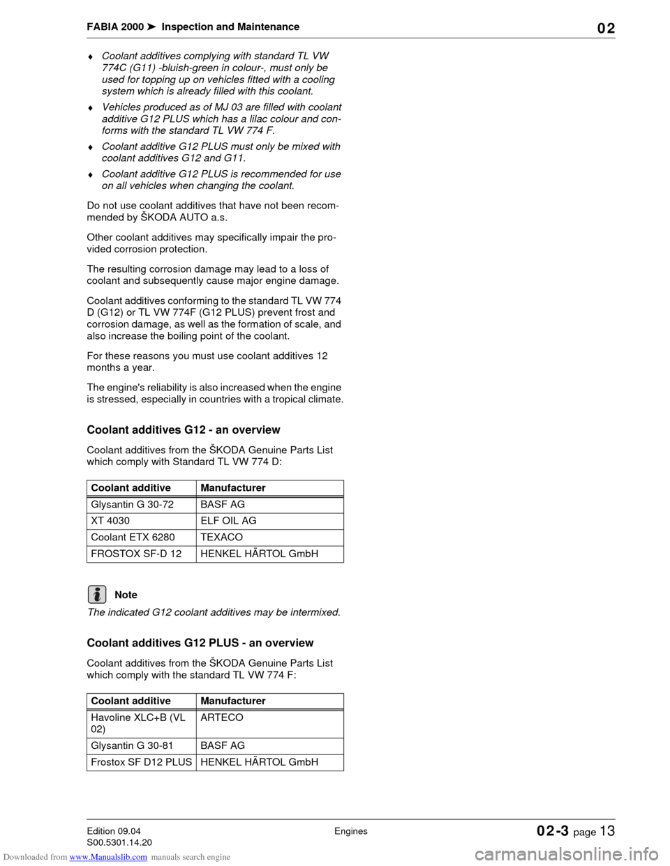
Coolant additives G12 - an overview
Coolant additives from the ŠKODA Genuine Parts List
which comply with Standard TL VW 774 D:
The indicated G12 coolant additives may be intermixed.
Coolant additives G12 PLUS - an overview
Coolant additives from the ŠKODA Genuine Parts List
which comply with the standard TL VW 774 F:Coolant additive Manufacturer
Glysantin G 30-72 BASF AG
XT 4030 ELF OIL AG
Coolant ETX 6280 TEXACO
FROSTOX SF-D 12 HENKEL HÄRTOL GmbH
Note
Coolant additive Manufacturer
Havoline XLC+B (VL
02)ARTECO
Glysantin G 30-81 BASF AG
Frostox SF D12 PLUS HENKEL HÄRTOL GmbH
Page 34 of 86

Downloaded from www.Manualslib.com manuals search engine FABIA 2000➤Inspection and Maintenance
EnginesEdition 09.04
S00.5301.14.2002-3 page 14 02
The listed G12 PLUS coolant additives may be inter-
mixed.
Ribbed V-belt: Inspect condition
Special tools, test and measuring equipment and
auxiliary items required
♦Wrench socket
Perform the following procedure:
–Raise vehicle.
–Remove bottom engine compartment cover at right.
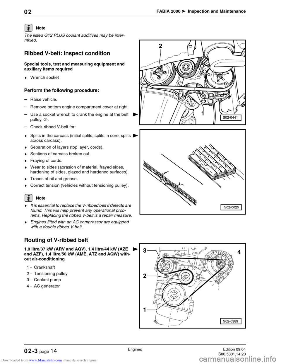
–Use a socket wrench to crank the engine at the belt
pulley -2-.
–Check ribbed V-belt for:
♦Splits in the carcass (initial splits, splits in core, splits
across carcass).
♦Separation of layers (top layer, cords).
♦Sections of carcass broken out.
♦Fraying of cords.
♦Wear to sides (abrasion of material, frayed sides,
hardening of sides, glazed and hardened surfaces).
♦Traces of oil and grease.
♦Correct tension (vehicles without tensioning pulley).
♦It is essential to replace the V-ribbed belt if defects are
found. This will help prevent any operational prob-
lems. Replacing the ribbed V-belt is a repair measure.
♦Engines fitted with an AC compressor are equipped
with a double ribbed V-belt.
Routing of V-ribbed belt
1.0 litre/37 kW (ARV and AQV), 1.4 litre/44 kW (AZE
and AZF), 1.4 litre/50 kW (AME, ATZ and AQW) with-
out air-conditioning
1 - Crankshaft
2 - Tensioning pulley
3 - Coolant pump
4 - AC generator
Note
S02-0025
Note
Page 35 of 86

Downloaded from www.Manualslib.com manuals search engine FABIA 2000➤Inspection and Maintenance
EnginesEdition 09.04
S00.5301.14.2002-3 page 15 02
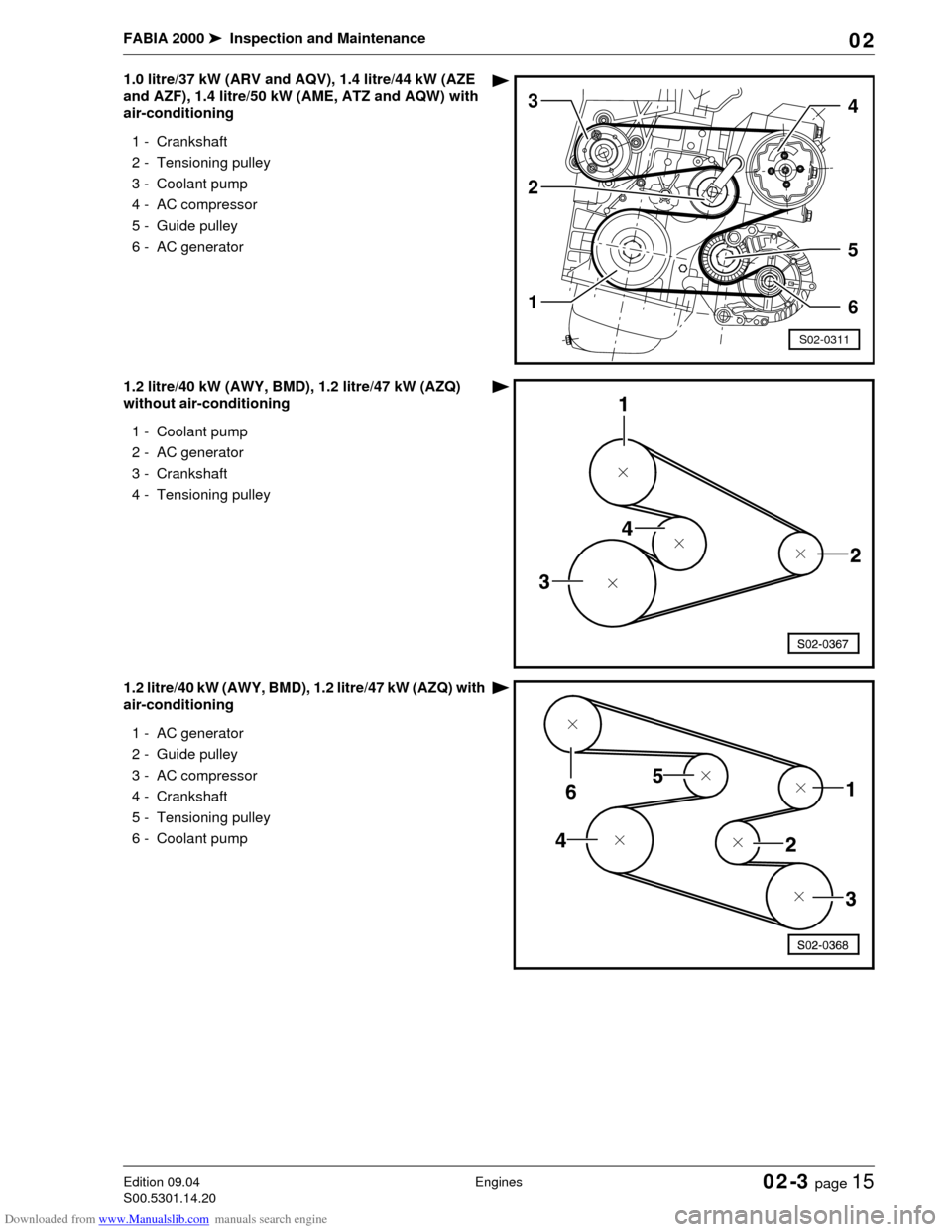
1.0 litre/37 kW (ARV and AQV), 1.4 litre/44 kW (AZE
and AZF), 1.4 litre/50 kW (AME, ATZ and AQW) with
air-conditioning
1 - Crankshaft
2 - Tensioning pulley
3 - Coolant pump
4- AC compressor
5 - Guide pulley
6 - AC generator
1.2 litre/40 kW (AWY, BMD), 1.2 litre/47 kW (AZQ)
without air-conditioning
1 - Coolant pump
2 - AC generator
3 - Crankshaft
4 - Tensioning pulley
1.2 litre/40 kW (AWY, BMD), 1.2 litre/47 kW (AZQ) with
air-conditioning
1 - AC generator
2 - Guide pulley
3- AC compressor
4 - Crankshaft
5 - Tensioning pulley
6 - Coolant pump
1
S02-0311
4
2
3
5
6
Page 38 of 86

Downloaded from www.Manualslib.com manuals search engine FABIA 2000➤Inspection and Maintenance
EnginesEdition 09.04
S00.5301.14.2002-3 page 18 02
Replace air filter element
–Open the filter housing.
–Replace the filter element and clean the filter housing.
–Close filter housing and check correct fitting.
Replacing the fuel filter (diesel engine)
♦Make sure no diesel fuel comes into contact with the
coolant hoses. If necessary clean the hoses immedi-
ately!
♦It is absolutely necessary to observe the oil disposal
instructions!
♦Observe the disposal instructions!
Removing
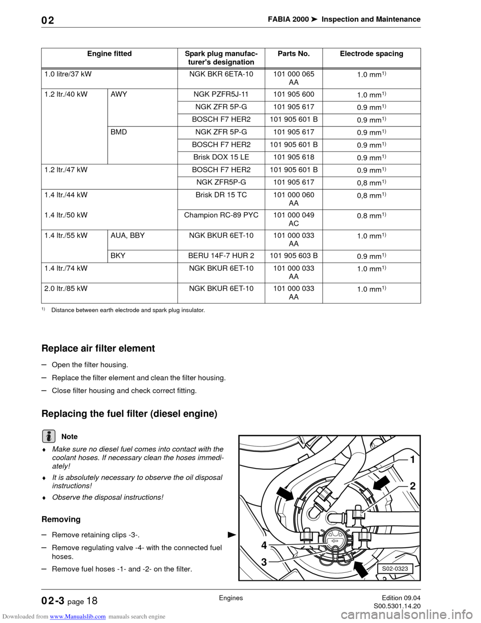
–Remove retaining clips -3-.
–Remove regulating valve -4- with the connected fuel
hoses.
–Remove fuel hoses -1- and -2- on the filter.Engine fitted Spark plug manufac-
turer's designationParts No. Electrode spacing
1.0 litre/37 kW NGK BKR 6ETA-10 101 000 065
AA1.0 mm
1)
1) Distance between earth electrode and spark plug insulator.
1.2 ltr./40 kW AWY NGK PZFR5J-11 101 905 600
1.0 mm1)
NGK ZFR 5P-G 101 905 617
0.9 mm1)
BOSCH F7 HER2 101 905 601 B
0.9 mm1)
BMD NGK ZFR 5P-G 101 905 617
0.9 mm1)
BOSCH F7 HER2 101 905 601 B
0.9 mm1)
Brisk DOX 15 LE 101 905 618
0.9 mm1)
1.2 ltr./47 kW BOSCH F7 HER2 101 905 601 B
0.9 mm1)
NGK ZFR5P-G 101 905 617
0,8 mm1)
1.4 ltr./44 kW Brisk DR 15 TC 101 000 060
AA0,8 mm1)
1.4 ltr./50 kW Champion RC-89 PYC 101 000 049
AC0.8 mm1)
1.4 ltr./55 kW AUA, BBY NGK BKUR 6ET-10 101 000 033
AA1.0 mm1)
BKY BERU 14F-7 HUR 2 101 905 603 B
0.9 mm1)
1.4 ltr./74 kW NGK BKUR 6ET-10 101 000 033
AA1.0 mm1)
2.0 ltr./85 kW NGK BKUR 6ET-10 101 000 033
AA1.0 mm1)
Note
1
2
3
4
S02-0323
Page 39 of 86

Downloaded from www.Manualslib.com manuals search engine FABIA 2000➤Inspection and Maintenance
EnginesEdition 09.04
S00.5301.14.2002-3 page 19 02
–Unlock hooks -arrows-.
–Loosen the fuel filter and remove.
Installing
–Install new fuel filter.
–Lock hooks -arrows-.
–Fit the new O-ring for the regulating valve.
–Install regulating valve -4- with the connected fuel
hoses.
–Attach retaining clips -3-.
–Install the fuel hoses -1- and -2- and secure with hose
clamps.
The direction of flow is indicated with arrows (do not
switch connections).
–Inspect the fuel system for tightness (visual inspec-
tion).
Draining the fuel filter (diesel engine)
♦Make sure no diesel fuel comes into contact with the
coolant hoses. If necessary clean the hoses immedi-
ately!
♦Collect fuel in a suitable vessel!
♦It is absolutely necessary to observe the oil disposal
instructions!
–Remove retaining clip -2- and remove regulating valve
-1- with the connected fuel hoses.
–Unlock hooks -arrows-.
–Loosen the fuel filter and remove.
Note
Note
S02-0324
1
2
1
2
3
4
S02-0323