Symbol SKODA FABIA 2004 1.G / 6Y User Guide
[x] Cancel search | Manufacturer: SKODA, Model Year: 2004, Model line: FABIA, Model: SKODA FABIA 2004 1.G / 6YPages: 247
Page 27 of 247
Instruments and Indicator/Warning Lights
26
One warning signal will sound if a yellow symbol appears.
If several operational faults of priority 2 exist, the symbols appear one after
the other and are each illiminated for about 2 seconds.
Check the relevant function as soon as possible.
Navigation system*
The controls for the navigation system, radio, CD player are located in the
centre console on both sides of the monitor screen. Navigation data is
also shown in the information display of the instrument cluster.
Information and warning texts are displayed preferentially when the navi-
gation system is switched on.
Operation of the navigation system is described in separate operating
instructions to be found in the on-board literature.
Page 29 of 247
Instruments and Indicator/Warning Lights
28
WARNING
•If you do not pay attention to the warning lights coming on and
the corresponding descriptions and warning notes, this may result
in severe body injuries or major vehicle damage.
•The engine compartment of your car is a hazardous area. There
is a risk of injuries, scalding, accid ents and fire when working in the
engine compartment, e.g. inspecting and replenishing oil and other
fluids. It is also essential to observe all warnings ⇒page 183.
Note
•Arrangement of the indicator lights depends on the model and model
version. The symbols shown in the following functional description are to
be found as indicator lights in the instrument cluster.
•Operational faults are shown in the instrument cluster as red symbols
(priority 1 - danger) or yellow symbols (priority 2 - warning).
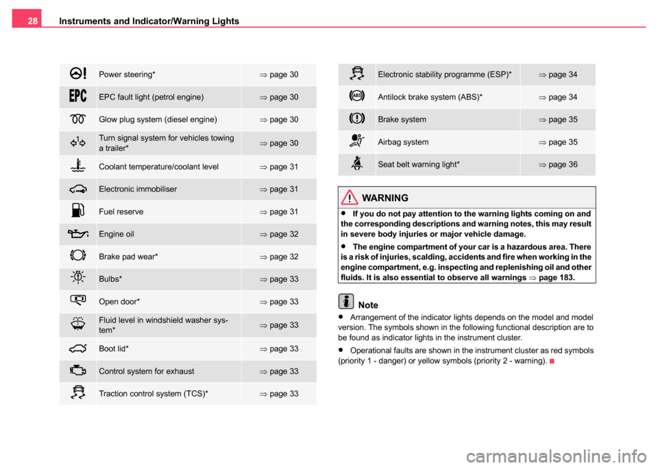
Power steering*⇒ page 30
EPC fault light (petrol engine)⇒page 30
Glow plug system (diesel engine)⇒page 30
Turn signal system for vehicles towing
a trailer*⇒page 30
Coolant temperature/coolant level⇒page 31
Electronic immobiliser⇒page 31
Fuel reserve⇒page 31
Engine oil⇒page 32
Brake pad wear*⇒page 32
Bulbs*⇒page 33
Open door*⇒page 33
Fluid level in windshield washer sys-
tem*⇒page 33
Boot lid*⇒page 33
Control system for exhaust⇒page 33
Traction control system (TCS)*⇒page 33
Electronic stability programme (ESP)*⇒page 34
Antilock brake system (ABS)*⇒page 34
Brake system⇒page 35
Airbag system⇒page 35
Seat belt warning light*⇒page 36
Page 40 of 247
Unlocking and locking39
Using the systemSafetyDriving TipsGeneral MaintenanceBreakdown assistanceTechnical Data
dealer. You should, however, proceed as follows if you wish to
replace the battery yourself:
– Fold open the key.
– Use a screwdriver to carefully lever off the front part of the key
⇒ page 38, fig. 19 from the transmitter housing .
– Take off the cover of the transmitter housing ⇒page 38,
fig. 20 in direction of arrow.
– Take the used battery out of the housing cover.
– Insert the new battery. Ensure that the “+” symbol on the battery is facing downwards. The correct polarity is also
shown on the cover of the transmitter housing.
– Insert cover with battery in place at the rear of the transmitter housing and press both parts together.
– Insert the transmitter housing into the front part of the key so that the two parts lock into each other.
For the sake of the environment
Dispose of an old battery in accordance with environmental regulations.
Note
•The replacement battery must have the same specification as the orig-
inal battery.
•If it is still not be possible to unlock or lock the vehicle with the remote
control even after replacing the battery this means that the system has to
be synchronised ⇒page 47.
Electronic immobiliser
The electronic immobiliser prevents the vehicle being
operated by an unauthorised person.
An electronic chip is integrated in the head of the key. The immobiliser is
deactivated with the aid of this chip when the key is inserted in the ignition
lock. The electronic immobiliser is automatically activated when you with-
draw the ignition key from the lock.
Note
It is only possible to start the engine of your car with a Genuine Škoda key
with the matching code ⇒page 31.
Locking
Valid for vehicles without a central locking system:
Locking from outside
The securing head will move upwards or downwards in the door when
unlocking or locking ⇒page 43, fig. 23 .
Locking from inside
All closed vehicle doors are locked by pressing in the securing knobs from
the inside. The doors cannot be opened from the outside when the
securing knobs have been pressed in. The vehicle doors can be opened
from the inside as follows:
•The door is unlocked by actuating the door-opening lever.
•The door opens upon actuating the door-opening lever again.
AAAB
AA
Page 55 of 247
Lights and Visibility
54
Lights and Visibility
Lights
Switching lights on and off
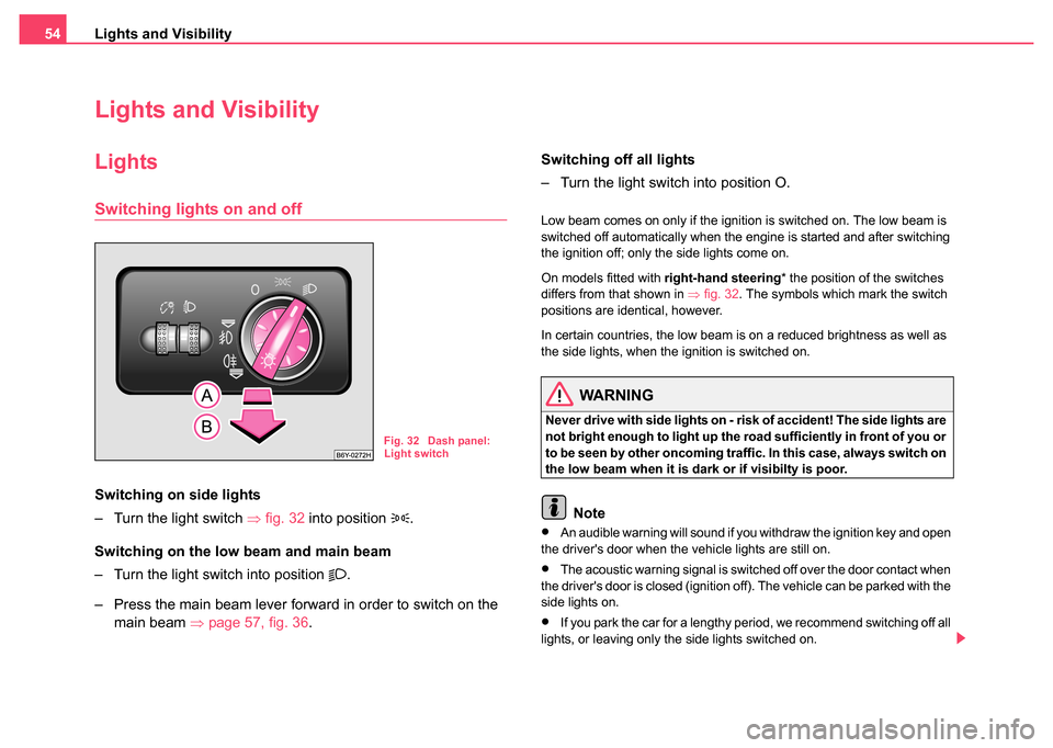
Switching on side lights
– Turn the light switch ⇒fig. 32 into position
.
Switching on the low beam and main beam
– Turn the light switch into position
.
– Press the main beam lever forward in order to switch on the main beam ⇒page 57, fig. 36 . Switching off all lights
– Turn the light switch into position O.
Low beam comes on only if the ignition is switched on. The low beam is
switched off automatically when the engine is started and after switching
the ignition off; only the side lights come on.
On models fitted with
right-hand steering* the position of the switches
differs from that shown in ⇒fig. 32 . The symbols which mark the switch
positions are identical, however.
In certain countries, the low beam is on a reduced brightness as well as
the side lights, when the ignition is switched on.
WARNING
Never drive with side lights on - ri sk of accident! The side lights are
not bright enough to light up the road sufficiently in front of you or
to be seen by other oncoming traffic. In this case, always switch on
the low beam when it is dark or if visibilty is poor.
Note
•An audible warning will sound if you withdraw the ignition key and open
the driver's door when the vehicle lights are still on.
•The acoustic warning signal is switched off over the door contact when
the driver's door is closed (ignition off). The vehicle can be parked with the
side lights on.
•If you park the car for a lengthy period, we recommend switching off all
lights, or leaving only the side lights switched on.
Fig. 32 Dash panel:
Light switch
Page 60 of 247
Lights and Visibility59
Using the systemSafetyDriving TipsGeneral MaintenanceBreakdown assistanceTechnical Data
– On the version without reading lights press the switch to
the right, the symbol O appears.
Reading lights
– Press on one of the switches ⇒page 58, fig. 37 in order to
switch the right or left reading light on or off.
Lighting of storage compar tment on the front passenger
side
– Open the flap of the storage compartment on the front passenger side.
– The light switches on automatically when the parking light is switched on and goes out when the flap is closed.
The interior light is switched on for about 20 seconds when a vehicle with
a central locking system is unlocked, when a door is opened or when the
ignition key is removed. The requirement for this is that the switch is in
the door contact position. The inner light goes out out immediately after
the ignition is switched on.
A time delay switch* causes the inner lighting on vehicles without a central
locking system stays on for a few seconds after the doors have been
closed. The inner light goes out out immediately after the ignition is
switched on.
The interior lighting is switched off after about 30 minutes when a door has
been left open in order to avoid discharging the battery of the vehicle.
Interior lighting at the r ear* (estate vehicle, sedan)
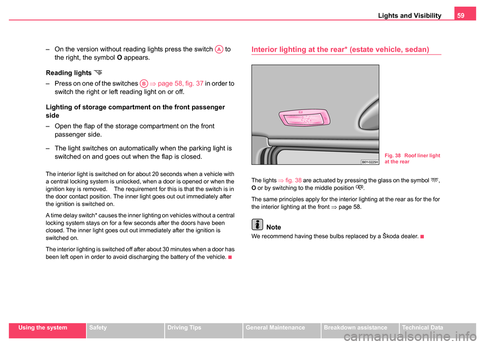
The lights ⇒fig. 38 are actuated by pressing the glass on the symbol ,
O or by switching to the middle position .
The same principles apply for the interior lighting at the rear as for the for
the interior lighting at the front ⇒ page 58.
Note
We recommend having these bulbs replaced by a Škoda dealer.
AA
AB
Fig. 38 Roof liner light
at the rear
Page 83 of 247

Seats and Stowage
82
Drinks can holder*
The drinks can holder is designed to place 0.33 litre drinks cans
in.
– Press on the symbol in the direction of
⇒ fig. 67 , the drinks
can holder slides out and opens up.
WARNING
The drinks can holder must always be closed when driving for
safety reasons.
Note holder
The note holder is designed for attaching a car park ticket in parking
areas.
The attached car park ticket must be removed before starting off in order
not to restrict the driver's vision.
Fig. 67 Dash panel:
Drinks can holderFig. 68 Windscreen:
Note holder
Page 93 of 247
Heating and air conditioning system
92
up. The risk of having an accident increases. Switch recirculated
air mode off as soon as the windows begin misting up.
Note
•The whole heat output will be needed to unfrost the windscreen and
side windows. No warm air will be fed to the footwell. This can lead to
restriction of the heating comfort.
•The used air streams out through the air removal openings in the
luggage compartment.
Set heating
Recommended settings of heating controls for:
Defrosting the windscreen and side windows
•Turn control dial ⇒page 91, fig. 84 to the right up to the stop
•Blower switch in position 4
•Turn the air distribution control into the position
•Close the air outlet vents 3
•Open air outlet vents 4 ⇒ page 93, fig. 85 and point towards the side
window.
Keeping windscreen and side windows demisted
We recommend that you use the following setting in cases where the
windows are misted up more than usual (e.g. when it is raining):
•Control dial where necessary to the heating range
•Blower switch in position 2 or 3
•Control dial to or as required or to any desired position
between these symbols
•Close the air outlet vents 3
•Open air outlet vents 4 and point towards the side window
Warming up the inside of the ve hicle as rapidly as possible
•Turn control dial to the right up to the stop
•Blower switch in position 4
•Turn the air distribution control into the position
•Open the air outlet vents 3 and 4
•We recommend pressing button air recirculation mode. The
windows can steam up in this position however.
Heating the vehicle to a comfortable temperature
We recommend the following setting once the windows are no longer
misted up and the desired teperature has been reached:
•Control dial at the desired heat output
•Blower switch in position 2 or 3
•Turn the air distribution control into the position
•Close the air outlet vents 3
•Open the air outlet vents 4
•Set the air distribution regulator as required between positions
and , if the windscreen gets misted up again.
Fresh air mode - ventilation
Non pre-warmed fresh air streams through the air inlet nozzles 3 and 4 for
the following settings.
Recirculated air mode must not be switched on.
•Turn the control dial ⇒page 91, fig. 84 to the left up to the stop
•Blower switch in the desired position
•Turn the air distribution control into the position
WARNING (continued)
AA
AB
AC
AA
AB
AC
AA
AB
AC
AD
AA
AB
AC
AC
AA
AB
AC
Page 94 of 247
Heating and air conditioning system 93
Using the systemSafetyDriving TipsGeneral MaintenanceBreakdown assistanceTechnical Data
•Open air outlet vents 3 and 4 ⇒ page 93, fig. 85
The control dial can be set to other positions as required.
Recirculated air mode
In recirculated air mode air is sucked out of the interior of
the vehicle and then fed back into the interior.
Recirculated air mode prevents polluted air outside the vehicle
from getting into the vehicle, for example when driving through a
tunnel or when standing in a traffic jam.
Switching recirculated air mode on
– Press button , the button symbol
lights up ⇒page 91,
fig. 84.
Switching recirculated air mode off
– Press button again, the button symbol
goes out.
The recirculated air mode is switched off automatically if the air distribu-
tion control is in position ⇒ page 91, fig. 84 .
WARNING
You should not leave recirculated air mode on over a longer period
of time. “Stale air” may result in fatigue in the driver and passen-
gers, reduce attention levels and also cause the windows to mist
up. The risk of having an accident increases. Switch recirculated
air mode off as soon as the windows begin misting up.
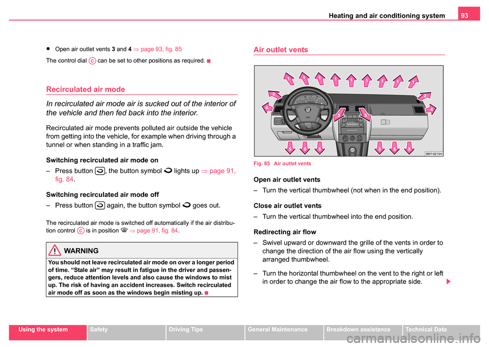
Air outlet vents
Fig. 85 Air outlet vents
Open air outlet vents
– Turn the vertical thumbwheel (not when in the end position).
Close air outlet vents
– Turn the vertical thumbwheel into the end position.
Redirecting air flow
– Swivel upward or downward the gr ille of the vents in order to
change the direction of the air flow using the vertically
arranged thumbwheel.
– Turn the horizontal thumbwheel on the vent to the right or left in order to change the air flow to the appropriate side.
AC
AC
Page 96 of 247
Heating and air conditioning system 95
Using the systemSafetyDriving TipsGeneral MaintenanceBreakdown assistanceTechnical Data
Note
We recommend that you do not smoke in the vehicle when the recircu-
lating air mode is operating since the smoke which is drawn at the evap-
orator from the interior of the vehicle forms deposits in the evaporator of
the air conditioning system. This produces a permanent odour when the
air conditioning system is operating which can only be eliminated through
considerable effort and expense (replacement of compressor).
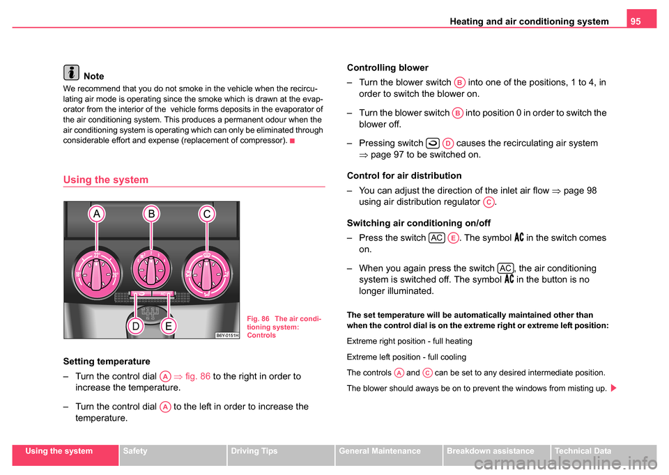
Using the system
Setting temperature
– Turn the control dial ⇒fig. 86 to the right in order to
increase the temperature.
– Turn the control dial to the left in order to increase the temperature. Controlling blower
– Turn the blower switch into one of the positions, 1 to 4, in
order to switch the blower on.
– Turn the blower switch into position 0 in order to switch the blower off.
– Pressing switch causes the recirculating air system ⇒page 97 to be switched on.
Control for air distribution
– You can adjust the direction of the inlet air flow ⇒page 98
using air distribution regulator .
Switching air conditioning on/off
– Press the switch . The symbol
in the switch comes
on.
– When you again press the switch , the air conditioning system is switched off. The symbol
in the button is no
longer illuminated.
The set temperature will be automatically maintained other than
when the control dial is on the extreme right or extreme left position:
Extreme right position - full heating
Extreme left position - full cooling
The controls and can be set to any desired intermediate position.
The blower should aways be on to prevent the windows from misting up.Fig. 86 The air condi-
tioning system:
Controls
AA
AA
AB
AB
AD
AC
ACAE
AC
AAAC
Page 98 of 247
Heating and air conditioning system 97
Using the systemSafetyDriving TipsGeneral MaintenanceBreakdown assistanceTechnical Data
•Open the air outlet vents 3 and 4
•Switch on the air conditioning system by pressing button
•Switch on recirculated air mode by pressing button .
•we recommend that you press the switch - recirculated air
mode - for a short time
Optimum cooling
•Control dial at the desired heat temperature. This temperature will
be maintained automatically.
•Blower switch in position 1, 2 , or 3
•Turn the air distribution control into the position
•Open the air outlet vents 3 and 4
•Switch on the air conditioning system by pressing button
•We recommend setting the air outlet vents 3 and 4 in such a way that
the air flows to the rear over the heads of the occupants. Do not press
button - recirculated air mode.
Fresh air mode (ventilation)
Non pre-warmed fresh air streams through the air inlet nozzles 3 and 4 for
the following settings.
•Turn the control dial ⇒page 95, fig. 86 to the left up to the stop
•Blower switch in the desired position
•Turn the air distribution control into the position
•Open air outlet vents 3 and 4 ⇒ page 98, fig. 87
•Switch off the recirculated air mode by pressing button .
•Switch off the cooling by pressing button
The control dial can be set to other positions as required.
Recirculated air mode
In recirculated air mode air is sucked out of the interior of
the vehicle and then fed back into the interior.
Recirculated air mode prevents polluted air outside the vehicle
from getting into the vehicle, for example when driving through a
tunnel or when standing in a traffic jam.
Switching recircul ated air mode on
– Press button ⇒ page 95, fig. 86, the button symbol
lights up.
Switching recirculated air mode off
– Press button again, the button symbol
goes out.
Recirculated air mode is switched off automatically if the air distribution
control is in position ⇒ page 95, fig. 86 . You can also switch recir-
culated air mode on again from this setting by repeatedly pressing button .
WARNING
You should not leave recirculated air mode on over a longer period
of time. “Stale air” may result in fatigue in the driver and passen-
gers, reduce attention levels and also cause the windows to mist
up. The risk of having an accident increases. Switch recirculated
air mode off as soon as the windows begin misting up.
AE
AD
AD
AA
AB
AC
AE
AD
AA
AB
AC
AD
AE
AC
AC
AD