engine coolant SKODA FABIA 2007 1.G / 6Y Owner's Manual
[x] Cancel search | Manufacturer: SKODA, Model Year: 2007, Model line: FABIA, Model: SKODA FABIA 2007 1.G / 6YPages: 242, PDF Size: 48.29 MB
Page 4 of 242
Contents3
Contents
Layout of this Owner's Manual
(explanations). . . . . . . . . . . . . . . . . . . . . . . . . .
Using the system. . . . . . . . . . . . . . . . . . . . . .
Cockpit. . . . . . . . . . . . . . . . . . . . . . . . . . . . . . . . . . . . . . . . General view . . . . . . . . . . . . . . . . . . . . . . . . . . . . . . . . .
Instruments and Indicator/Warning Lights. . . General view of the instrument cluster . . . . . . . . . Engine revolutions counter . . . . . . . . . . . . . . . . . . . . Coolant temperature gauge* . . . . . . . . . . . . . . . . . . Fuel gauge . . . . . . . . . . . . . . . . . . . . . . . . . . . . . . . . . . . Counter for distance driven . . . . . . . . . . . . . . . . . . . Service Interval Display . . . . . . . . . . . . . . . . . . . . . . . Digital clock . . . . . . . . . . . . . . . . . . . . . . . . . . . . . . . . . . Multi-functional indicato r (onboard computer)* Information display* . . . . . . . . . . . . . . . . . . . . . . . . . . Auto Check Control . . . . . . . . . . . . . . . . . . . . . . . . . . . Warning lights . . . . . . . . . . . . . . . . . . . . . . . . . . . . . . . .
Unlocking and locking . . . . . . . . . . . . . . . . . . . . . . . . Key . . . . . . . . . . . . . . . . . . . . . . . . . . . . . . . . . . . . . . . . . . Locking . . . . . . . . . . . . . . . . . . . . . . . . . . . . . . . . . . . . . . Child safety lock . . . . . . . . . . . . . . . . . . . . . . . . . . . . . . Central locking system* . . . . . . . . . . . . . . . . . . . . . . . Remote control* . . . . . . . . . . . . . . . . . . . . . . . . . . . . . . Anti-theft alarm system* . . . . . . . . . . . . . . . . . . . . . . Interior monitor* and Towing protection* . . . Power windows* . . . . . . . . . . . . . . . . . . . . . . . . . . . . . Electric sliding/tilting roof* . . . . . . . . . . . . . . . . . . . .
Lights and Visibility . . . . . . . . . . . . . . . . . . . . . . . . . . . Lights . . . . . . . . . . . . . . . . . . . . . . . . . . . . . . . . . . . . . . . . Interior lighting . . . . . . . . . . . . . . . . . . . . . . . . . . . . . . .
Visibility . . . . . . . . . . . . . . . . . . . . . . . . . . . . . . . . . . . . . Windshield wiper and wash system . . . . . . . . . . . . Rear mirror . . . . . . . . . . . . . . . . . . . . . . . . . . . . . . . . . .
Seats and Stowage. . . . . . . . . . . . . . . . . . . . . . . . . . . . Front seats . . . . . . . . . . . . . . . . . . . . . . . . . . . . . . . . . . . Head restraints . . . . . . . . . . . . . . . . . . . . . . . . . . . . . . . Heating the front seats* . . . . . . . . . . . . . . . . . . . . . . . Rear seats . . . . . . . . . . . . . . . . . . . . . . . . . . . . . . . . . . . . Pedals . . . . . . . . . . . . . . . . . . . . . . . . . . . . . . . . . . . . . . . luggage compartment . . . . . . . . . . . . . . . . . . . . . . . . The roof rack* . . . . . . . . . . . . . . . . . . . . . . . . . . . . . . . . Front cup holder . . . . . . . . . . . . . . . . . . . . . . . . . . . . . Rear cup holder* . . . . . . . . . . . . . . . . . . . . . . . . . . . . . Note holder . . . . . . . . . . . . . . . . . . . . . . . . . . . . . . . . . . Ashtray* . . . . . . . . . . . . . . . . . . . . . . . . . . . . . . . . . . . . . Cigarette lighter* and power sockets* . . . . . . . . . . Storage compartments . . . . . . . . . . . . . . . . . . . . . . . .
Heating and air conditioning system. . . . . . . . . Heating . . . . . . . . . . . . . . . . . . . . . . . . . . . . . . . . . . . . . . Climatic (semi-automatic air conditioning system)* . . . . . . . . . . . . . . . . . . . . . . . . . . . . . . . . . . . . . Climatronic (automatic air conditioning)* . . . . . .
Starting-off and Driving. . . . . . . . . . . . . . . . . . . . . . . Setting steering wheel position* . . . . . . . . . . . . . . . Ignition lock . . . . . . . . . . . . . . . . . . . . . . . . . . . . . . . . . . Starting the engine . . . . . . . . . . . . . . . . . . . . . . . . . . . Switching off the engine . . . . . . . . . . . . . . . . . . . . . . . Shifting (manual gearbox) . . . . . . . . . . . . . . . . . . . . . Handbrake . . . . . . . . . . . . . . . . . . . . . . . . . . . . . . . . . . . Parking aid* . . . . . . . . . . . . . . . . . . . . . . . . . . . . . . . . . . Cruise control system (CCS)* . . . . . . . . . . . . . . . . . .
Automatic gearbox . . . . . . . . . . . . . . . . . . . . . . . . . . . 6-speed automatic gearbox* . . . . . . . . . . . . . . . . . .
Communication . . . . . . . . . . . . . . . . . . . . . . . . . . . . . . Operating the radio . . . . . . . . . . . . . . . . . . . . . . . . . . . Radio and mobile phone operation . . . . . . . . . . . . Universal telephone preinstallation with voice control* . . . . . . . . . . . . . . . . . . . . . . . . . . . . . . . . . . . . . Inserting the mobile phone and adapter . . . . . . . Mobile phone operation . . . . . . . . . . . . . . . . . . . . . . Voice commands . . . . . . . . . . . . . . . . . . . . . . . . . . . . . Enter PIN code . . . . . . . . . . . . . . . . . . . . . . . . . . . . . . . Select number . . . . . . . . . . . . . . . . . . . . . . . . . . . . . . . Repeat last call . . . . . . . . . . . . . . . . . . . . . . . . . . . . . . . Phone voice phonebook* . . . . . . . . . . . . . . . . . . . . . Bluetooth™* . . . . . . . . . . . . . . . . . . . . . . . . . . . . . . . . . Mobile phones and two-way radio systems . . . . . Input AUX-IN* . . . . . . . . . . . . . . . . . . . . . . . . . . . . . . . CD changer* . . . . . . . . . . . . . . . . . . . . . . . . . . . . . . . . .
Safety . . . . . . . . . . . . . . . . . . . . . . . . . . . . . . . . . . . . . .
Passive Safety . . . . . . . . . . . . . . . . . . . . . . . . . . . . . . . . . Basic information . . . . . . . . . . . . . . . . . . . . . . . . . . . . Correct seated position . . . . . . . . . . . . . . . . . . . . . . .
Seat belts. . . . . . . . . . . . . . . . . . . . . . . . . . . . . . . . . . . . . . Why seat belts? . . . . . . . . . . . . . . . . . . . . . . . . . . . . . . The physical principle of a frontal collision . . . . . Important safety information regarding the use of seat belts . . . . . . . . . . . . . . . . . . . . . . . . . . . . . . . . . . . . How are seat belts correctly fastened? . . . . . . . . . Belt tensioner . . . . . . . . . . . . . . . . . . . . . . . . . . . . . . . .
Airbag system. . . . . . . . . . . . . . . . . . . . . . . . . . . . . . . . . Description of the airbag system . . . . . . . . . . . . . . . Front airbags . . . . . . . . . . . . . . . . . . . . . . . . . . . . . . . . . Side airbags* . . . . . . . . . . . . . . . . . . . . . . . . . . . . . . . . .
6
7
8 8
9 9 9101011111313161820
30 30 3232333739404043
45 45 49
51 5254
56 56 575859616164656666676768
75 75
77 81
86 86 87878989909091
94 94
99 99 100
101 102102103104105105106108109110110
113
113 113 115
118 118 119
119 120122
124 124 126128
NKO A05F 20 MR08.book Page 3 Thursday, April 19, 2007 11:34 AM
Page 10 of 242
Instruments and Indicator/Warning Lights9
Using the systemSafetyDriving TipsGeneral MaintenanceBreakdown assistanceTechnical Data
Instruments and Indicator/Warning Lights
General view of the instrument cluster
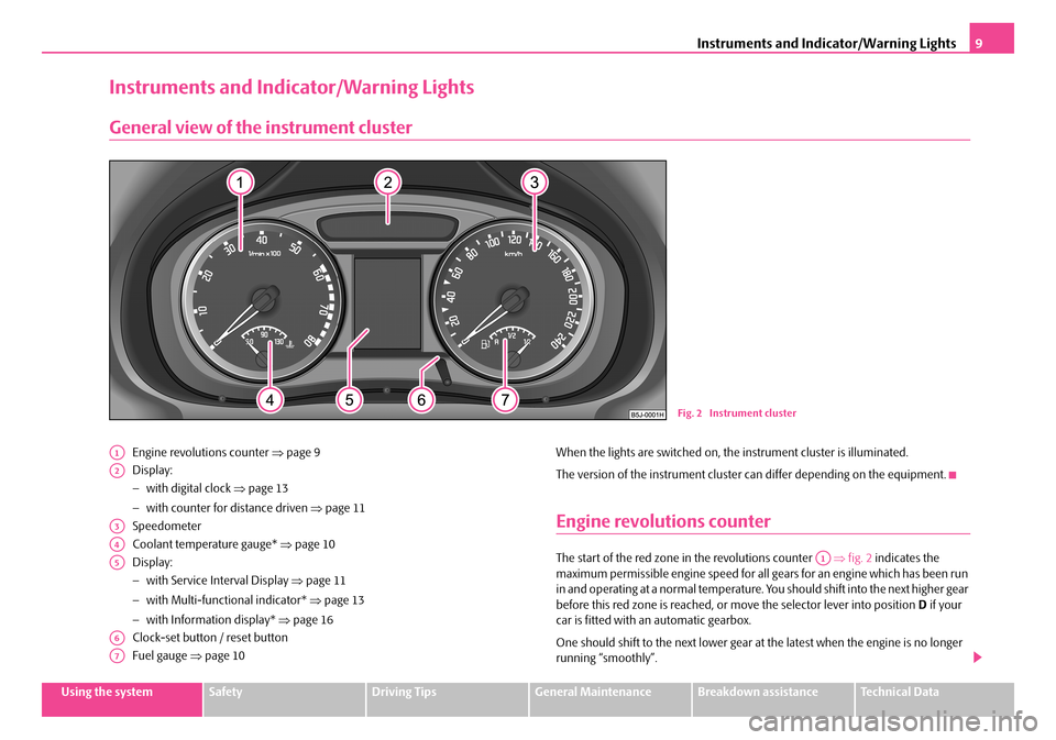
Engine revolutions counter ⇒page 9
Display:
− with digital clock ⇒page 13
− with counter for distance driven ⇒page 11
Speedometer
Coolant temperature gauge* ⇒page 10
Display:
− with Service Interval Display ⇒page 11
− with Multi-functional indicator* ⇒page 13
− with Information display* ⇒page 16
Clock-set button / reset button
Fuel gauge ⇒page 10
When the lights are switched on, the instrument cluster is illuminated.
The version of the instrument cluster can differ depending on the equipment.
Engine revolutions counter
The start of the red zone in the revolutions counter ⇒fig. 2 indicates the maximum permissible engine speed for all gears for an engine which has been run in and operating at a normal temperature. Yo u should shift into the next higher gear before this red zone is reached, or move the selector lever into position D if your car is fitted with an automatic gearbox.
One should shift to the next lower gear at the latest when the engine is no longer running “smoothly”.
Fig. 2 Instrument cluster
A1
A2
A3
A4
A5
A6
A7
A1
NKO A05F 20 MR08.book Page 9 Thursday, April 19, 2007 11:34 AM
Page 11 of 242

Instruments and Indicator/Warning Lights10
Avoid high engine speeds during the running-in period ⇒page 151.
Caution
The needle of the revolutions counter must on no account move into the red zone of the scale - risk of engine damage!
For the sake of the environment
Shifting up early helps you save fuel and reduce the operating noise of your vehicle.
Coolant temperature gauge*
The coolant temperature gauge ⇒page 9, fig. 2 operates only when the ignition is switched on.
In order to avoid any damage to the engine , please pay attention to the following notes regarding the temperature ranges:
Cold range
If the pointer is in the left-hand area of the scale* it means that the engine has not yet reached its operating temperature. Avoid running at high engine speeds, at full throttle and at severe engine loads.
The operating range
The engine has reached its operating temperature as soon as the pointer moves into the mid-range of the scale*. The pointe r may also move further to the right at high engine loads and high outside temperat ures. This is not critical provided the warning symbol in the instrument cluster does not flash.
If the symbol in the instrument cluster flashes it means that either the coolant temperature is too high or the coolant level is too low. Please refer to the guide- lines ⇒page 24, “Coolant temperature/coolant level ”.
WARNING
Pay attention to the warning notes ⇒page 173, “Working in the engine compartment” before opening the bonnet and inspecting the coolant level.
Caution
Additional headlights and other attached co mponents in front of the fresh air inlet impair the cooling efficiency of the coolant. There is then a risk of the engine over-heating at high outside temperatures and high engine loads!
Fuel gauge
The fuel gauge ⇒page 9, fig. 2 only operates when the ignition is switched on.
The fuel tank has a capacity of about 45 litres. The warning symbol in the instru- ment cluster lights up when the pointer reaches the reserve marking. There are now about 7 litres of fuel remaining in the tank. This symbol is a reminder for you, that you must refuel .
The following will be displayed in the information display*:
PLEASE REFUEL
A peep sounds as an additional warning signal.
Caution
Never run the fuel tank completely empty! An irregular fuel supply can result in poor ignition or misfiring. Unburnt fuel may get into the exhaust system and damage the catalytic converter.
A4A7
NKO A05F 20 MR08.book Page 10 Thursday, April 19, 2007 11:34 AM
Page 20 of 242
Instruments and Indicator/Warning Lights19
Using the systemSafetyDriving TipsGeneral MaintenanceBreakdown assistanceTechnical Data
There is at least one error message to be read when the term VEH. STATUS is flashing in the main menu. The display will show STATUS 1/2 (for example) if a number of error messages are displayed. This display indicates that the first of a total of two error messages should be displayed.
Actuate the rocker switch , to call up the individual error messages.
If a fault occurs, a warning signal will also sound in addition to the symbol and text in the display:
•Priority 1 - three warning signals,
•Priority 2 - one warning signal.
Red symbols
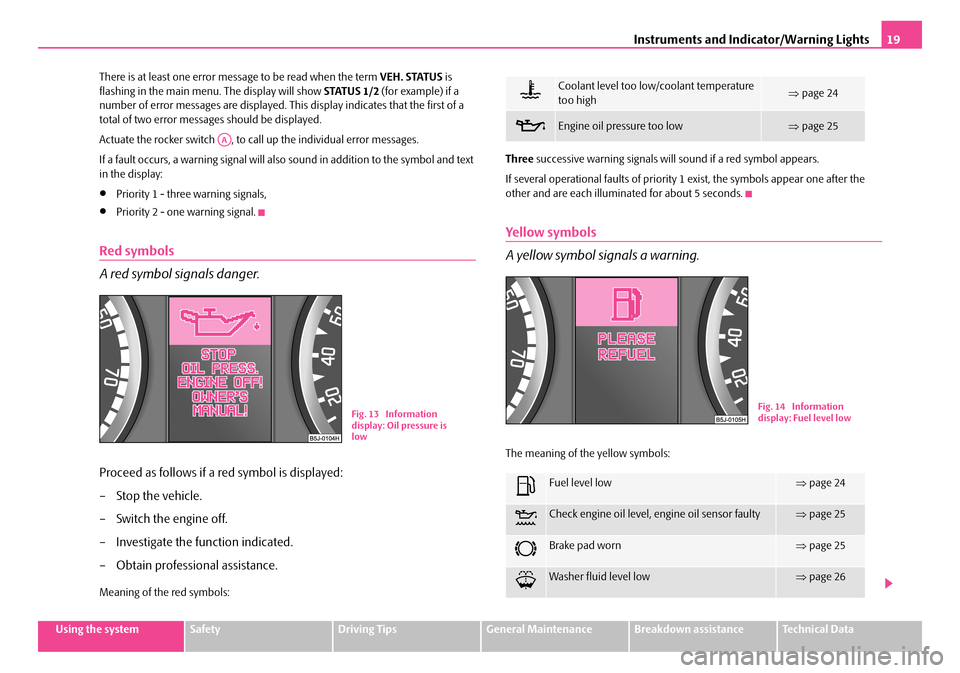
A red symbol signals danger.
Proceed as follows if a red symbol is displayed:
– Stop the vehicle.
– Switch the engine off.
– Investigate the function indicated.
– Obtain professional assistance.
Meaning of the red symbols:
Three successive warning signals will sound if a red symbol appears.
If several operational faults of priority 1 exist, the symbols appear one after the other and are each illumi nated for about 5 seconds.
Yellow symbols
A yellow symbol si gnals a warning.
The meaning of the yellow symbols:
AA
Fig. 13 Information display: Oil pressure is low
Coolant level too low/coolant temperature too high⇒ page 24
Engine oil pressure too low ⇒page 25
Fuel level low⇒page 24
Check engine oil level, engine oil sensor faulty⇒page 25
Brake pad worn⇒page 25
Washer fluid level low⇒page 26
Fig. 14 Information display: Fuel level low
NKO A05F 20 MR08.book Page 19 Thursday, April 19, 2007 11:34 AM
Page 22 of 242
Instruments and Indicator/Warning Lights21
Using the systemSafetyDriving TipsGeneral MaintenanceBreakdown assistanceTechnical Data
WARNING
•If you do not pay attention to the warning lights coming on and the corre- sponding descriptions and warning notes, this may result in severe body injuries or major vehicle damage.
•The engine compartment of your car is a hazardous area. There is a risk of injuries, scalding, accidents and fire when working in the engine
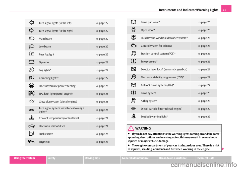
Turn signal lights (to the left)⇒page 22
Turn signal lights (to the right)⇒page 22
Main beam⇒page 22
Low beam⇒page 22
Rear fog light⇒page 22
Dynamo⇒page 22
Fog lights*⇒page 22
Cornering lights*⇒page 22
Electrohydraulic power steering⇒page 23
EPC fault light (petrol engine)⇒page 23
Glow plug system (diesel engine)⇒page 23
Turn signal system for vehicles towing a trailer*⇒ page 23
Coolant temperature/coolant level⇒page 24
Electronic immobiliser⇒page 24
Fuel reserve⇒page 24
Engine oil⇒page 25
Brake pad wear*⇒page 25
Open door*⇒page 25
Fluid level in windshield washer system*⇒page 26
Control system for exhaust⇒page 26
Tra c t i o n c o n t r o l s y s t e m ( TC S ) *⇒page 26
Tyre pressure*⇒page 26
Selector lever lock* (automatic gearbox)⇒page 27
Electronic stability programme (ESP)*⇒page 27
Antilock brake system (ABS)*⇒page 27
Brake system⇒page 28
Airbag system⇒page 28
Diesel particle filter* (diesel engine)⇒page 29
Seat belt warning light*⇒page 29
NKO A05F 20 MR08.book Page 21 Thursday, April 19, 2007 11:34 AM
Page 25 of 242

Instruments and Indicator/Warning Lights24
The indicator light does not flash if a turn signal light on the trailer or on the vehicle is not operating.
Coolant temperature/coolant level
The warning light comes on for a few seconds 1) when the ignition is switched on.
The coolant temperature is too high or the coolant level too low if the warning light does not go out after the engine is started or flashes while driving.
3 peeps sound as an additional warning signal.
In this case stop and switch the engine off and check the coolant level; top up the coolant as necessary ⇒page 179, “Replenishing the coolant”.
Do not continue your journey if for some reason it is not possible under the conditions prevailing to top up with coolant. Keep the engine switched off and obtain professional assistance from a specialist garage, otherwise it could lead to severe engine damage.
If the coolant is within the specified range, the increased temperature may be caused by an operating problem at the coolant fan. Check the fuse for the coolant fan, replace it if necessary ⇒page 208, “Fuse assignment at battery”.
Do not continue driving if the warning light does not go off although the fluid is at the correct level and also the fuse of the fa n is in proper order. Contact a specialist garage to obtain assistance.
Please also refer to the additional instructions ⇒page 177, “Cooling system”.
The following text will be displayed in the information display*:
STOP CHECK COOLANT OWNER'S MANUAL!
WARNING
•If you must stop for technical reasons, then park the vehicle at a safe distance from the traffic and switch off the engine and switch on the hazard warning light system ⇒page 48, “Switch for hazard warning lights ”.
•Pay attention to the following instructions ⇒page 173, “Working in the engine compartment” before checking the coolant fluid level and opening the bonnet.
•Take care when opening the coolant expa nsion bottle. If the engine is hot, the cooling system is pressurized - risk of scalding. It is best to allow the engine to cool down before removing the cap.
•Do not touch the coolant fan! The coolant fan may switch on automati- cally even if the ignition is off.
Electronic immobiliser
Data is compared between the ignition ke y and the control unit when switching on the ignition. The indicator light will light up for a few seconds when ignition key authorisation is confirmed.
The warning light will start flashing conti nuously if a non-authorised ignition key (for example the wrong ignition key) has been used. The engine cannot be started ⇒ page 31.
It is only possible to start the engine of your car with a Genuine Škoda key with the matching code.
Fuel reserve
The warning light comes on, if the fuel level is still about 7 litres.
A peep sounds as an additional warning signal.
The following text will be displayed in the information display*:
PLEASE REFUEL1)The warning light on vehicles fitted with information display does not come on after switching the ignition on, but only if the coolant temperature is too high or the coolant levelis too low.
NKO A05F 20 MR08.book Page 24 Thursday, April 19, 2007 11:34 AM
Page 26 of 242
Instruments and Indicator/Warning Lights25
Using the systemSafetyDriving TipsGeneral MaintenanceBreakdown assistanceTechnical Data
Engine oil
The warning light lights up red (low oil pressure)
The warning light comes on for a few seconds 2) when the ignition is switched on.
Stop the vehicle and switch the engine off if the warning light does not go off after the engine has started or flashes while driving. Check the oil level and top up with oil as necessary ⇒page 176.
3 peeps sound as an additional warning signal.
Do not continue your journey if for some reason it is not possible under the conditions prevailing to top up with oil. Keep the engine switched off and obtain professional assistance from a specialist garage, otherwise it could lead to severe engine damage.
Do not drive any further if the warning light flashes even if the oil is at the correct level. Do not run the engine not at idling speed either. Contact the nearest specialist garage to obtain professional assistance.
The following text will be displayed in the information display*:
STOP OIL PRESS. ENGINE OFF! OWNER'S MANUAL!
The warning light lights up yellow* (oil quantity too low)
If the warning light lights up yellow, the quan tity of oil in the engine is probably too low. Check as soon as possible the oil level or top up ⇒page 176 with engine oil.
A peep sounds as an addi tional warning signal.
The following text will be displayed in the information display*:
CHECK OIL LEVEL
The warning light will go out if the bonnet is left open for more than 30 seconds. If no engine oil has been replenished, the warning light will come on again after driving about 100 km.
The warning light flashes yellow* (engine oil level sensor faulty)
A fault on the engine oil level sensor is in dicated additionally by an audible signal and the warning light coming on several ti mes after the ignition has been switched on.
In this case have the engine inspecte d without delay by a specialist garage.
The following text will be displayed in the information display*:
OIL SENSOR WORKSHOP!
WARNING
•If you must stop for technical reasons, then park the vehicle at a safe distance from the traffic and switch off the engine and switch on the hazard warning light system ⇒page 48.
•The red oil pressure light is not an oil level indicator! One should therefore check the oil level at regular intervals, preferably after every refu- eling stop.
•Pay attention to the following instructions ⇒page 173, “Working in the engine compartment” before checking the coolant fluid level and opening the bonnet.
Thickness of the brake pads*
If the warning light comes on, contact a specialist garage immediately and have the brake pads on all of the wheels inspected.
A peep sounds as an ad ditional warning signal.
The following text will be displayed in the information display*:
CHECK BRAKE PAD
Open door*
The warning light comes on if one or several doors, the bonnet or boot lid is opened.2)The warning light on vehicles fitted with information display does not come on after switching the ignition on, but only if a fault exists or the engine oil level is too low.
NKO A05F 20 MR08.book Page 25 Thursday, April 19, 2007 11:34 AM
Page 76 of 242
Heating and air conditioning system75
Using the systemSafetyDriving TipsGeneral MaintenanceBreakdown assistanceTechnical Data
Heating and air conditioning system
Heating
Using the system
The heating system delivers air into the interior of the vehicle and
warms it as required.
Setting temperature
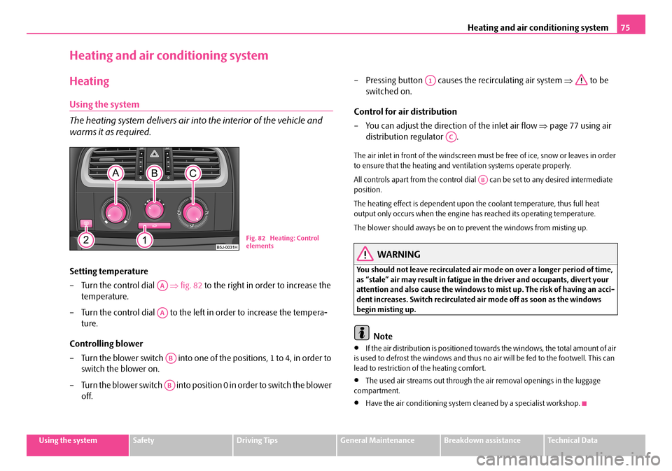
– Turn the control dial ⇒fig. 82 to the right in order to increase the
temperature.
– Turn the control dial to the left in order to increase the tempera-
ture.
Controlling blower
– Turn the blower switch into one of the positions, 1 to 4, in order to
switch the blower on.
– Turn the blower switch into position 0 in order to switch the blower
off.
– Pressing button causes the recirculating air system ⇒ to be
switched on.
Control for air distribution
– You can adjust the direction of the inlet air flow ⇒page 77 using air
distribution regulator .
The air inlet in front of the windscreen must be free of ice, snow or leaves in order to ensure that the heating and ventilation systems operate properly.
All controls apart from the control dial can be set to any desired intermediate position.
The heating effect is dependent upon th e coolant temperature, thus full heat output only occurs when the engine has reached its operating temperature.
The blower should aways be on to prevent the windows from misting up.
WARNING
You should not leave recirculated air mode on over a longer period of time, as “stale” air may result in fatigue in the driver and occupants, divert your attention and also cause the windows to mist up. The risk of having an acci- dent increases. Switch recirculated air mode off as soon as the windows begin misting up.
Note
•If the air distribution is positioned towa rds the windows, the total amount of air is used to defrost the window s and thus no air will be fed to the footwell. This can lead to restriction of the heating comfort.
•The used air streams out through the air removal openings in the luggage compartment.
•Have the air conditioning system cleaned by a specialist workshop.
Fig. 82 Heating: Control elements
AA
AA
AB
AB
A1
AC
AB
NKO A05F 20 MR08.book Page 75 Thursday, April 19, 2007 11:34 AM
Page 78 of 242
Heating and air conditioning system77
Using the systemSafetyDriving TipsGeneral MaintenanceBreakdown assistanceTechnical Data
WARNING
You should not leave recirculated air mode on over a longer period of time, as “stale” air may result in fatigue in the driver and occupants, divert your attention and also cause the windows to mist up. The risk of having an acci- dent increases. Switch recirculated air mode off as soon as the windows begin misting up.
Air outlet vents
Fig. 83 Air outlet vents
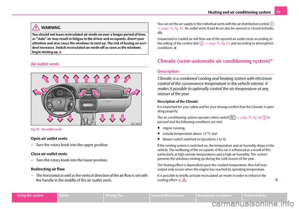
Open air outlet vents
– Turn the rotary knob in to the upper position.
Close air outlet vents
– Turn the rotary knob into the lower position.
Redirecting air flow
– The horizontal as well as the vertical direction of the air flow is set with
the handle in the middle of the air outlet vents.
You can set the air supply to the individual vents with the air distribution control ⇒ page 75, fig. 82. Air outlet vents 3 and 4 can also be opened or closed individu- ally.
Unwarmed or cooled air will flow out of the opened air outlet vents according to the setting of the control dial ⇒page 75, fig. 82 and according to atmospheric conditions.
Climatic (semi-automatic air conditioning system)*
Description
Climatic is a combined cooling and heating system with electronic
control of the convenience temperat ure in the vehicle interior. It
makes it possible to optimally control the air temperature at any
season of the year.
Description of the Climatic
It is important for your safety and for your driving comfort that the Climatic is oper- ating properly.
The air conditioning system operates when switch ⇒page 78, fig. 84 is pressed and the following conditions are met:
•engine running,
•outside temperature above +2 °C and
•blower switch switched on (positions 1 to 4).
If the cooling system is switched on, th e temperature and air humidity drops in the vehicle. The wellbeing of the occupants of the car is enhanced as a result of this particularly at high outside temperatur es and a high air humidity. The system prevents the windows misting up during the cold season of the year.
The heating effect is dependent upon th e coolant temperature, thus full heat output only occurs when the engine has reached its operating temperature.
It is possible to briefly activate recirc ulated air mode in order to enhance the cooling effect ⇒.
AC
AA
ACAE
NKO A05F 20 MR08.book Page 77 Thursday, April 19, 2007 11:34 AM
Page 82 of 242
Heating and air conditioning system81
Using the systemSafetyDriving TipsGeneral MaintenanceBreakdown assistanceTechnical Data
Close air outlet vents
– Turn the rotary knob into the lower position.
Redirecting air flow
– The horizontal as well as the vertical direction of the air flow is set with
the handle in the middle of the air outlet vents.
You can set the air supply to the individual vents with the air distribution control ⇒ page 78, fig. 84. Air outlet vents 3 and 4 can also be opened or closed individu- ally:
Unwarmed or cooled air will flow out of th e air outlet vents according to the setting of control dial ⇒page 78, fig. 84 and the atmospheric conditions.
Using the air conditioning system economically
The compressor on the Climatic uses power from the engine when in cooling mode which will effect the fuel consumption.
It recommended to open the windows or th e doors of a vehicle for which the inte- rior has been strongly heated through the ef fect of direct sunlight in order to allow the heated air to escape.
The cooling system should not be switched on while travelling when the window is open.
The desired interior temperature can also be achieved without switching in the cooling system just by switching to fresh air mode.
For the sake of the environment
When you economize on fuel, you also reduce pollutant emissions.
Operational problems
If the cooling system does not operate at outside temperatures higher than +2 °C, there is a problem in the system. The reasons for this may be:
•The fuse of the Climatic is defective. Check the fuse, replace it if necessary ⇒ page 205.
•The cooling system has switched off automatically for a short time because the coolant temperature of the engine is too hot ⇒page 10.
If you are not able to rectify the operat ional problem yourself, or if the cooling capacity decreases, switch the cooling sy stem off. Contact a specialist garage.
If there is a fault at the Climatronic, all symbols on the display flash after switching on the ignition for 15 seconds. Contact a specialist garage.
Climatronic (automatic air conditioning)*
Description
The Climatronic system is a comb ination of an automatic heating,
fresh air and cooling system which provides optimal comfort for the
occupants of the car.
The Climatronic maintains a constant temper ature fully automatically, once it has been set. This is achieved by automa tically varying the temperature of the outflowing air, the blower stages and the ai r distribution. The system also takes into account sunlight which eliminates the n eed to alter the settings manually. The automatic mode ⇒page 83 ensures maximum wellbeing of the occupants at all times of the year.
Description of Climatronic system
The cooling operates only if the following conditions are met:
•engine running,
•outside temperature above +2 °C,
•the button is not pressed.
If the cooling system is switched on, th e temperature and air humidity drops in the vehicle. The wellbeing of the occupants of the car is enhanced as a result of this particularly at high outside temperatur es and a high air humidity. The system prevents the windows misting up during the cold season of the year.
AC
AA
ECON
NKO A05F 20 MR08.book Page 81 Thursday, April 19, 2007 11:34 AM