service indicator SKODA FABIA 2007 1.G / 6Y Owner's Manual
[x] Cancel search | Manufacturer: SKODA, Model Year: 2007, Model line: FABIA, Model: SKODA FABIA 2007 1.G / 6YPages: 242, PDF Size: 48.29 MB
Page 4 of 242
Contents3
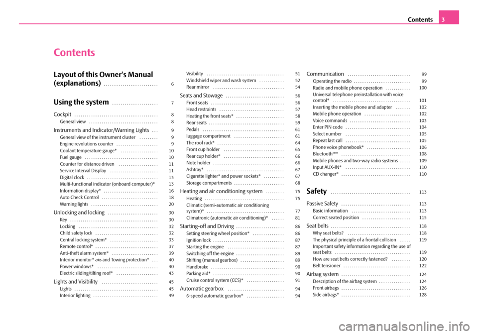
Contents
Layout of this Owner's Manual
(explanations). . . . . . . . . . . . . . . . . . . . . . . . . .
Using the system. . . . . . . . . . . . . . . . . . . . . .
Cockpit. . . . . . . . . . . . . . . . . . . . . . . . . . . . . . . . . . . . . . . . General view . . . . . . . . . . . . . . . . . . . . . . . . . . . . . . . . .
Instruments and Indicator/Warning Lights. . . General view of the instrument cluster . . . . . . . . . Engine revolutions counter . . . . . . . . . . . . . . . . . . . . Coolant temperature gauge* . . . . . . . . . . . . . . . . . . Fuel gauge . . . . . . . . . . . . . . . . . . . . . . . . . . . . . . . . . . . Counter for distance driven . . . . . . . . . . . . . . . . . . . Service Interval Display . . . . . . . . . . . . . . . . . . . . . . . Digital clock . . . . . . . . . . . . . . . . . . . . . . . . . . . . . . . . . . Multi-functional indicato r (onboard computer)* Information display* . . . . . . . . . . . . . . . . . . . . . . . . . . Auto Check Control . . . . . . . . . . . . . . . . . . . . . . . . . . . Warning lights . . . . . . . . . . . . . . . . . . . . . . . . . . . . . . . .
Unlocking and locking . . . . . . . . . . . . . . . . . . . . . . . . Key . . . . . . . . . . . . . . . . . . . . . . . . . . . . . . . . . . . . . . . . . . Locking . . . . . . . . . . . . . . . . . . . . . . . . . . . . . . . . . . . . . . Child safety lock . . . . . . . . . . . . . . . . . . . . . . . . . . . . . . Central locking system* . . . . . . . . . . . . . . . . . . . . . . . Remote control* . . . . . . . . . . . . . . . . . . . . . . . . . . . . . . Anti-theft alarm system* . . . . . . . . . . . . . . . . . . . . . . Interior monitor* and Towing protection* . . . Power windows* . . . . . . . . . . . . . . . . . . . . . . . . . . . . . Electric sliding/tilting roof* . . . . . . . . . . . . . . . . . . . .
Lights and Visibility . . . . . . . . . . . . . . . . . . . . . . . . . . . Lights . . . . . . . . . . . . . . . . . . . . . . . . . . . . . . . . . . . . . . . . Interior lighting . . . . . . . . . . . . . . . . . . . . . . . . . . . . . . .
Visibility . . . . . . . . . . . . . . . . . . . . . . . . . . . . . . . . . . . . . Windshield wiper and wash system . . . . . . . . . . . . Rear mirror . . . . . . . . . . . . . . . . . . . . . . . . . . . . . . . . . .
Seats and Stowage. . . . . . . . . . . . . . . . . . . . . . . . . . . . Front seats . . . . . . . . . . . . . . . . . . . . . . . . . . . . . . . . . . . Head restraints . . . . . . . . . . . . . . . . . . . . . . . . . . . . . . . Heating the front seats* . . . . . . . . . . . . . . . . . . . . . . . Rear seats . . . . . . . . . . . . . . . . . . . . . . . . . . . . . . . . . . . . Pedals . . . . . . . . . . . . . . . . . . . . . . . . . . . . . . . . . . . . . . . luggage compartment . . . . . . . . . . . . . . . . . . . . . . . . The roof rack* . . . . . . . . . . . . . . . . . . . . . . . . . . . . . . . . Front cup holder . . . . . . . . . . . . . . . . . . . . . . . . . . . . . Rear cup holder* . . . . . . . . . . . . . . . . . . . . . . . . . . . . . Note holder . . . . . . . . . . . . . . . . . . . . . . . . . . . . . . . . . . Ashtray* . . . . . . . . . . . . . . . . . . . . . . . . . . . . . . . . . . . . . Cigarette lighter* and power sockets* . . . . . . . . . . Storage compartments . . . . . . . . . . . . . . . . . . . . . . . .
Heating and air conditioning system. . . . . . . . . Heating . . . . . . . . . . . . . . . . . . . . . . . . . . . . . . . . . . . . . . Climatic (semi-automatic air conditioning system)* . . . . . . . . . . . . . . . . . . . . . . . . . . . . . . . . . . . . . Climatronic (automatic air conditioning)* . . . . . .
Starting-off and Driving. . . . . . . . . . . . . . . . . . . . . . . Setting steering wheel position* . . . . . . . . . . . . . . . Ignition lock . . . . . . . . . . . . . . . . . . . . . . . . . . . . . . . . . . Starting the engine . . . . . . . . . . . . . . . . . . . . . . . . . . . Switching off the engine . . . . . . . . . . . . . . . . . . . . . . . Shifting (manual gearbox) . . . . . . . . . . . . . . . . . . . . . Handbrake . . . . . . . . . . . . . . . . . . . . . . . . . . . . . . . . . . . Parking aid* . . . . . . . . . . . . . . . . . . . . . . . . . . . . . . . . . . Cruise control system (CCS)* . . . . . . . . . . . . . . . . . .
Automatic gearbox . . . . . . . . . . . . . . . . . . . . . . . . . . . 6-speed automatic gearbox* . . . . . . . . . . . . . . . . . .
Communication . . . . . . . . . . . . . . . . . . . . . . . . . . . . . . Operating the radio . . . . . . . . . . . . . . . . . . . . . . . . . . . Radio and mobile phone operation . . . . . . . . . . . . Universal telephone preinstallation with voice control* . . . . . . . . . . . . . . . . . . . . . . . . . . . . . . . . . . . . . Inserting the mobile phone and adapter . . . . . . . Mobile phone operation . . . . . . . . . . . . . . . . . . . . . . Voice commands . . . . . . . . . . . . . . . . . . . . . . . . . . . . . Enter PIN code . . . . . . . . . . . . . . . . . . . . . . . . . . . . . . . Select number . . . . . . . . . . . . . . . . . . . . . . . . . . . . . . . Repeat last call . . . . . . . . . . . . . . . . . . . . . . . . . . . . . . . Phone voice phonebook* . . . . . . . . . . . . . . . . . . . . . Bluetooth™* . . . . . . . . . . . . . . . . . . . . . . . . . . . . . . . . . Mobile phones and two-way radio systems . . . . . Input AUX-IN* . . . . . . . . . . . . . . . . . . . . . . . . . . . . . . . CD changer* . . . . . . . . . . . . . . . . . . . . . . . . . . . . . . . . .
Safety . . . . . . . . . . . . . . . . . . . . . . . . . . . . . . . . . . . . . .
Passive Safety . . . . . . . . . . . . . . . . . . . . . . . . . . . . . . . . . Basic information . . . . . . . . . . . . . . . . . . . . . . . . . . . . Correct seated position . . . . . . . . . . . . . . . . . . . . . . .
Seat belts. . . . . . . . . . . . . . . . . . . . . . . . . . . . . . . . . . . . . . Why seat belts? . . . . . . . . . . . . . . . . . . . . . . . . . . . . . . The physical principle of a frontal collision . . . . . Important safety information regarding the use of seat belts . . . . . . . . . . . . . . . . . . . . . . . . . . . . . . . . . . . . How are seat belts correctly fastened? . . . . . . . . . Belt tensioner . . . . . . . . . . . . . . . . . . . . . . . . . . . . . . . .
Airbag system. . . . . . . . . . . . . . . . . . . . . . . . . . . . . . . . . Description of the airbag system . . . . . . . . . . . . . . . Front airbags . . . . . . . . . . . . . . . . . . . . . . . . . . . . . . . . . Side airbags* . . . . . . . . . . . . . . . . . . . . . . . . . . . . . . . . .
6
7
8 8
9 9 9101011111313161820
30 30 3232333739404043
45 45 49
51 5254
56 56 575859616164656666676768
75 75
77 81
86 86 87878989909091
94 94
99 99 100
101 102102103104105105106108109110110
113
113 113 115
118 118 119
119 120122
124 124 126128
NKO A05F 20 MR08.book Page 3 Thursday, April 19, 2007 11:34 AM
Page 10 of 242
Instruments and Indicator/Warning Lights9
Using the systemSafetyDriving TipsGeneral MaintenanceBreakdown assistanceTechnical Data
Instruments and Indicator/Warning Lights
General view of the instrument cluster
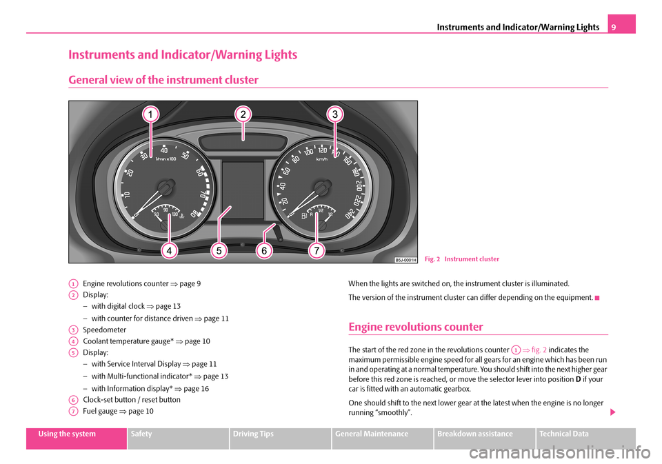
Engine revolutions counter ⇒page 9
Display:
− with digital clock ⇒page 13
− with counter for distance driven ⇒page 11
Speedometer
Coolant temperature gauge* ⇒page 10
Display:
− with Service Interval Display ⇒page 11
− with Multi-functional indicator* ⇒page 13
− with Information display* ⇒page 16
Clock-set button / reset button
Fuel gauge ⇒page 10
When the lights are switched on, the instrument cluster is illuminated.
The version of the instrument cluster can differ depending on the equipment.
Engine revolutions counter
The start of the red zone in the revolutions counter ⇒fig. 2 indicates the maximum permissible engine speed for all gears for an engine which has been run in and operating at a normal temperature. Yo u should shift into the next higher gear before this red zone is reached, or move the selector lever into position D if your car is fitted with an automatic gearbox.
One should shift to the next lower gear at the latest when the engine is no longer running “smoothly”.
Fig. 2 Instrument cluster
A1
A2
A3
A4
A5
A6
A7
A1
NKO A05F 20 MR08.book Page 9 Thursday, April 19, 2007 11:34 AM
Page 12 of 242
Instruments and Indicator/Warning Lights11
Using the systemSafetyDriving TipsGeneral MaintenanceBreakdown assistanceTechnical Data
Counter for distance driven
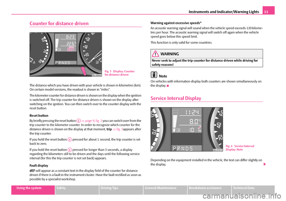
The distance which you have driven with your vehicle is shown in kilometres (km). On certain model versions, the readout is shown in “miles”.
The kilometer counter for distance driven is shown on the display when the ignition is switched off. The trip counter for dist ance driven is shown on the display after switching on the ignition. You can then swit ch over to the counter display with the reset button.
Reset button
By briefly pressing the reset button ⇒page 9, fig. 2 you can switch over from the trip counter to the kilometer counter. In order to recognize which counter for the distance driven is shown on the display at that moment, trip ⇒fig. 3appears after the trip counter.
If you hold the reset button pressed for about 1 second, the trip counter is set back to zero.
If you hold the reset button pressed for longer than 3 seconds, a display regarding the kilometers still to be driven and the days until the following service interval (for this the trip counter is not set back) appears.
Fa ult di spl a y
dEF will appear as a constant text in the display field of the counter for distance driven if there is a fault in the instrument cluster. Have the fault rectified as soon as possible by a specialist workshop.
Warning against excessive speeds*
An acoustic warning signal will sound when the vehicle speed exceeds 120 kilome- tres per hour. The acoustic warning signal will switch off again when the vehicle speed goes below this speed limit.
This function is only valid for some countries.
WARNING
Never seek to adjust the trip counter for distance driven while driving for safety reasons!
Note
On vehicles with information display bo th counters are shown simultaneously on the display.
Service Interval Display
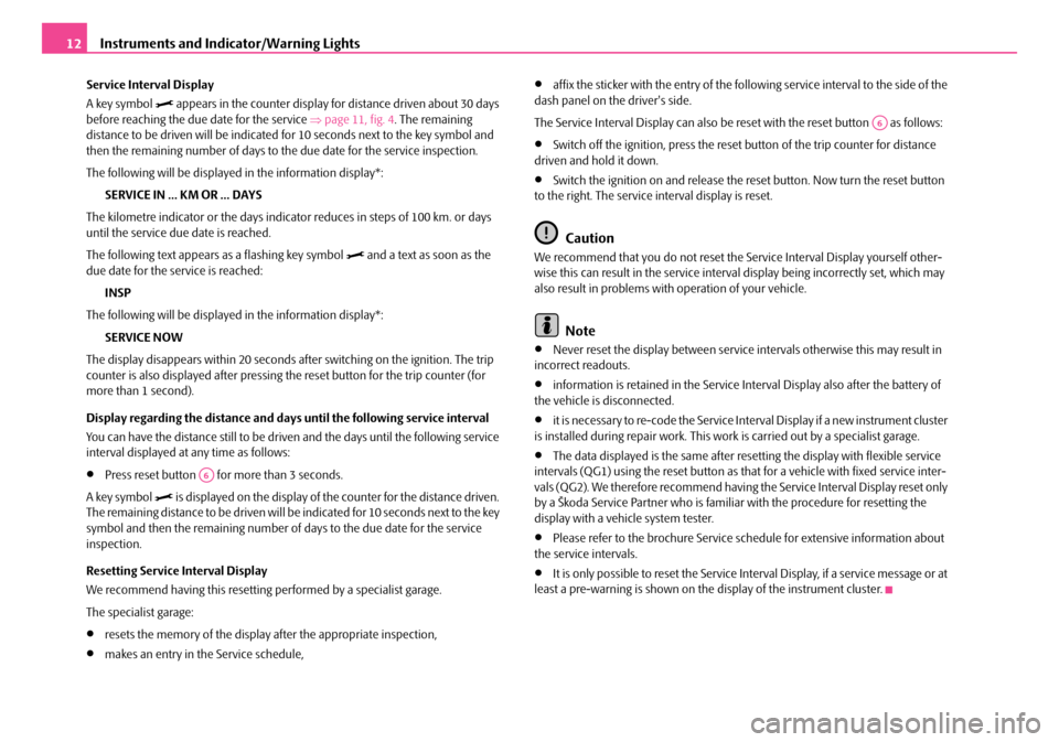
Depending on the equipment installed in the vehicle, the text can differ slightly on the display.
Fig. 3 Display: Counter for distance driven
A6
A6
A6Fig. 4 Service Interval Display: Note
NKO A05F 20 MR08.book Page 11 Thursday, April 19, 2007 11:34 AM
Page 13 of 242
Instruments and Indicator/Warning Lights12
Service Interval Display
A key symbol appears in the counter display for distance driven about 30 days before reaching the due date for the service ⇒page 11, fig. 4. The remaining distance to be driven will be indicated for 10 seconds next to the key symbol and then the remaining number of days to th e due date for the service inspection.
The following will be displayed in the information display*:
SERVICE IN ... KM OR ... DAYS
The kilometre indicator or the days indica tor reduces in steps of 100 km. or days until the service due date is reached.
The following text appears as a flashing key symbol and a text as soon as the due date for the service is reached:
INSP
The following will be displayed in the information display*:
SERVICE NOW
The display disappears within 20 seconds af ter switching on the ignition. The trip counter is also displayed after pressing th e reset button for the trip counter (for more than 1 second).
Display regarding the distance and days until the following service interval
You can have the distance still to be driv en and the days until the following service interval displayed at any time as follows:
•Press reset button for more than 3 seconds.
A key symbol is displayed on the display of the counter for the distance driven. The remaining distance to be driven will be indicated for 10 seconds next to the key symbol and then the remaining number of days to the due date for the service inspection.
Resetting Service Interval Display
We recommend having this resetting performed by a specialist garage.
The specialist garage:
•resets the memory of the display after the appropriate inspection,
•makes an entry in the Service schedule,
•affix the sticker with the entry of the following service interval to the side of the dash panel on the driver's side.
The Service Interval Display can also be reset with the reset button as follows:
•Switch off the ignition, press the reset button of the trip counter for distance driven and hold it down.
•Switch the ignition on and release the reset button. Now turn the reset button to the right. The service interval display is reset.
Caution
We recommend that you do not reset the Service Interval Display yourself other- wise this can result in the service interval display being incorrectly set, which may also result in problems with operation of your vehicle.
Note
•Never reset the display between service intervals otherwise this may result in incorrect readouts.
•information is retained in the Service Interval Display also after the battery of the vehicle is disconnected.
•it is necessary to re-code the Service Interval Display if a new instrument cluster is installed during repair work. This work is carried out by a specialist garage.
•The data displayed is the same after resetting the display with flexible service intervals (QG1) using the reset button as th at for a vehicle with fixed service inter- vals (QG2). We therefore recommend having the Service Interval Display reset only by a Škoda Service Partner who is famili ar with the procedure for resetting the display with a vehicle system tester.
•Please refer to the brochure Service schedule for extensive information about the service intervals.
•It is only possible to reset the Service Interval Display, if a service message or at least a pre-warning is shown on the display of the instrument cluster.
A6
A6
NKO A05F 20 MR08.book Page 12 Thursday, April 19, 2007 11:34 AM
Page 18 of 242
Instruments and Indicator/Warning Lights17
Using the systemSafetyDriving TipsGeneral MaintenanceBreakdown assistanceTechnical Data
Menu
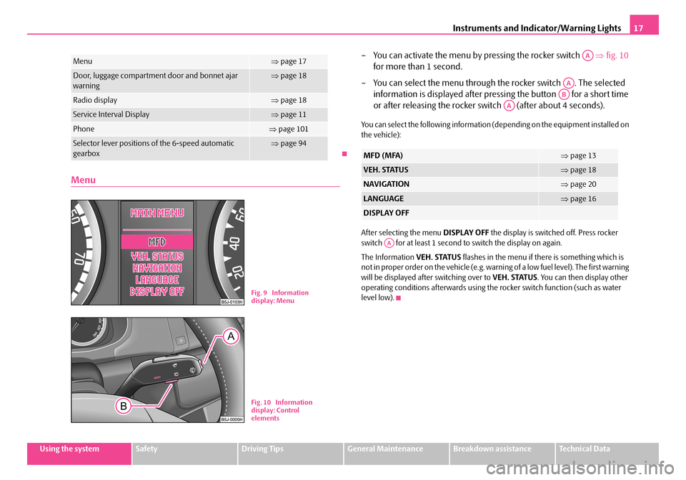
– You can activate the menu by pressing the rocker switch ⇒fig. 10
for more than 1 second.
– You can select the menu through the rocker switch . The selected
information is displayed after pressing the button for a short time
or after releasing the rocker sw itch (after about 4 seconds).
You can select the following information (depending on the equipment installed on the vehicle):
After selecting the menu DISPLAY OFF the display is switched off. Press rocker switch for at least 1 second to switch the display on again.
The Information VEH. STATUS flashes in the menu if there is something which is not in proper order on the vehicle (e.g. warning of a low fuel level). The first warning will be displayed after switching over to VEH. STATUS. You can then display other operating conditions afterwards using the rocker switch function (such as water level low).
Menu⇒ page 17
Door, luggage compartment door and bonnet ajar warning⇒ page 18
Radio display⇒page 18
Service Interval Display⇒page 11
Phone⇒page 101
Selector lever positions of the 6-speed automatic gearbox⇒ page 94
Fig. 9 Information display: Menu
Fig. 10 Information display: Control elements
MFD (MFA)⇒ page 13
VEH. STATUS⇒page 18
NAVIGATION⇒page 20
LANGUAGE⇒page 16
DISPLAY OFF
AA
AA
AB
AA
AA
NKO A05F 20 MR08.book Page 17 Thursday, April 19, 2007 11:34 AM
Page 19 of 242
Instruments and Indicator/Warning Lights18
Door, luggage compartment door and bonnet ajar warning
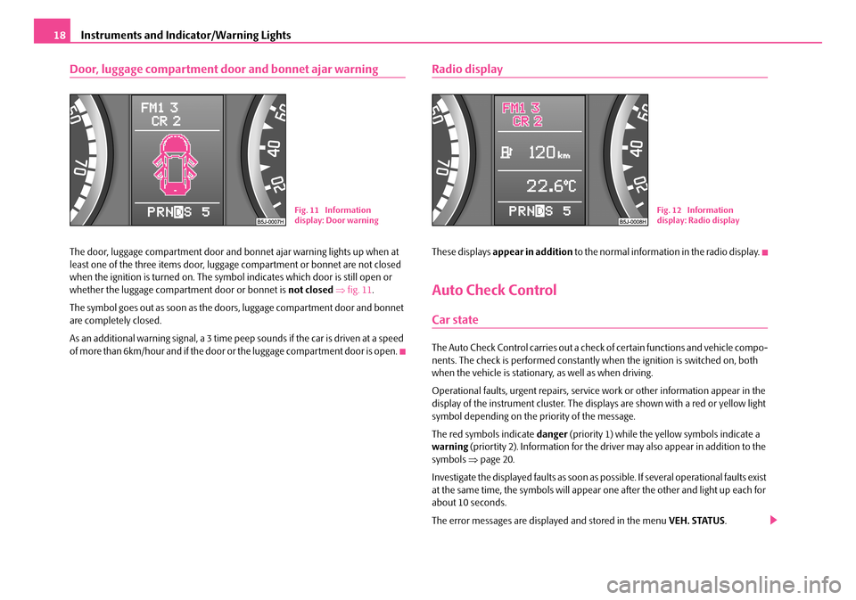
The door, luggage compartment door and bonnet ajar warning lights up when at least one of the three items door, luggage compartment or bonnet are not closed when the ignition is turned on. The symbol indicates which door is still open or whether the luggage compartment door or bonnet is not closed ⇒fig. 11.
The symbol goes out as soon as the doors, luggage compartment door and bonnet are completely closed.
As an additional warning signal, a 3 time peep sounds if the car is driven at a speed o f m o re t h a n 6 k m /h o u r a n d i f t h e d o o r o r t h e l u g g a g e c o m p a r tm e n t d o o r i s o p e n .
Radio display
These displays appear in addition to the normal information in the radio display.
Auto Check Control
Car state
The Auto Check Control carries out a check of certain functions and vehicle compo- nents. The check is performe d constantly when the ignition is switched on, both when the vehicle is stationary, as well as when driving.
Operational faults, urgent repairs, service work or other information appear in the display of the instrument cluster. The displays are shown with a red or yellow light symbol depending on the priority of the message.
The red symbols indicate danger (priority 1) while the yellow symbols indicate a warning (priortity 2). Information for the driver may also appear in addition to the symbols ⇒page 20.
Investigate the displayed faults as soon as possible. If several operational faults exist at the same time, the symbols will appear one after the other and light up each for about 10 seconds.
The error messages are displayed and stored in the menu VEH. STATUS.
Fig. 11 Information display: Door warningFig. 12 Information display: Radio display
NKO A05F 20 MR08.book Page 18 Thursday, April 19, 2007 11:34 AM
Page 29 of 242
Instruments and Indicator/Warning Lights28
Brake system
The warning light flashes or comes on if the brake fluid level is too low, if there is a fault in the ABS or if the handbrake is applied.
If the warning light flashes (handbrake is not applied), stop and check the brake fluid level ⇒.
The following text will be displayed in the information display*:
STOP BRAKE FLUID SERVICE MANUAL
If there is a fault in the ABS which also influences the function of the normal brake system (e.g. distribution of brake pressure), the ABS warning light comes on together with the brake system warning light . Be aware that not only the ABS but also another part of th brake system is defective ⇒.
3 peeps sound as an additional warning signal.
One should get used to high pedal forces, long braking distances and long free play of the brake pedal when driving to the next specialist garage.
The following text will be displayed in the information display*:
STOP BRAKE FAULT OWNER'S MANUAL!
For further information on the brake system ⇒page 146, “Brakes”.
Handbrake applied
The warning light also comes on if the handbrake is applied. An audible warning is also given if you drive the vehicle for at least 3 seconds at a speed of more than 6 km/h.
The following text will be displayed in the information display*:
HANDBRAKE ON
WARNING
•Pay attention to the following instructions ⇒page 173, “Working in the engine compartment” before checking the brake fluid level and opening the bonnet.
•If the brake system warning light does not go out a few seconds after switching on the ignition or comes on when driving, stop immediately and check the brake fluid in the reservoir ⇒page 180, “Brake fluid”. If the fluid level has dropped below the MIN marking, do not drive any further - risk of accident! Contact a Škoda dealer to obtain professional assistance.
Airbag system
Monitoring the airbag system
The warning light comes on for a few seconds when the ignition is switched on.
There is a fault in the system if the warning light does not go out or comes on or flashes while driving ⇒. This also applies if the warning light does not come on after the ignition is switched on.
The following text will be displayed in the information display*:
AIRBAG FAULT
The functionality of the airbag system is also monitored electronically, when one airbag has been switched off.
The passenger front airbag and also poss ibly the passenger side airbag which have been switched off using the vehicle system tester:
•The warning light lights up for 3 seconds after switching on the ignition and then flashes for 12 seconds afterwards in 2 second intervals.
The passenger front airbag and also poss ibly the passenger side airbag which have been switched off using the switch (for switching off airbags)* in the end face of the dash panel on the front passenger side:
•The warning light comes on for 3 seconds after the ignition has been switched on.
•Switching off airbags is indicated in the middle of the dash panel by the lighting up of the indicator light (airbag switched off) ⇒page 132.
WARNING (continued)
NKO A05F 20 MR08.book Page 28 Thursday, April 19, 2007 11:34 AM
Page 34 of 242
Unlocking and locking33
Using the systemSafetyDriving TipsGeneral MaintenanceBreakdown assistanceTechnical Data
Central locking system*
Description
Unlocking or locking the vehicle causes all doors to be unlocked or locked at the same time by the central locking system. The boot lid is unlocked when opening. It can be opened by pressing the ha nd grip above the licence plate.
Operation of the central locking system is possible:
•from the outside using the vehicle key ⇒page 34,
•using the buttons for the central locking system ⇒page 35,
•by using the remote control ⇒page 37.
Indicator light in the driver's door on vehicles without anti-theft alarm system
After the car is locked, the indicator light flashes after 2 seconds.
After the car is locked with the deactivate d safe securing system, the indicator light flashes only after 30 seconds.
Indicator light in the driver's door on vehicles with anti-theft alarm system
After locking the vehicle the indicator light flashes for 2 seconds fast, then more slowly.
If the vehicle is locked and the safe securing system ⇒page 34 is not operating, the indicator light in the driver door flashes for about 2 seconds fast, goes out and starts to flash slowly after about 30 seconds.
If the indicator light first of all flashes fast for about 2 seconds, afterwards lights up for about 30 seconds and then flashes slowly, there is a fault in the system of the central locking or the interior monitor* ⇒page 40. Contact a specialist garage to obtain assistance.
Convenience operation of windows
One can open and close the electrically powered windows when unlocking and locking the vehicle ⇒page 42, “Window convenience operation”.
Opening a single door*
This function allows one to just unlock the driver's door. The other doors remain locked and are only unlocked when the command is repeated. The single door opening function can be first activated by recoding the control unit of the central locking system. This work is undertaken by a Škoda Service Partner can give you more information.
Automatic locking*
All the doors and the boot lid are locked automatically once the car reaches a speed of about 15 km/h.
If the ignition key is withdrawn, the car is then automatically unlocked again. In addition, it is possible for the driver to unlock the car by pressing the central locking button or by pulling the door opening lever.
If you wish, your Škoda Service Partner ca n convert the central locking system of your car to the automatic locking mode.
WARNING
•Locking the doors prevents involuntar y opening in an exceptional situa- tion (an accident). Locked doors prevent unwanted entry into the vehicle from outside, for example at road crossings. Locked doors do, however, make it more difficult for rescuers to get into the vehicle in an emergency - danger to life!
Note
•In the event of an accident in which the airbags are deployed, the locked doors are automatically unlocked in order to enable rescuers to gain access to the vehicle.
•Only the front doors can be unlocked and locked using the key if the central locking system fails. You can op erate the rear door manually.
− Emergency locking of the door ⇒page 36.
NKO A05F 20 MR08.book Page 33 Thursday, April 19, 2007 11:34 AM
Page 125 of 242
Airbag system124
Airbag system
Description of the airbag system
General information on the airbag system
The front airbag system is complementary to the three-point seat belts and offers additional protection in the head and chest area of the driver and passenger in the event of a frontal collision.
In the event of a side collision, the side airbags reduce the risk of injury to the occu- pants to the part of their body facing the side of the accident.
The airbag system is only functional after the ignition has been switched on.
The operational readiness of the airbag system is monitored electronically. The airbag warning light comes on for a few seconds each time the ignition is switched on.
The airbag system (according to vehicl e equipment) essentially consists of:
•an electronic control unit,
•the front airbags for the driver and front passenger ⇒page 126,
•the side airbags ⇒page 128,
•head airbags ⇒page 130,
•an airbag warning light in the instrument cluster ⇒page 28,
•a front passenger airbag switch* ⇒page 132,
•an indicator light for a switched off front seat passenger airbag* in the middle of the dash panel ⇒page 132.
A fault in the airbag system exists if:
•the airbag indicator light does not light up when the ignition is switched on,
•the airbag indicator light does not go out after about 3 seconds after the ignition is switched on,
•the airbag indicator light goes out and comes on again after the ignition is switched on,
•the airbag indicator light comes on or flickers when driving,
•an airbag indicator light showing a swit ched-off front passenger airbag* in the middle of the dash panel flashes.
WARNING
•To enable the occupants of a car to be protected with the greatest possible effect when the airbag is deployed, the front seats must be ⇒ page 115, “Correct seated position” correctly adjusted to match the body size of the occupant.
•If you do not fasten the seat belts when driving, lean too far forward or adopt an incorrect seated position, you are exposing yourself to increased risk of injury in the event of an accident.
•Have the airbag system checked imme diately by a specialist garage if a fault exists. Otherwise, there is a risk of the airbag not being activated in the event of an accident.
•No modifications of any kind may be made to parts of the airbag system.
•It is prohibited to manipulate individual parts of the airbag system as this might result in the airbag being deployed.
•The protective function of the airbag system is sufficient for only one accident. The airbag system must then be replaced if the airbag has been deployed.
•The airbag system needs no maintenance during its working life.
•If you sell your car, please hand over the complete vehicle documenta-tion to the new owener. Please note that the documents relating to the possibility of deactivating the front passenger airbag are also part of the vehicle documents!
•If the vehicle or individual parts of the airbag system are scrapped, it is essential to observe the relevant safety precautions. Škoda Service Partners are familiar with these regulations.
•When disposing of vehicle or parts of the airbag system, it is important to comply with the national legal requirements.
NKO A05F 20 MR08.book Page 124 Thursday, April 19, 2007 11:34 AM
Page 133 of 242
Airbag system132
•special attachments are required in the area of the steering wheel because of a physical disability,
•you have installed other seats (e.g. orthopaedic seats without side airbags).
Monitoring the airbag system
The functionality of the airbag system is also monitored electronically, when one airbag has been switched off
If the airbag was switched off using diagnostic equipment:
•The airbag indicator light in the instrument cluster lights up for about 3 seconds after switching on the ignition and then flashes after that for about 12 seconds.
If the airbag was switched off using the airbag switch* on the side of the dash panel:
•The airbag warning light comes on in the instrument cluster for about 3 seconds each time the igniti on is switched on.
•Switching off airbags is indicated in the middle of the dash panel by the lighting up of the indicator light ⇒page 132, fig. 123.
Note
Your Škoda Service Partner will be able to advise you whether national legislation in your country allows airbags in your vehicle to be deactivated, and which ones.
Switch for the front seat passenger airbag(s)*
The front passenger front as well as side airbag (if the vehicle is fitted with
side airbags) are switched off using the switch.
Deactivating an airbag
– Switch off the ignition.
– Turn the slot of the airbag switch us ing the ignition key in the direction
of the arrow to the position OFF ⇒fig. 122.
– Check whether the airbag indicator light in the middle of the
dash panel lights up ⇒fig. 123 when the ignition is turned on.
Switching on an airbag
– Switch off the ignition.
– Turn the slot of the airbag switch us ing the ignition key in the direction
of the arrow to the position ON ⇒fig. 122.
– Check whether the airbag indicator light in the middle of the
dash panel lights up ⇒fig. 123 when the ignition is turned on.
The airbags should only be switched off under exceptional circumstances ⇒ page 131.Fig. 122 Switch for the front seat passenger airbag(s)
Fig. 123 Indicator light for a switched off front seat passenger airbag
NKO A05F 20 MR08.book Page 132 Thursday, April 19, 2007 11:34 AM