Heating control SKODA FABIA 2012 2.G / 5J User Guide
[x] Cancel search | Manufacturer: SKODA, Model Year: 2012, Model line: FABIA, Model: SKODA FABIA 2012 2.G / 5JPages: 196, PDF Size: 4.83 MB
Page 75 of 196
WARNING
Do not leave recirculated air mode on over a longer period of time, as “stale”
air can cause fatigue of the driver and passengers, reduce attention levels and
also cause the windows to mist up. The risk of having an accident increases.
Switch off recirculated air mode as soon as the windows start to mist up. ÐAir conditioning system (manual air conditioning
system) Introductory information
The cooling system only operates if the button AC 2
» Fig. 79 on page
73 is
pressed, and the following conditions are met:
› engine running;
› outside temperature above approx. +2 °C;
› blower switch switched on (positions 1 to 4).
Under certain circumstances, air at a temperature of about 5 °C can flow out of
the vents when the cooling system is switched on. Lengthy and uneven distribu-
tion of the air flow out of the vents and large differences in temperature, for ex-
ample when getting out of the vehicle, can result in chills in sensitive persons. Note
We recommend that you have the air conditioning system cleaned by a ŠKODA
specialist garage once every year. Ð Using the system
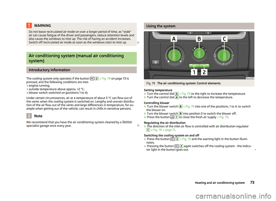
Fig. 79
The air conditioning system: Control elements
Setting temperature
› Turn the control dial A
» Fig. 79 to the right to increase the temperature.
› Turn the control dial A
to the left to decrease the temperature.
Controlling blower
› Turn the blower switch B
» Fig. 79
into one of the positions, 1 to 4, to switch
the blower on.
› Turn the blower switch B
into position 0 to switch the blower off.
› Press the button
1
to close the fresh air supply
» Fig. 79.
Regulating the air distribution
› The direction of the inlet air flow is controlled with air distribution regulator C
» Fig. 79 » page 71.
Switching the cooling system on and off
› Press the button
AC 2
» Fig. 79
and the warning light in the button illumi-
nates.
› Pressing the button
AC 2
again switches off the cooling system - the indica-
tor light in the button goes out. £
73
Heating and air conditioning system
Page 77 of 196
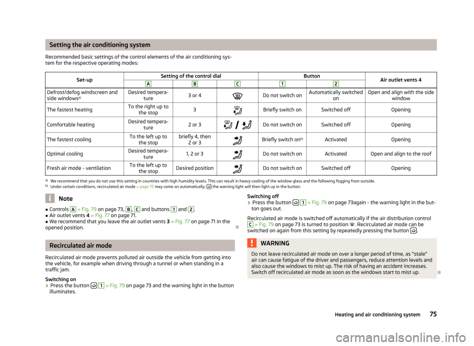
Setting the air conditioning system
Recommended basic settings of the control elements of the air conditioning sys-
tem for the respective operating modes:
Set-up Setting of the control dial
Button
Air outlet vents 4 A B C 1 2
Defrost/defog windscreen and
side windows
a) Desired tempera-
ture 3 or 4
Do not switch on Automatically switched
on Open and align with the side
window
The fastest heating To the right up to
the stop 3
Briefly switch on Switched off
Opening
Comfortable heating Desired tempera-
ture 2 or 3
Do not switch on Switched off
Opening
The fastest cooling To the left up to
the stop briefly 4, then
2 or 3 Briefly switch on
b)
Activated Opening
Optimal cooling Desired tempera-
ture 1, 2 or 3
Do not switch on Activated Open and align to the roof
Fresh air mode - ventilation To the left up to
the stop Desired position
Do not switch on Switched off
Openinga)
We recommend that you do not use this setting in countries with high humidity levels. This can result in heavy cooling of the window glass and the following fogging from outside.
b) Under certain conditions, recirculated air mode » page 75 may come on automatically; the warning light will then light up in the button.
Note
■ Controls A
» Fig. 79 on page 73
, B
, C
and buttons 1
and 2
.
■ Air outlet vents 4 » Fig. 77 on page 71 .
■ We recommend that you leave the air outlet vents 3 » Fig. 77 on page 71 in the
opened position. ÐRecirculated air mode
Recirculated air mode prevents polluted air outside the vehicle from getting into
the vehicle, for example when driving through a tunnel or when standing in a
traffic jam.
Switching on
› Press the button
1
» Fig. 79 on page 73
and the warning light in the button
illuminates. Switching off
› Press the button
1
» Fig. 79 on page 73
again - the warning light in the but-
ton goes out.
Recirculated air mode is switched off automatically if the air distribution control C
» Fig. 79 on page 73
is turned to position . Recirculated air mode can be
switched on again from this setting by repeatedly pressing the button .
WARNING
Do not leave recirculated air mode on over a longer period of time, as “stale”
air can cause fatigue of the driver and passengers, reduce attention levels and
also cause the windows to mist up. The risk of having an accident increases.
Switch off recirculated air mode as soon as the windows start to mist up. Ð
75
Heating and air conditioning system
Page 79 of 196
Recirculated air mode
Switch cooling system on/off
Note
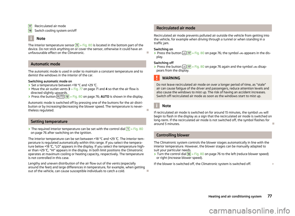
The interior temperature sensor 11
» Fig. 80
is located in the bottom part of the
device. Do not stick anything on or cover the sensor, otherwise it could have an
unfavourable effect on the Climatronic. ÐAutomatic mode
The automatic mode is used in order to maintain a constant temperature and to
demist the windows in the interior of the car.
Switching automatic mode on
› Set a temperature between +18 °C and +29
℃.
› Move the air outlet vents
3 » Fig. 77 on page 71 and 4 so that the air flow is
directed slightly upwards.
› Press the button
AUTO 12
» Fig. 80
on page
76; AUTO is shown in the display.
Automatic mode is switched off by pressing one of the buttons for the air distri-
bution or by increasing/decreasing the blower speed. The temperature is never-
theless regulated. ÐSetting temperature
› The required interior temperature can be set with the control dial 1
» Fig. 80
on page 76 after switching on the ignition.
The interior temperature can be set between +18 °C and +29 ℃. The interior tem-
perature is regulated automatically within this range. If you select the tempera-
ture below +18 ℃, “LO
” appears in the display. If you select the temperature high-
er than +29 ℃, “HI” appears in the display. In both limit positions the Climatronic
operates at maximum cooling or heating capacity, respectively. The temperature
is not controlled in this case.
Lengthy and uneven distribution of the air flow out of the vents (especially
around the feet) and large differences in temperature, for example, when getting
out of the vehicle, can cause susceptible individuals to catch a cold. Ð17
18 Recirculated air mode
Recirculated air mode prevents polluted air outside the vehicle from getting into
the vehicle, for example when driving through a tunnel or when standing in a
traffic jam.
Switching on
› Press the button
17
» Fig. 80
on page
76; the symbol appears in the dis-
play.
Switching off
› Press the button
17
» Fig. 80
on page
76 again and the symbol disap-
pears from the display. WARNING
Do not leave recirculated air mode on over a longer period of time, as “stale”
air can cause fatigue of the driver and passengers, reduce attention levels and
also cause the windows to mist up. The risk of having an accident increases.
Switch off recirculated air mode as soon as the windows start to mist up. Note
If recirculated air mode is switched on for around 15 minutes, the symbol will
begin to flash in the display as a sign that the recirculated air mode is switched on
long-term. If the recirculated air mode is not switched off, the symbol flashes for
around 5 minutes. Ð Controlling blower
The Climatronic system controls the blower stages automatically in line with the
interior temperature. However, the blower stages can be manually adapted to
suit your particular needs.
› Turn the control dial 10
» Fig. 80 on page 76 to the left (reduce blower speed)
or right (increase blower speed).
If the blower is switched off, the Climatronic system is switched off. £
77
Heating and air conditioning system
Page 83 of 196
Ignition lock
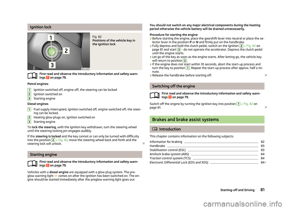
Fig. 82
Positions of the vehicle key in
the ignition lock
First read and observe the introductory information and safety warn-
ings on page 79.
Petrol engines
Ignition switched off, engine off, the steering can be locked
Ignition switched on
Starting engine
Diesel engines Fuel supply interrupted, ignition switched off, engine switched off, the steer-
ing can be locked.
Heating glow plugs on, ignition switched on
Starting engine
To lock the steering , with the ignition key withdrawn, turn the steering wheel
until the steering locking pin engages audibly.
If the steering is locked and the key cannot or can only be turned with difficulty
into the position 2
» Fig. 82, move the steering wheel back and forth and the
steering lock will unlock. ÐStarting engine
First read and observe the introductory information and safety warn-
ings on page 79.
Vehicles with a diesel engine are equipped with a glow plug system. The pre-
glow warning light comes on after the ignition has been switched on. The en-
gine should be started immediately after the preglow warning light goes out.
ä 1
2
3
1
2
3
ä You should not switch on any major electrical components during the heating
period otherwise the vehicle battery will be drained unnecessarily.
Procedure for starting the engine
› Before starting the engine, place the gearshift lever into neutral or place the se-
lector lever in the position P or N and firmly put on the handbrake.
› Fully depress and hold the clutch pedal, switch on the ignition 2
» Fig. 82 on
page 81 and start 3
- do not operate the accelerator. Depress the clutch pedal
until the engine starts.
› Let go of the key as soon as the engine starts. After letting go, the vehicle key
will return to position 2
.
› If the engine does not start within 10
seconds, abort the start-up process and
turn the key to position 1
. Repeat the start-up process after approx. half a mi-
nute.
› Release the handbrake before starting off. Ð Switching off the engine
First read and observe the introductory information and safety warn-
ings on page 79.
Switch off the engine by turning the ignition key into position 1
» Fig. 82
on
page 81. Ð Brakes and brake assist systems
ä
Introduction
This chapter contains information on the following subjects:
Information for braking 82
Handbrake 83
Stabilisation control (ESC) 83
Antilock brake system (ABS) 84
Traction control system (TCS) 84
Electronic Differential Lock (EDS and XDS) 84
£
ä
81
Starting-off and Driving
Page 84 of 196
WARNING
■ The brake booster only operates when the engine is running. Greater physi-
cal effort for braking is required when the engine is switched off - risk of acci-
dent!
■ Depress the clutch pedal when stopping or braking a vehicle with a petrol
engine and manual transmission in the low rev range. If you fail to do so, the
functionality of the brake booster can be impaired - risk of accident!
■ If a front spoiler, full wheel trim, etc. is mounted retrospectively, it must be
ensured that the air supply to the front wheel brakes is not reduced. Other-
wise, the functionality of the brake system could be impaired - risk of acci-
dent! ■ Please note that the handbrake must be fully released. A handbrake which
is only partially released can result in the rear brakes overheating, which can
have a negative effect on the operation of the brake system - risk of accident!
■ Never leave children unattended in the vehicle. The children might, for ex-
ample, release the handbrake or take the vehicle out of gear. The vehicle
might then move off - risk of accident!
■ A lack of fuel can cause irregular engine running or cause the engine to shut
down. The brake assist systems would then be without function - risk of acci-
dent! ■ Adjust the speed and driving style to the current visibility, weather, road and
traffic conditions. The increased safety offered by the brake assist systems
must not tempt you to take greater risks than otherwise - risk of an accident!
■ The normal braking system is still fully functional if there is an ABS fault.
Visit a ŠKODA specialist garage immediately and adjust your style of driving
according to the damage to the ABS as you will not know how great the dam-
age is and the limitation it is placing on the braking efficiency. CAUTION
■ Observe the recommendations on the new brake pads » page 121.
■ Never let the brakes slip with light pressure on the pedal if braking is not neces-
sary. This causes the brakes to overheat and can also result in a longer braking
distance and excessive wear. ■ All four wheels must be fitted with the same tyres approved by the manufactur-
er to ensure the brake assist systems operate correctly. Note
■ If the brakes are applied in full and the control unit for the braking system con-
siders the situation to be dangerous for the following traffic, the brake light
flashes automatically. After the speed was reduced below around 10
km/h or the
vehicle was stopped, the brake light stops flashing and the hazard warning light
system switches on. The hazard warning light system is switched off automatical-
ly after accelerating or driving off again. ■ Before negotiating a steep downhill section, reduce the speed, shift down into
the next lower gear (manual gearbox) or select a lower drive position (automatic
gearbox). As a result, the braking effect of the engine will be used, reducing the
load on the brakes. Any additional braking should be completed intermittently,
not continuously. ■ Changes to the vehicle (e.g. to the engine, brakes, chassis or another combina-
tion of tyres and wheels) can influence the functionality of the brake assist sys-
tems »
page 157, Accessories, changes and replacement of parts .
■ If a fault occurs in the ABS system, the ESC, ASR and EDL and XDS also do not
work. A warning light » page 21 comes on if a fault occurs in the ABS system. Ð Information for braking
First read and observe the introductory information and safety warn-
ings on page 81.
Wear-and-tear
The wear of the brake pads is dependent on the operating conditions and driving
style. The brake pads wear more quickly if a lot of journeys are completed in
towns and over short distances or if a very sporty style of driving is adopted. If
operated under severe conditions, the thickness of the brake pads must be
checked by a ŠKODA specialist garage before the next service appointment.
Wet roads or road salt
The performance of the brakes can be delayed as the brake discs and brake pads
may be moist or have a coating of ice or layer of salt on them in winter. The
brakes are cleaned and dried by applying the brakes several times.
Corrosion
Corrosion on the brake discs and dirt on the bake pads occur if the vehicle has
been parked for a long period and if you do not make much use of the braking
system. If the brake system is not used much or if there is corrosion on the sur-
face, we recommend cleaning the brake discs by firmly applying the brakes from a
fairly high speed. £
ä
82 Using the system
Page 171 of 196
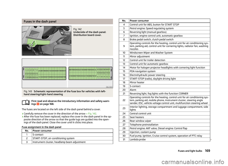
Fuses in the dash panel
Fig. 142
Underside of the dash panel:
Distribution board cover. Fig. 143
Schematic representation of the fuse box for vehicles with left-
hand steering/right-hand steering
First read and observe the introductory information and safety warn-
ings on page 168.
The fuses are located on the left side of the dash panel behind a cover.
›
Carefully remove the cover in the direction of the arrow
» Fig. 142.
› After the fuse has been replaced, replace the cover in the dash panel in the op-
posite direction of the arrow so that the guide lugs are guided into the open-
ings of the dash panel. Close the cover until it clicks into place.
Fuse assignment in the dash panel No. Power consumer
1 S-contact
2 START-STOP, air-conditioning system
3 Instrument cluster, headlamp beam adjustment ä No. Power consumer
4 Control unit for ABS, button for START STOP5 Petrol engine: Speed regulating system
6 Reversing light (manual gearbox) 7 Ignition, engine control unit, automatic gearbox
8 Brake pedal switch, clutch pedal switch
9 Operating controls for the heating, control unit for air conditioning sys-
tem, parking aid, control unit for cornering lights, radiator fan, washing
nozzles
10 Windscreen Wiper and Washer System 11 Mirror adjustment
12 Control unit for trailer detection
13 Control unit for automatic gearbox
14 Motor for halogen projector headlights with cornering light function 15 PDA navigation system
16 Electrohydraulic power steering 17 START-STOP (radio), daylight driving light
18 Mirror heater 19 S-contact
20 Alarm 21 Reversing light, fog lights with the function CORNER
22 Operating controls for the heating, control unit for air conditioning sys-
tem, parking aid, mobile phone, instrument cluster, steering angle
sender, ESC, vehicle voltage control unit, multifunction steering wheel
23 Interior lighting, storage compartment and luggage compartment, side
lights
24 Central control unit 25 Seat heaters
26 Rear window wiper 27 Telephone preinstallation
28 Petrol engine: AKF valve, Diesel engine: Control flap 29 Injection, coolant pump
30 Fuel pump, ignition, Cruise control system, operation of PTC relay 31 Lambda probe £ 169
Fuses and light bulbs
Page 172 of 196
No. Power consumer
32 High pressure fuel pump, pressure valve
33 Engine control unit
34 Engine control unit, vacuum pump 35 Power supply of ignition lock
36 Main beam 37 Rear fog light, DC/DC converter START-STOP
38 Fog lights 39 Air blower for heating
40-41 Not assigned 42 Rear window heater
43 Horn
44 Windscreen wipers 45 Central control unit for convenience system
46 Engine control unit, fuel pump 47 Cigarette lighter, power socket in the luggage compartment
48 ABS, START-STOP (DC/DC) converter ESP 49 Turn signal lights, brake lights50 START-STOP (DC/DC) converter infotainment, radio 51 Electrical power window (front and rear) - left side
52 Electrical power window (front and rear) - right side
53 Parking light = left side, electrical sliding/tilting roof
54 START-STOP (instrument cluster), alarm 55 Control unit for automatic gearbox
56 Headlight cleaning system, parking light - right side 57 Left low beam, headlight range adjustment
58 Low beam on the right Ð Fuses in the engine compartment
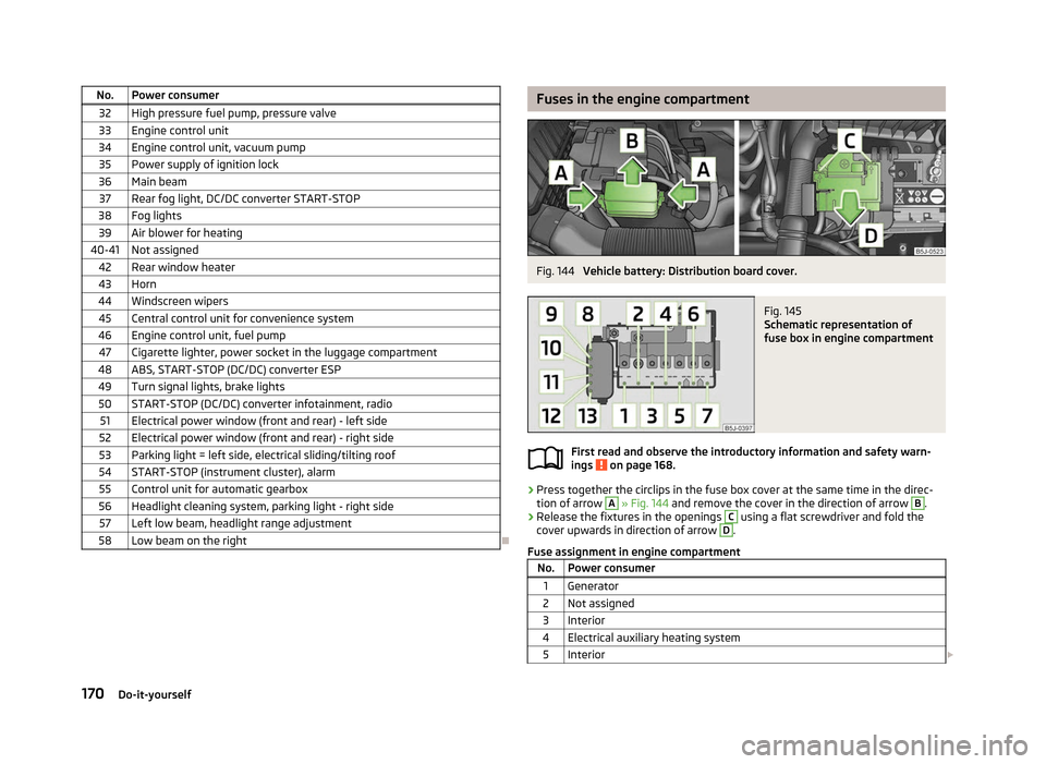
Fig. 144
Vehicle battery: Distribution board cover. Fig. 145
Schematic representation of
fuse box in engine compartment
First read and observe the introductory information and safety warn-
ings on page 168.
›
Press together the circlips in the fuse box cover at the same time in the direc-
tion of arrow A
» Fig. 144
and remove the cover in the direction of arrow B
.
› Release the fixtures in the openings C
using a flat screwdriver and fold the
cover upwards in direction of arrow D
.
Fuse assignment in engine compartment No. Power consumer
1 Generator
2 Not assigned
3 Interior
4 Electrical auxiliary heating system 5 Interior £ ä
170 Do-it-yourself
Page 173 of 196
No. Power consumer
6 Glow plugs, radiator fan7 Electrohydraulic power steering
8 ABS or TCS or ESC 9 Radiator fan
10 Automatic gearbox 11 ABS or TCS or ESC
12 Central control unit
13 Electrical auxiliary heating system Note
Fuses 1 - 7 are replaced by a specialist ŠKODA garage. ÐBulbs
ä
Introduction
This chapter contains information on the following subjects:
Headlights 172
Replacing a bulb for low beam and main beam (halogen headlights) 172
Replacing a bulb for low beam and main beam Halogen projector
headlights) 173
Replacing the bulb for the main beam (Halogen projector headlights) 173
Changing the bulb for the front turn signal light 173
Changing the light bulb for the front parking light 173
Fog lights and daytime running lights 174
Fog lights Fabia Scout, Fabia RS 174
Licence plate light 175
Tail lamp assembly 175
Some manual skills are required to change a bulb. For this reason, if uncertain, we
recommend that bulbs are replaced by a ŠKODA specialist garage or other expert
help is sought. ›
Switch off the ignition and all of the lights before replacing a bulb.
› Faulty bulbs must only be replaced with the same type of bulbs. The designa-
tion is located on the light socket or the glass bulb.
› A stowage compartment for replacement bulbs is located in a plastic box in the
spare wheel or underneath the floor covering in the boot. WARNING
■ Accidents can be caused if the road in front of the vehicle is not sufficiently
illuminated and the vehicle cannot or can only be seen with difficulty by other
road users.
■ Always read and observe the warnings before completing any work in the
engine compartment » page 138, Engine compartment .
■ Bulbs H7 and H4 are pressurised and may burst when changing the bulb -
risk of injury! We therefore recommended wearing gloves and safety glasses
when changing a bulb. CAUTION
■ Do not take hold of the glass bulb with naked fingers (even the smallest
amount of dirt reduces the working life of the light bulb). Use a clean cloth, nap-
kin, or similar. ■ When removing and installing the tail light make sure that the paintwork of the
vehicle and the tail light are not damaged. Note
■ This Owner's Manual only describes the replacement of bulbs where it is possi-
ble to replace the bulbs on your own without any complications arising. Other
light bulbs should be changed by a
ŠKODA specialist garage.
■ We recommend that a box of replacement bulbs be always carried in the vehi-
cle. Replacement bulbs can be purchased from
ŠKODAOriginal Accessories.
■ We recommend that the headlight settings are checked by a ŠKODA specialist
garage after replacing a bulb in the main or low beam.
■ LED diodes should be changed by a specialist ŠKODA garage. Ð
171
Fuses and light bulbs
Page 190 of 196
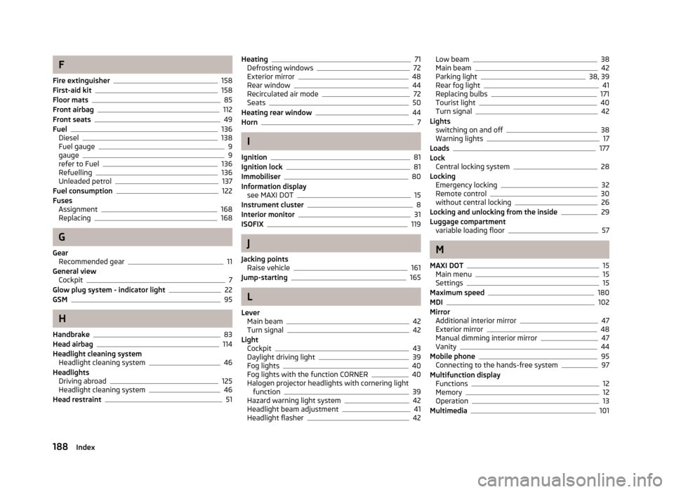
F
Fire extinguisher 158
First-aid kit 158
Floor mats 85
Front airbag 112
Front seats 49
Fuel 136
Diesel 138
Fuel gauge 9
gauge 9
refer to Fuel 136
Refuelling 136
Unleaded petrol 137
Fuel consumption 122
Fuses Assignment 168
Replacing 168
G
Gear Recommended gear 11
General view Cockpit 7
Glow plug system - indicator light 22
GSM 95
H
Handbrake 83
Head airbag 114
Headlight cleaning system Headlight cleaning system 46
Headlights Driving abroad 125
Headlight cleaning system 46
Head restraint 51Heating 71
Defrosting windows 72
Exterior mirror 48
Rear window 44
Recirculated air mode 72
Seats 50
Heating rear window 44
Horn 7
I
Ignition 81
Ignition lock 81
Immobiliser 80
Information display see MAXI DOT 15
Instrument cluster 8
Interior monitor 31
ISOFIX 119
J
Jacking points Raise vehicle 161
Jump-starting 165
L
Lever Main beam 42
Turn signal 42
Light Cockpit 43
Daylight driving light 39
Fog lights 40
Fog lights with the function CORNER 40
Halogen projector headlights with cornering light function 39
Hazard warning light system 42
Headlight beam adjustment 41
Headlight flasher 42Low beam 38
Main beam 42
Parking light 38, 39
Rear fog light 41
Replacing bulbs 171
Tourist light 40
Turn signal 42
Lights switching on and off 38
Warning lights 17
Loads 177
Lock Central locking system 28
Locking Emergency locking 32
Remote control 30
without central locking 26
Locking and unlocking from the inside 29
Luggage compartment variable loading floor 57
M
MAXI DOT 15
Main menu 15
Settings 15
Maximum speed 180
MDI 102
Mirror Additional interior mirror 47
Exterior mirror 48
Manual dimming interior mirror 47
Vanity 44
Mobile phone 95
Connecting to the hands-free system 97
Multifunction display Functions 12
Memory 12
Operation 13
Multimedia 101
188 Index
Page 191 of 196
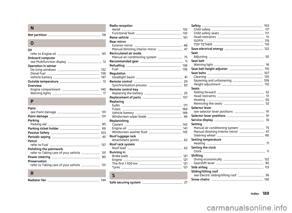
N
Net partition 58
O
Oil refer to Engine oil 141
Onboard computer see Multifunction display 12
Operation in winter De-icing windows 132
Diesel fuel 138
Vehicle battery 147
Outside temperature 13
Overview Engine compartment 140
Warning lights 17
P
Paint see Paint damage 131
Paint damage 131
Parking Parking aid 85
Parking ticket holder 69
Passive Safety 103
Periodic wiping 45
Petrol refer to Fuel 137
Polishing the paintwork refer to Taking care of your vehicle 131
Power steering 80
Preservation refer to Taking care of your vehicle 131
R
Radiator fan 144Radio reception
Aerial 132
Functional fault 132
Raise vehicle 161
Rear mirror Exterior mirror 48
Manual dimming interior mirror 47
Recirculated air mode Manual air conditioning system 75
Recommended gear 11
Refuelling 136
Fuel 136
Regulation Headlight beam 41
Remote control 29
Synchronisation process 30
Remote control key Replacing the battery 25
Replacement of parts 157
Replacing bulbs 171
Fuses 168
Vehicle battery 148
Windscreen wiper blade 46
Replenishing Coolant 143
Engine oil 141
Windscreen washer fluid 145
Roof luggage rack Attachment points 63
Roof rack system Roof load 63
Running in Brake pads 121
Engine 121
The first 1 500 km 121
Tyres 121
S
Safe securing system 27Safety 103
Child safety 117
Child safety seats 117
Head restraints 51
ISOFIX 119
TOP TETHER 119
Save electrical energy 122
Seat Adjusting 50
Seat belt Warning light 18
Seat belt height adjuster 110
Seat belts 107
Cleaning 135
fastening and unfastening 109
Height adjustment 110
Seats folding forward 52
Head restraints 51
Heating 50
Removing the seats 52
Selector lever see selector lever positions 91
Selector lever positions 91
Service display 10
Setting Manual air conditioning system 75
Manual dimming interior mirror 47
Steering wheel 80
Setting temperature Heating 71
Setting the clock Clock 11
Shifting Diving economically 122
Gearshift lever 85
Side airbag 113
Sliding/tilting roof see Electric sliding/tilting roof 36
Snow chains 156
189
Index