Light switch SKODA FABIA 2012 2.G / 5J Owner's Guide
[x] Cancel search | Manufacturer: SKODA, Model Year: 2012, Model line: FABIA, Model: SKODA FABIA 2012 2.G / 5JPages: 196, PDF Size: 4.83 MB
Page 43 of 196
The fog lights with the function CORNER are adjusted according to the steering
angle or after switching on the turn signal light
1)
in the following circumstances:
› the vehicle is stationary and the engine is running or it moves with a speed of
maximum 40 km/h;
› the daytime running lights are not switched on;
› the low beam is switched on;
› the fog lights are not switched on;
› no reverse gear is engaged. ÐRear fog light
First read and observe the introductory information and safety warn-
ings on page 38.
Switching on
› First of all, turn the light switch
» Fig. 23 on page 40 to position or .
› Pull the light switch to position 2
.
If the vehicle is not fitted with fog lights » page 40, the rear fog light is switched
on by turning the light switch to the position or and is pulled out directly to
the position 2
. This switch does not have two positions, but only one position.
The warning light
lights up in the instrument cluster when the rear fog light is
switched on » page 17.
Only the rear fog light on the trailer lights up if the vehicle has a factory-fitted
towing device or a towing device from ŠKODA original accessories and it is driven
with a trailer and the rear fog light switched on. Ð
ä Headlight beam adjustment
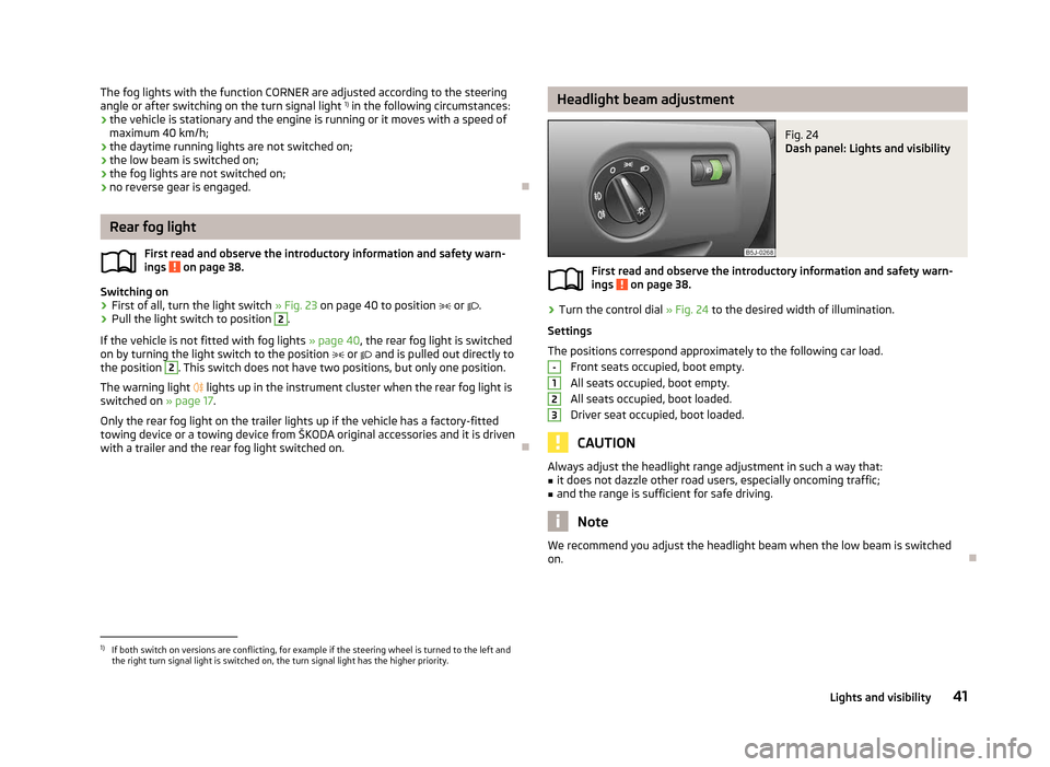
Fig. 24
Dash panel: Lights and visibility
First read and observe the introductory information and safety warn-
ings on page 38.
›
Turn the control dial
» Fig. 24 to the desired width of illumination.
Settings
The positions correspond approximately to the following car load. Front seats occupied, boot empty.
All seats occupied, boot empty.
All seats occupied, boot loaded.
Driver seat occupied, boot loaded. CAUTION
Always adjust the headlight range adjustment in such a way that:
■ it does not dazzle other road users, especially oncoming traffic;
■ and the range is sufficient for safe driving. Note
We recommend you adjust the headlight beam when the low beam is switched
on. Ð
ä -
1
2
3
1)
If both switch on versions are conflicting, for example if the steering wheel is turned to the left and
the right turn signal light is switched on, the turn signal light has the higher priority.
41
Lights and visibility
Page 44 of 196
Switches for the hazard warning light system
Fig. 25
Dash panel: Switch for hazard
warning lights
First read and observe the introductory information and safety warn-
ings on page 38.
›
Press switch
» Fig. 25 to switch the hazard warning light system on or off.
All the turn signal lights on the vehicle flash at the same time when the hazard
warning light system is switched on. The warning light for the turn signals and
the warning light in the switch also flash at the same time. The hazard warning
light system can also be operated if the ignition is switched off.
The hazard warning light system is switched on automatically if an airbag is de-
ployed in the event of an accident. Note
The hazard warning light system must be switched on if, for example:
■ you encounter a traffic congestion;
■ your vehicle breaks down or an emergency situation occurs. Ð
ä Turn signal and main beam lever
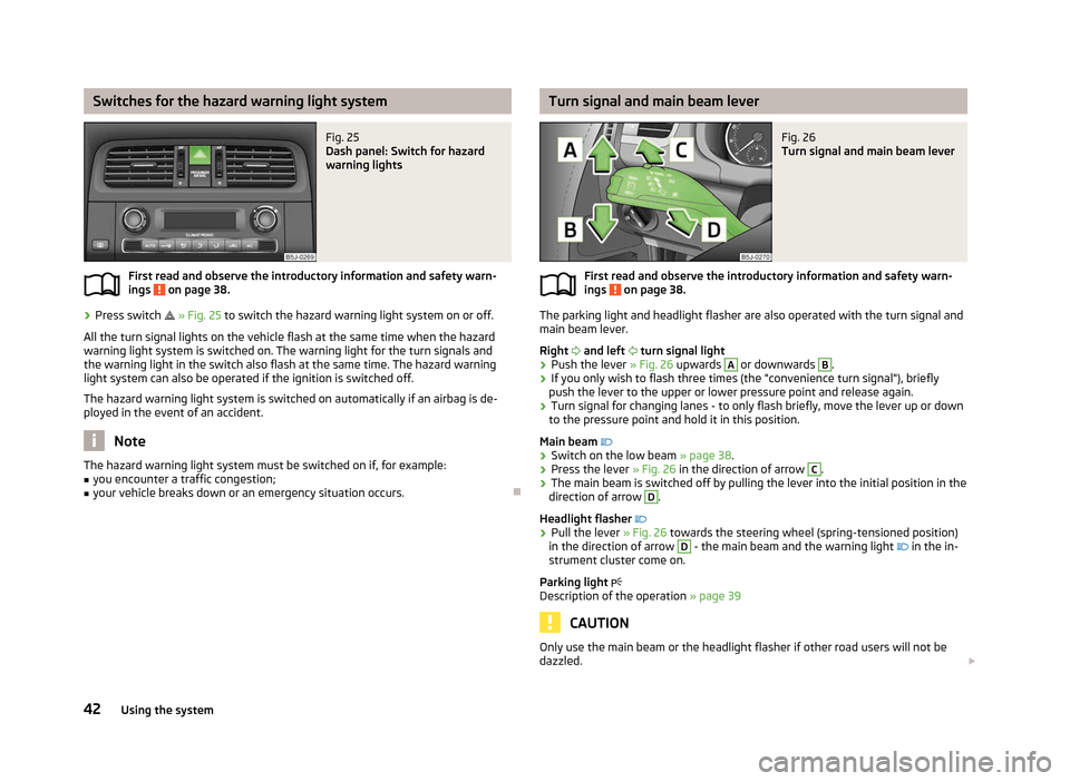
Fig. 26
Turn signal and main beam lever
First read and observe the introductory information and safety warn-
ings on page 38.
The parking light and headlight flasher are also operated with the turn signal and
main beam lever.
Right and left turn signal light
› Push the lever
» Fig. 26 upwards A
or downwards B
.
› If you only wish to flash three times (the "convenience turn signal"), briefly
push the lever to the upper or lower pressure point and release again.
› Turn signal for changing lanes - to only flash briefly, move the lever up or down
to the pressure point and hold it in this position.
Main beam
› Switch on the low beam » page 38.
› Press the lever
» Fig. 26 in the direction of arrow C
.
› The main beam is switched off by pulling the lever into the initial position in the
direction of arrow D
.
Headlight flasher
› Pull the lever
» Fig. 26 towards the steering wheel (spring-tensioned position)
in the direction of arrow D
- the main beam and the warning light
in the in-
strument cluster come on.
Parking light
Description of the operation » page 39 CAUTION
Only use the main beam or the headlight flasher if other road users will not be
dazzled. £
ä
42 Using the system
Page 45 of 196
Note
■ The turn signal system only operates when the ignition is switched on. The cor-
responding warning light or in the instrument cluster also flashes.
■ The turn signal is automatically cancelled after negotiating a curve.
■ The warning light flashes at twice its normal rate if a bulb for the turn signal
light fails. ÐInterior light
Interior lights at the front
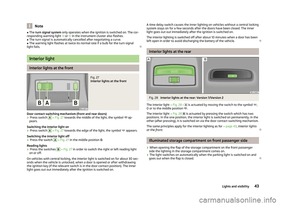
Fig. 27
Interior lights at the front
Door contact switching mechanism (front and rear doors) › Press switch A
» Fig. 27 towards the middle of the light, the symbol
ap-
pears.
Switching the interior light on
› Press switch A
» Fig. 27 towards the edge of the light, the symbol
appears.
Switching the interior light off
› Press the switch A
» Fig. 27 in the middle position
O.
Reading lights
› Press the switches B
» Fig. 27 in order to switch the right or left reading light
on or off.
On vehicles with central locking, the interior light is switched on for about 30 sec-
onds when the vehicle is unlocked, when a door is opened or after withdrawing
the ignition key (if the relevant switch is in the door contact position). The inner
light goes out out immediately after the ignition is switched on. A time delay switch causes the inner lighting on vehicles without a central locking
system stays on for a few seconds after the doors have been closed. The inner
light goes out out immediately after the ignition is switched on.
The interior lighting is switched off after about 10 minutes when a door has been
left open in order to avoid discharging the battery of the vehicle. Ð Interior lights at the rear
Fig. 28
Interior lights at the rear: Version 1/Version 2
The interior light » Fig. 28 -
is actuated by moving the switch to the symbol ,
O or to the middle position .
The interior light » Fig. 28 is actuated by pressing the switch which has two
positions. In the one position, the interior light is switched on permanently; in the
other (after pressing), it is switched on via the door contact switching mechanism.
The same principles apply for the interior lighting as for » page 43, Interior lights
at the front . Ð Illuminated storage compartment on front passenger side
› When opening the flap of the storage compartment on the front passenger
side the lighting in the storage compartment comes on.
› The light switches on automatically when the parking light is switched on and
goes out when the flap is closed. Ð
43
Lights and visibility
Page 46 of 196
Boot light
The light comes on automatically when the boot lid is opened. If the lid remains
open for more than about 10
minutes, the boot light switches off automatically. ÐVisibility
Rear window heater
Fig. 29
Switch for rear window heater
› The rear window heater is switched on or off by pressing the switch
»
Fig. 29
the warning light in the switch comes on or goes out.
The rear window heater only operates when the engine is running.
The rear window heater switches off automatically after 7 minutes. For the sake of the environment
The heating should be switched off as soon as the window is de-iced or free from
mist. The reduced current consumption will have a favourable effect on fuel econ-
omy »
page 124 , Saving electricity .Note
If the on-board voltage drops, the rear window heater switches off automatically,
in order to provide sufficient electrical energy for the engine control »
page 149,
Automatic load deactivation . Ð Sun visors
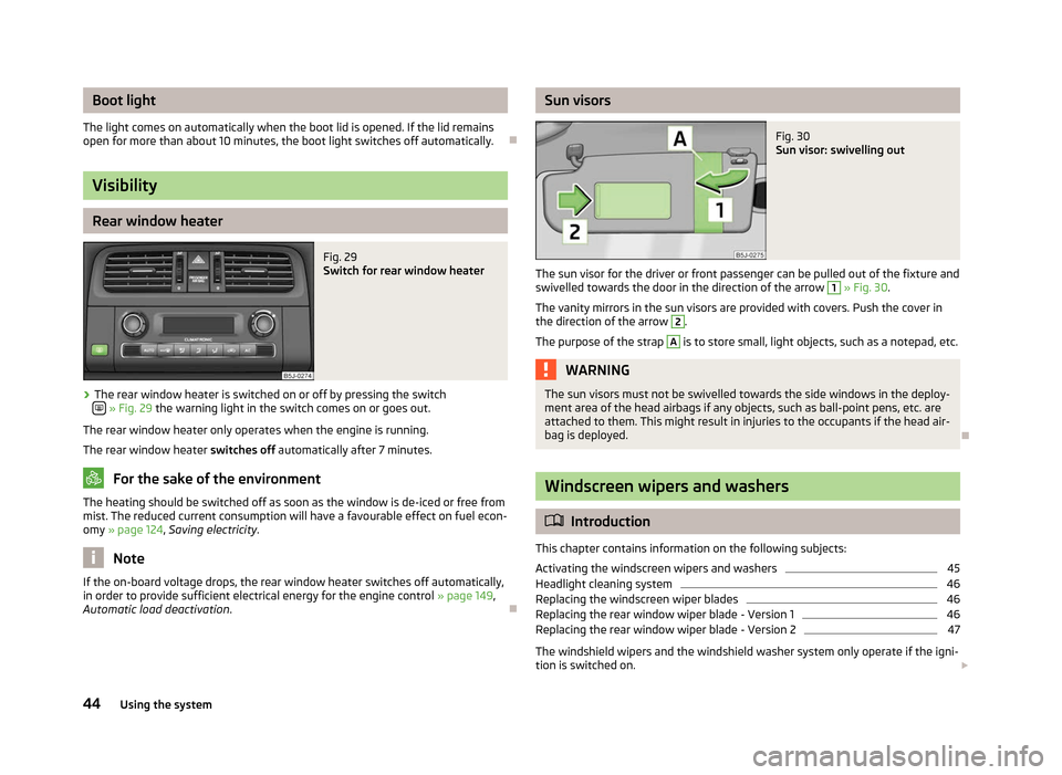
Fig. 30
Sun visor: swivelling out
The sun visor for the driver or front passenger can be pulled out of the fixture and
swivelled towards the door in the direction of the arrow 1
» Fig. 30.
The vanity mirrors in the sun visors are provided with covers. Push the cover in
the direction of the arrow 2
.
The purpose of the strap A
is to store small, light objects, such as a notepad, etc.
WARNING
The sun visors must not be swivelled towards the side windows in the deploy-
ment area of the head airbags if any objects, such as ball-point pens, etc. are
attached to them. This might result in injuries to the occupants if the head air-
bag is deployed. Ð Windscreen wipers and washers
ä
Introduction
This chapter contains information on the following subjects:
Activating the windscreen wipers and washers 45
Headlight cleaning system 46
Replacing the windscreen wiper blades 46
Replacing the rear window wiper blade - Version 1 46
Replacing the rear window wiper blade - Version 2 47
The windshield wipers and the windshield washer system only operate if the igni-
tion is switched on. £
44 Using the system
Page 47 of 196
The rear window is wiped once if the windscreen wipers are on when reverse
gear is selected.
Top up with windscreen wiper fluid
» page 145.WARNING
■ Properly maintained windscreen wiper blades are essential for clear visibility
and safe driving » page 46. ■ Do not use the windscreen washer system at low temperatures, without
heating the windscreen beforehand. Otherwise the window cleaner could
freeze on the windscreen and restrict the view to the front. CAUTION
■ In cold temperatures and during the winter, check before the journey or before
switching on the ignition that the wiper blades are not frozen to the windscreen.
If the windscreen wipers are switched on when the blades are frozen to the
windscreen, this may damage both the blades and windscreen wiper motor!
■ If the ignition is switched off while the windscreen wipers are switched on, the
windscreen wipers will continue wiping in the same mode after the ignition is
turned back on. The windscreen wipers could freeze up in cold temperatures be-
tween the time the ignition was turned off and when it was turned back on again.
■ Carefully detach frozen wiper blades from the front or rear window.
■ Remove snow and ice from the windscreen wipers before driving.
■ If the windscreen wipers are handled carelessly, there is a risk of damage to the
windscreen.
■ Replace the windscreen wiper blades once or twice a year for safety reasons.
These can be purchased from a ŠKODA Service Partner.Note
■ The windscreen washer nozzles for the windscreen are heated when the en-
gine is running and the outside temperature is less than approx. +10
°C.
■ The content of the windscreen washer fluid reservoir is 3.5 litres. On vehicles
fitted with the headlight cleaning system, the volume is around 5.4
litres.
■ The wiper blades should be cleaned on a regular basis with a windscreen clean-
er to avoid any smears. The wiper blades should be cleaned with a sponge or
cloth if they are heavily soiled by insect residues, for example. Ð Activating the windscreen wipers and washers
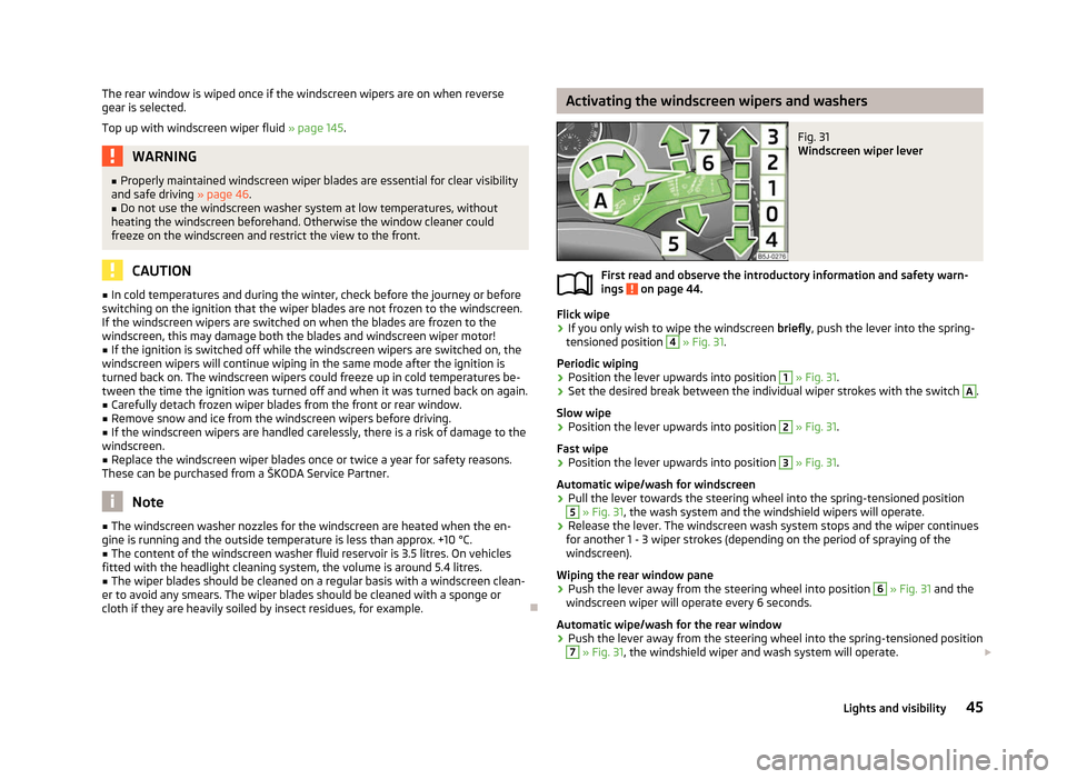
Fig. 31
Windscreen wiper lever
First read and observe the introductory information and safety warn-
ings on page 44.
Flick wipe
›
If you only wish to wipe the windscreen
briefly, push the lever into the spring-
tensioned position 4
» Fig. 31.
Periodic wiping
› Position the lever upwards into position 1
» Fig. 31.
› Set the desired break between the individual wiper strokes with the switch A
.
Slow wipe
› Position the lever upwards into position 2
» Fig. 31.
Fast wipe
› Position the lever upwards into position 3
» Fig. 31.
Automatic wipe/wash for windscreen
› Pull the lever towards the steering wheel into the spring-tensioned position 5
» Fig. 31, the wash system and the windshield wipers will operate.
› Release the lever. The windscreen wash system stops and the wiper continues
for another 1 - 3 wiper strokes (depending on the period of spraying of the
windscreen).
Wiping the rear window pane
› Push the lever away from the steering wheel into position 6
» Fig. 31
and the
windscreen wiper will operate every 6 seconds.
Automatic wipe/wash for the rear window
› Push the lever away from the steering wheel into the spring-tensioned position 7
» Fig. 31, the windshield wiper and wash system will operate.
£
ä
45
Lights and visibility
Page 48 of 196
›
Release the lever. The washer system stops and the wiper continues for anoth-
er 1 to 3 wiper strokes (depending on the duration of the spraying process). The
lever will stay in position after releasing it 6
.
Switching windscreen wipers off
› Move the lever back into the home position 0
» Fig. 31.
ÐHeadlight cleaning system
First read and observe the introductory information and safety warn-
ings on page 44.
When the low beam or main beam are switched on, and the windscreen wiper
lever is pulled into the position
5
» Fig. 31 on page 45, the headlights are sprayed
briefly. To clean the headlights, the windshield is also sprayed after every five
squirts.
You should remove stubborn dirt (such as insect residues) from the headlight len-
ses at regular intervals, for example when refuelling. The following guidelines
must be observed » page 132, Headlight lenses .
To ensure the proper operation of the cleaning system during the winter, any
snow should be removed from the washer nozzle fixtures and ice should be
cleared with a de-icing spray. CAUTION
Never remove the nozzles from the headlight cleaning system by hand - risk of
damage! ÐReplacing the windscreen wiper blades
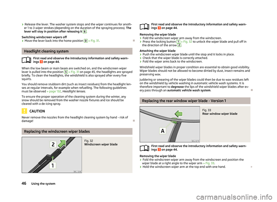
Fig. 32
Windscreen wiper blade
ä
First read and observe the introductory information and safety warn-
ings on page 44.
Removing the wiper blade
›
Fold the windscreen wiper arm away from the windscreen.
› Press the locking button 1
» Fig. 32 to unlock the wiper blade and pull off in
the direction of the arrow 2
.
Attaching the wiper blade
› Push the windscreen wiper blade until the stop and it locks in place.
› Check that the wiper blade is correctly attached.
› Fold the wiper arms back to the windscreen.
Windshield wiper blades in proper condition are essential to obtain good visibility.
Wiper blades should not be allowed to become dirtied by dust, insect remains and
preserving wax.
Juddering or smearing of the wiper blades could then be due to wax residues left
on the windshield by vehicle washing in automatic vehicle wash systems. It is
therefore important to degrease the lips of the windshield wiper blades after ev-
ery pass through an automatic vehicle wash system .Ð Replacing the rear window wiper blade - Version 1
Fig. 33
Rear window wiper blade
First read and observe the introductory information and safety warn-
ings on page 44.
Removing the wiper blade
›
Fold the windscreen wiper arm away from the windscreen and position the
wiper blade at a right angle to the wiper arm » Fig. 33.
› Hold the windscreen wiper arm at the top end with one hand.
£
ä
ä
46 Using the system
Page 66 of 196
Ashtray
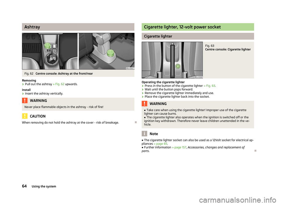
Fig. 62
Centre console: Ashtray at the front/rear
Removing › Pull out the ashtray
» Fig. 62 upwards.
Install
› Insert the ashtray vertically. WARNING
Never place flammable objects in the ashtray - risk of fire! CAUTION
When removing do not hold the ashtray at the cover - risk of breakage. Ð Cigarette lighter, 12-volt power socket
Cigarette lighter
Fig. 63
Centre console: Cigarette lighter
Operating the cigarette lighter › Press in the button of the cigarette lighter
» Fig. 63.
› Wait until the button pops forward.
› Remove the cigarette lighter immediately and use.
› Place the cigarette lighter back into the socket. WARNING
■ Take care when using the cigarette lighter! Improper use of the cigarette
lighter can cause burns. ■ The cigarette lighter also operates when the ignition is switched off or the
ignition key withdrawn. Therefore never leave children unattended in the ve-
hicle. Note
■ The cigarette lighter socket can also be used as a 12Volt socket for electrical ap-
pliances » page 65.
■ Further information » page 157, Accessories, changes and replacement of
parts. Ð
64 Using the system
Page 67 of 196
12-volt power socket
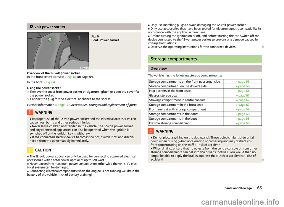
Fig. 64
Boot: Power socket
Overview of the 12-volt power socket
In the front centre console » Fig. 63 on page 64
.
In the boot » Fig. 64.
Using the power socket
› Remove the cover from power socket or cigarette lighter, or open the cover for
the power socket.
› Connect the plug for the electrical appliance to the socket.
Further information » page 157, Accessories, changes and replacement of parts .WARNING
■ Improper use of the 12-volt power socket and the electrical accessories can
cause fires, burns and other serious injuries.
■ Never leave children unattended in the vehicle. The 12-volt power socket
and any connected appliances can also be operated when the ignition is
switched off or the ignition key is withdrawn. ■ If the connected electric device becomes too hot, switch it off and discon-
nect it from the power supply immediately. CAUTION
■ The 12-volt power socket can only be used for connecting approved electrical
accessories with a total power uptake of up to 120
watt.
■ Never exceed the maximum power consumption, otherwise the vehicle's elec-
trical system can be damaged.
■ Connecting electrical components when the engine is not running will drain the
battery of the vehicle - risk of battery draining! ■
Only use matching plugs to avoid damaging the 12-volt power socket.
■ Only use accessories that have been tested for electromagnetic compatibility in
accordance with the applicable directives.
■ Before turning the ignition on or off, and before starting the car, switch off the
device connected to the 12-volt power socket to prevent any damage caused by
voltage fluctuations.
■ Observe the operating instructions for the connected devices! Ð Storage compartments
Overview
The vehicle has the following storage compartments: Storage compartments on the front passenger side » page 66
Storage compartment on the driver's side » page 66
Map pockets in the front seats » page 66
Glasses storage box » page 67
Stowage compartment in centre console » page 67
Storage compartment in the front seat » page 67
Front armrest with storage compartment » page 68
Storage compartments in the doors » page 68
Storage compartments in the boot » page 68
Flexible storage compartment » page 69 WARNING
■ Do not place anything on the dash panel. These objects might slide or fall
down when driving (when accelerating or cornering) and may distract you
from concentrating on the traffic - risk of accident!
■ When driving, ensure that no objects from the centre console or from other
storage compartments can get into the driver's footwell. You would then no
longer be able to apply the brakes, operate the clutch or accelerator - risk of
accident! Ð
65
Seats and Stowage
Page 68 of 196
Storage compartments on the front passenger side
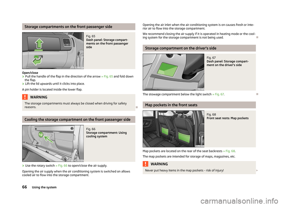
Fig. 65
Dash panel: Storage compart-
ments on the front passenger
side
Open/close
› Pull the handle of the flap in the direction of the arrow
» Fig. 65 and fold down
the flap.
› Lift the lid upwards until it clicks into place.
A pin holder is located inside the lower flap. WARNING
The storage compartments must always be closed when driving for safety
reasons. ÐCooling the storage compartment on the front passenger side
Fig. 66
Storage compartment: Using
cooling system
› Use the rotary switch
» Fig. 66 to open/close the air supply.
Opening the air supply when the air conditioning system is switched on allows
cooled air to flow into the storage compartment. Opening the air inlet when the air conditioning system is on causes fresh or inte-
rior air to flow into the storage compartment.
We recommend closing the air supply if it is operated in heating mode or the cool-
ing system for the storage compartment is not being used. Ð Storage compartment on the driver's side
Fig. 67
Dash panel: Storage compart-
ment on the driver's side
The stowage compartment below the light switch » Fig. 67.Ð Map pockets in the front seats
Fig. 68
Front seat rests: Map pockets
Map pockets are located on the rear of the seat backrests » Fig. 68.
The map pockets are intended for storage of maps, magazines, etc. WARNING
Never put heavy items in the map pockets - risk of injury! £
66 Using the system
Page 72 of 196
Heating and air conditioning system
Heating and air conditioning system
Introductory information
The heating effect is dependent upon the coolant temperature, thus full heat
output only occurs when the engine has reached its operating temperature.
If the cooling system is switched on, the temperature and air humidity drops in
the vehicle. The well-being of the occupants of the car is enhanced as a result of
this particularly at high outside temperatures and a high air humidity. The system
prevents the windows misting up during the cold season of the year.
It is possible to briefly activate recirculated air mode to enhance the cooling ef-
fect.
Please refer to the information regarding recirculated air mode for the air-condi-
tioning system » page 75 or for Climatronic » page 77 .
The air inlet in front of the windscreen must be free of ice, snow or leaves to en-
sure that the heating and cooling system operates properly.
After switching on the cooling Condensation from the evaporator of the air condi-
tioning may drip down and form a puddle below the vehicle. This is quite normal
and not an indication of a leak! WARNING
■ For your own safety and that of other road users, ensure that all the win-
dows are free of ice, snow and misting. Please familiarize yourself about how
to correctly operate the heating and ventilation systems, how to demist and
defrost the windows, as well as with the cooling mode.
■ Do not leave recirculated air mode on over a longer period of time, as “stale”
air can cause fatigue of the driver and passengers, reduce attention levels and
also cause the windows to mist up. The risk of having an accident increases.
Switch off recirculated air mode as soon as the windows start to mist up. Note
■ The used air streams out through the vents in the boot.
■ We recommend that you do not smoke in the vehicle when the recirculating air
mode is operating since the smoke which is drawn at the evaporator from the in-
terior of the vehicle forms deposits in the evaporator of the air conditioning sys-
tem. This produces a permanent odour when the air conditioning system is oper-
ating which can only be eliminated through considerable effort and expense (re-
placement of compressor). ■ To ensure that the heating and air conditioning systems work properly, do not
block up the air outlet vents with any objects. Ð Using the air conditioning system economically
The compressor on the air conditioning system uses power from the engine when
in cooling mode which will effect the fuel consumption.
It recommended to open the windows or the doors of a vehicle for which the inte-
rior has been strongly heated through the effect of direct sunlight in order to al-
low the heated air to escape.
The cooling system should not be switched on while travelling when the window
is open.
If the desired interior temperature can also be achieved without activating the
cooling system, fresh air mode should be selected. For the sake of the environment
Pollutant emissions are also reduced when fuel is saved. Ð Operational problems
If the cooling system does not operate at outside temperatures higher than +5 °C,
there is a problem in the system. The reasons for this may be.
› One of the fuses has blown. Check the fuse and replace if necessa-
ry »
page 168 .
› The cooling system has switched off automatically for a short time because the
coolant temperature of the engine is too hot
» page 9.£
70 Using the system