heater SKODA FABIA 2012 2.G / 5J Owner's Manual
[x] Cancel search | Manufacturer: SKODA, Model Year: 2012, Model line: FABIA, Model: SKODA FABIA 2012 2.G / 5JPages: 196, PDF Size: 4.83 MB
Page 9 of 196
Using the system
Cockpit
Overview
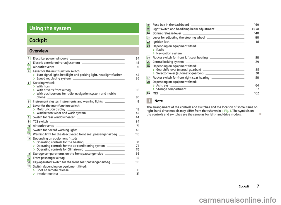
Electrical power windows 34
Electric exterior mirror adjustment 48
Air outlet vents 71
Lever for the multifunction switch:
› Turn signal light, headlight and parking light, headlight flasher 42
› Speed regulating system 86
Steering wheel:
› With horn
› With driver’s front airbag 112
› With pushbuttons for radio, navigation system and mobile
phone 95
Instrument cluster: Instruments and warning lights 8
Lever for the multifunction switch:
› Multifunction display 12
› Windscreen wiper and wash system 45
Switch for rear window heater 44
TCS switch 84
Air outlet vents 71
Switch for hazard warning lights 42
Warning light for the deactivated front seat passenger airbag 115
Depending on equipment fitted:
› Operating controls for the heating 71
› Operating controls for the air conditioning system 73
› Operating controls for Climatronic 76
Storage compartments on the front passenger side 66
Front passenger airbag 112
Key-operated switch for the front seat passenger airbag 115
Switch depending on equipment fitted:
› Boot lid remote release 33
› Interior monitor 311
2
3
4
5
6
7
8
9
10
11
12
13
14
15
16
17 Fuse box in the dashboard 169
Light switch and headlamp beam adjustment 38, 41
Bonnet release lever 140
Lever for adjusting the steering wheel 80
Ignition lock 81
Depending on equipment fitted:
› Radio
› Navigation system
Rocker switch for front left seat heating 50
Central locking system 29
Depending on equipment fitted:
› Gearshift lever (manual gearbox) 85
› Selector lever (automatic gearbox) 91
Rocker switch for front right seat heating 50
Depending on equipment fitted:
› Ashtrays 64
› Storage compartment 67
MDI 102
Note
The arrangement of the controls and switches and the location of some items on
right-hand drive models may differ from that shown in »
Fig. 1. The symbols on
the controls and switches are the same as for left-hand drive models. Ð 18
19
20
21
22
23
24
25
26
27
28
29
7
Cockpit
Page 46 of 196
Boot light
The light comes on automatically when the boot lid is opened. If the lid remains
open for more than about 10
minutes, the boot light switches off automatically. ÐVisibility
Rear window heater
Fig. 29
Switch for rear window heater
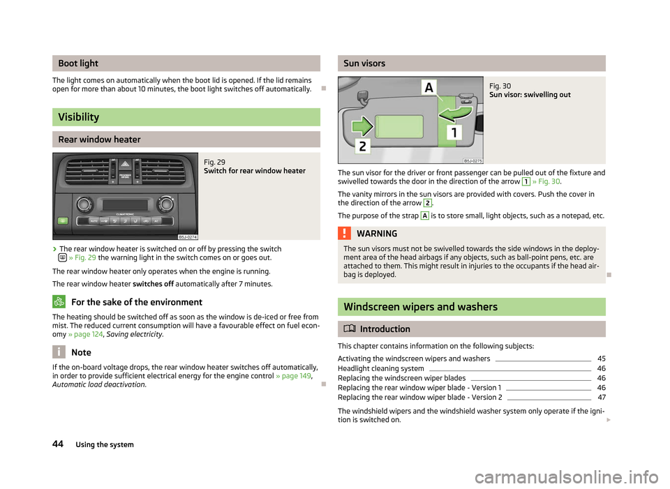
› The rear window heater is switched on or off by pressing the switch
»
Fig. 29
the warning light in the switch comes on or goes out.
The rear window heater only operates when the engine is running.
The rear window heater switches off automatically after 7 minutes. For the sake of the environment
The heating should be switched off as soon as the window is de-iced or free from
mist. The reduced current consumption will have a favourable effect on fuel econ-
omy »
page 124 , Saving electricity .Note
If the on-board voltage drops, the rear window heater switches off automatically,
in order to provide sufficient electrical energy for the engine control »
page 149,
Automatic load deactivation . Ð Sun visors
Fig. 30
Sun visor: swivelling out
The sun visor for the driver or front passenger can be pulled out of the fixture and
swivelled towards the door in the direction of the arrow 1
» Fig. 30.
The vanity mirrors in the sun visors are provided with covers. Push the cover in
the direction of the arrow 2
.
The purpose of the strap A
is to store small, light objects, such as a notepad, etc.
WARNING
The sun visors must not be swivelled towards the side windows in the deploy-
ment area of the head airbags if any objects, such as ball-point pens, etc. are
attached to them. This might result in injuries to the occupants if the head air-
bag is deployed. Ð Windscreen wipers and washers
ä
Introduction
This chapter contains information on the following subjects:
Activating the windscreen wipers and washers 45
Headlight cleaning system 46
Replacing the windscreen wiper blades 46
Replacing the rear window wiper blade - Version 1 46
Replacing the rear window wiper blade - Version 2 47
The windshield wipers and the windshield washer system only operate if the igni-
tion is switched on. £
44 Using the system
Page 50 of 196
Exterior mirror
Fig. 36
Inner part of door: Rotary knob
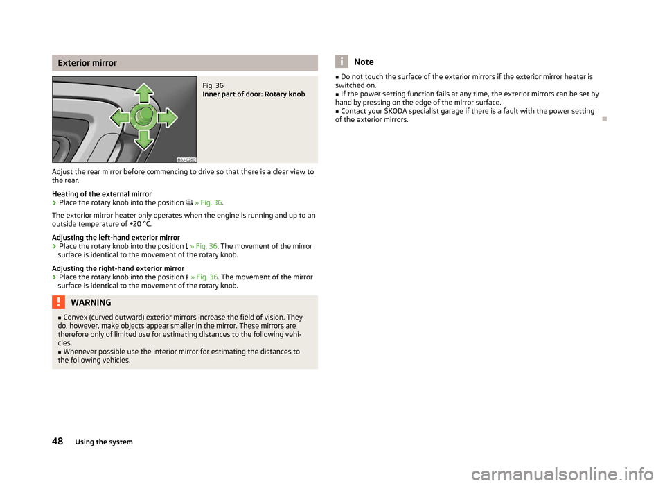
Adjust the rear mirror before commencing to drive so that there is a clear view to
the rear.
Heating of the external mirror
› Place the rotary knob into the position
» Fig. 36.
The exterior mirror heater only operates when the engine is running and up to an
outside temperature of +20 °C.
Adjusting the left-hand exterior mirror
› Place the rotary knob into the position
» Fig. 36. The movement of the mirror
surface is identical to the movement of the rotary knob.
Adjusting the right-hand exterior mirror
› Place the rotary knob into the position
» Fig. 36. The movement of the mirror
surface is identical to the movement of the rotary knob. WARNING
■ Convex (curved outward) exterior mirrors increase the field of vision. They
do, however, make objects appear smaller in the mirror. These mirrors are
therefore only of limited use for estimating distances to the following vehi-
cles.
■ Whenever possible use the interior mirror for estimating the distances to
the following vehicles. Note
■ Do not touch the surface of the exterior mirrors if the exterior mirror heater is
switched on. ■ If the power setting function fails at any time, the exterior mirrors can be set by
hand by pressing on the edge of the mirror surface.
■ Contact your ŠKODA specialist garage if there is a fault with the power setting
of the exterior mirrors. Ð48
Using the system
Page 53 of 196
WARNING
If, as an occupant, you have a subdued pain and/or temperature sensitivity,
e.g. through medication, paralysis or because of chronic illness (e.g. diabetes),
we recommend not to use the seat heating. This can lead to burns on the
back, the posterior and the legs which are difficult to heal. If the seat heating
is used, we recommend to make regular breaks in your journey when driving
long distances, so that the body can recuperate from the stress of the jour-
ney. Please consult your doctor, who can evaluate your specific condition. CAUTION
■ Do not kneel on the seats or otherwise apply pressure at specific points to
avoid damaging the heating elements for the seat heaters.
■ Do not use the seat heaters if the seats are not occupied by persons or if ob-
jects, such as a child seat, bag, etc., are fastened or stored on them. A fault of the
heating elements in the seat heating can occur.
■ Do not clean the seats using moisture » page 134. Note
■ The seat heating should only be switched on when the engine is running. This
has a significant effect of saving on the battery capacity. ■ If the on-board voltage drops, the seat heating is switched off automatically, in
order to provide sufficient electrical energy for the engine control » page 149, Au-
tomatic load deactivation . ÐHead restraints
Fig. 40
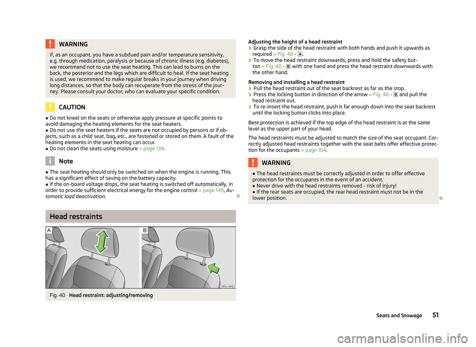
Head restraint: adjusting/removing Adjusting the height of a head restraint
› Grasp the side of the head restraint with both hands and push it upwards as
required » Fig. 40 - .
› To move the head restraint downwards, press and hold the safety but-
ton » Fig. 40 - with one hand and press the head restraint downwards with
the other hand.
Removing and installing a head restraint
› Pull the head restraint out of the seat backrest as far as the stop.
› Press the locking button in direction of the arrow
» Fig. 40 - and pull the
head restraint out.
› To re-insert the head restraint, push it far enough down into the seat backrest
until the locking button clicks into place.
Best protection is achieved if the top edge of the head restraint is at the same
level as the upper part of your head.
The head restraints must be adjusted to match the size of the seat occupant. Cor-
rectly adjusted head restraints together with the seat belts offer effective protec-
tion for the occupants » page 104. WARNING
■ The head restraints must be correctly adjusted in order to offer effective
protection for the occupants in the event of an accident. ■ Never drive with the head restraints removed - risk of injury!
■ If the rear seats are occupied, the rear head restraint must not be in the
lower position. Ð
51
Seats and Stowage
Page 56 of 196
CAUTION
Please ensure that the heating elements for the rear window heater are not dam-
aged as a result of abrasive objects. Note
Tyre pressure must be adjusted to the load » page 151, Service life of tyres .Ð Class N1 vehicles
First read and observe the introductory information and safety warn-
ings on page 53.
On class N1 vehicles, which are not fitted with a protective grille, a lashing set
which complies with the standard EN
12195 (1 - 4) must be used for fastening the
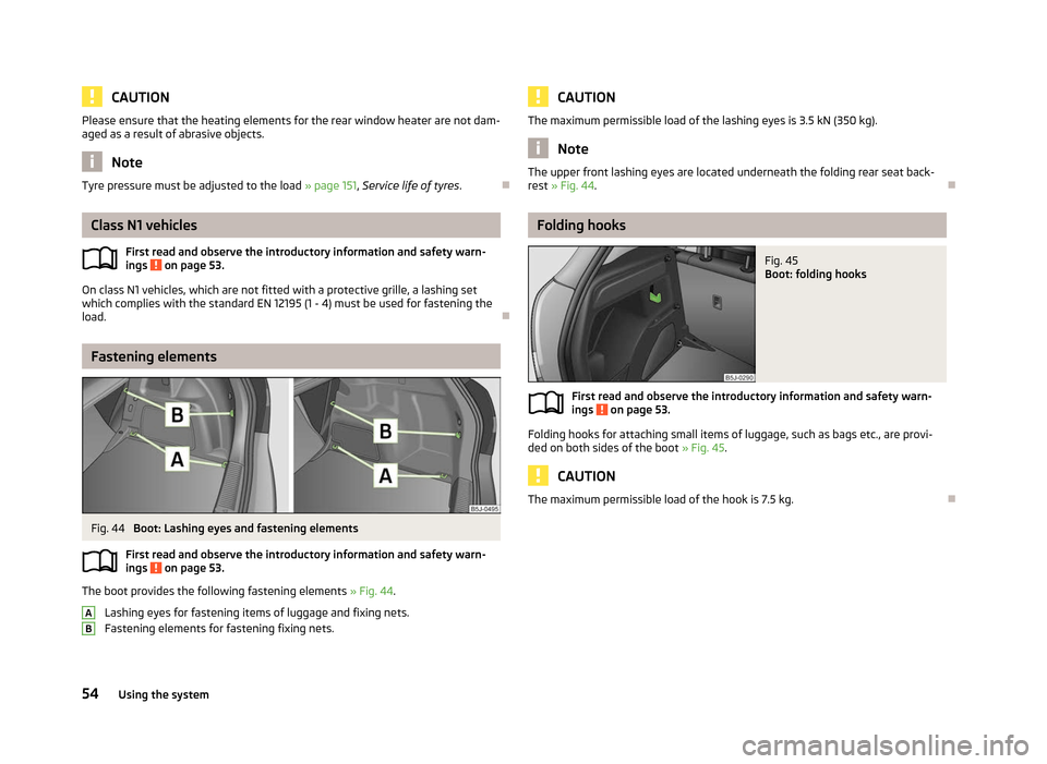
load. ÐFastening elements
Fig. 44
Boot: Lashing eyes and fastening elements
First read and observe the introductory information and safety warn-
ings on page 53.
The boot provides the following fastening elements
»
Fig. 44.
Lashing eyes for fastening items of luggage and fixing nets.
Fastening elements for fastening fixing nets.
ä
ä A
B CAUTION
The maximum permissible load of the lashing eyes is 3.5 kN (350 kg). Note
The upper front lashing eyes are located underneath the folding rear seat back-
rest » Fig. 44. Ð Folding hooks
Fig. 45
Boot: folding hooks
First read and observe the introductory information and safety warn-
ings on page 53.
Folding hooks for attaching small items of luggage, such as bags etc., are provi-
ded on both sides of the boot
» Fig. 45. CAUTION
The maximum permissible load of the hook is 7.5 kg. Ð
ä
54 Using the system
Page 134 of 196
De-icing windows and exterior mirrors
First read and observe the introductory information and safety warn-
ings on page 129.
Use a plastic ice scraper for removing snow and ice from the windows and mir-
rors. The ice scraper should not be moved forward and backward but in one direc-
tion to avoid any damage to the surface of the glass.
Clean the windows from the inside on a regular basis.
Dry the glass surfaces with a clean chamois leather or a cloth intended for this
purpose.
When drying the windows after washing the vehicle, do not use window leathers
that have been used to polish the bodywork. Residues of preservatives in the
window leather can dirty the window and reduce visibility. CAUTION
■ Never remove snow or ice from glass parts using warm or hot water - risk of for-
mation of cracks in the glass!
■ When removing snow or ice from windows and mirror lenses ensure that the
paintwork of the vehicle is not to damage.
■ Snow or ice that is contaminated with coarse dirt such as fine gravel, sand, and
salt must not be removed from the window glass and mirrors - risk of damage to
the surface of the windows and mirrors. ÐRadio reception and aerial
First read and observe the introductory information and safety warn-
ings on page 129.
Car parks, tunnels, tall buildings or mountains can disrupt the radio signal even
causing it to fail completely.
With factory-fitted radios and navigation systems, the aerial for the radio recep-
tion can be installed at different locations in the vehicle:
› on the inside of the rear window along with the rear window heater;
› on the inside of the rear side windows;
› on the inside of the windscreen;
› on the roof. Ð
ä
ä Headlight lenses
First read and observe the introductory information and safety warn-
ings on page 129.
Use soap and clean water to clean the plastic headlight lenses.
CAUTION
■ Never wipe the headlights dry and do not use any sharp objects to clean the
plastic lenses, this may damage the protective paintwork and consequently cause
the formation of cracks on the headlight lenses.
■ Do not use any aggressive cleaning or chemical solvent products to clean the
headlights - risk of damaging the headlight lenses. Ð Rubber seals
First read and observe the introductory information and safety warn-
ings on page 129.
The rubber seals on doors, the sliding roof and other windows remain smoother
and last longer if the seals are treated regularly with a suitable rubber care prod-
uct. This helps to prevent leakages and premature wear of the seals. Rubber
seals which are well cared for also do not stick together in cold winter weather.
Ð Door lock cylinders
First read and observe the introductory information and safety warn-
ings on page 129.
Specific products must be used for de-icing door lock cylinders.
Note
■ When washing your vehicle, ensure as little water as possible gets into the lock-
ing cylinders. ■ We recommend that suitable materials from ŠKODA Original Accessories are
used for maintaining the door lock cylinders. Ð
ä
ä
ä
132 General Maintenance
Page 144 of 196
Changing engine oil
First read and observe the introductory information and safety warn-
ings on page 138.
The engine oil must be changed at the intervals stated in the Service schedule or
according to the service interval indicator
» page 10, Service Interval Display.CAUTION
Additives must not be added to the engine oil - risk of causing considerable dam-
age to parts of the engine! Damage, which results from such product, are exclu-
ded from the warranty. Note
If your skin has come into contact with oil, it must be washed thoroughly. ÐCoolant
First read and observe the introductory information and safety warn-
ings on page 138.
The cooling system is filled with a coolant in the factory.
The coolant consists of water with a concentration of coolant additive of 40 %.
This mixture provides antifreeze protection down to -25
°C and also protects the
cooling and heating system from corrosion. It also prevents the formation of scale
and significantly increases the boiling point of the coolant.
The concentration of coolant must therefore not be reduced by adding water dur-
ing the summer months or in countries with a warm climate. The concentration of
coolant additive in the coolant must be at least 40 %.
If a higher concentration of antifreeze is required for climatic reasons, the amount
of coolant additive can only be increased up to 60 % (antifreeze protection down
to approx. -40 °C). The antifreeze protection tails off above that concentration.
Vehicles exported to countries with a cold climate are already factory-filled with a
coolant which offers antifreeze protection down to about -35 °C. In these coun-
tries the concentration of coolant additive should be at least 50 %.
When refilling, we only recommend you use the same antifreeze written on the
antifreeze expansion tank » Fig. 120 on page 143.
ä
ä
Coolant capacity
Petrol engines Capacities (in litres)
1.2 l/44 kW 5.5
1.2 l/51 kW 5.5
1.2 ltr./63 kW TSI 7.7
1.2 ltr./77 kW TSI 7.7
1.4 l/63 kW 5.5
1.4 ltr./132 kW TSI 6.6
1.6 l/77 kW 5.5 Diesel engines
Capacities (in litres)
1.2 ltr./55 kW TDI CR DPF 6.6
1.6 ltr./55 kW TDI CR DPF 8.4
1.6 ltr./66 kW TDI CR DPF 8.4
1.6 ltr./77 kW TDI CR DPF 8.4 CAUTION
■ Other coolant additives that do not comply with the correct specifications can
above all significantly reduce the anticorrosion effect.
■ Any faults resulting from corrosion may cause a loss of coolant and can conse-
quently result in major engine damage! Note
On vehicles that are fitted with an auxiliary heater (auxiliary heating and ventila-
tion), the coolant capacity is approx. 1 l larger. Ð
142 General Maintenance
Page 151 of 196
Automatic load deactivation
First read and observe the introductory information and safety warn-
ings on page 145.
An intelligent vehicle power management system automatically takes various
measures at high loads on the vehicle battery to prevent discharging of the bat-
tery: This manifests itself by the following:
› The idling speed is raised to allow the generator to deliver more electricity to
the electrical system.
› Where appropriate large consumers of power, e.g. seat heaters, rear window
heaters, voltage supply to the 12V power socket, have their power limited or in
case of emergency shut off completely. Note
Despite such intervention by the vehicle electric system management, the vehicle
battery may be drained. For example, when the ignition is switched on a long time
with the engine turned off or the side or parking lights are turned on during lon-
ger parking. Driving comfort is not put at risk by any shutting off of consumers.
Often the driver is not aware of it having taken place. Ðä
149
Inspecting and replenishing
Page 171 of 196
Fuses in the dash panel
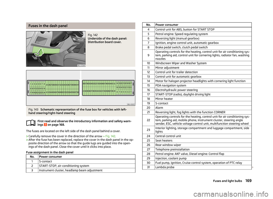
Fig. 142
Underside of the dash panel:
Distribution board cover. Fig. 143
Schematic representation of the fuse box for vehicles with left-
hand steering/right-hand steering
First read and observe the introductory information and safety warn-
ings on page 168.
The fuses are located on the left side of the dash panel behind a cover.
›
Carefully remove the cover in the direction of the arrow
» Fig. 142.
› After the fuse has been replaced, replace the cover in the dash panel in the op-
posite direction of the arrow so that the guide lugs are guided into the open-
ings of the dash panel. Close the cover until it clicks into place.
Fuse assignment in the dash panel No. Power consumer
1 S-contact
2 START-STOP, air-conditioning system
3 Instrument cluster, headlamp beam adjustment ä No. Power consumer
4 Control unit for ABS, button for START STOP5 Petrol engine: Speed regulating system
6 Reversing light (manual gearbox) 7 Ignition, engine control unit, automatic gearbox
8 Brake pedal switch, clutch pedal switch
9 Operating controls for the heating, control unit for air conditioning sys-
tem, parking aid, control unit for cornering lights, radiator fan, washing
nozzles
10 Windscreen Wiper and Washer System 11 Mirror adjustment
12 Control unit for trailer detection
13 Control unit for automatic gearbox
14 Motor for halogen projector headlights with cornering light function 15 PDA navigation system
16 Electrohydraulic power steering 17 START-STOP (radio), daylight driving light
18 Mirror heater 19 S-contact
20 Alarm 21 Reversing light, fog lights with the function CORNER
22 Operating controls for the heating, control unit for air conditioning sys-
tem, parking aid, mobile phone, instrument cluster, steering angle
sender, ESC, vehicle voltage control unit, multifunction steering wheel
23 Interior lighting, storage compartment and luggage compartment, side
lights
24 Central control unit 25 Seat heaters
26 Rear window wiper 27 Telephone preinstallation
28 Petrol engine: AKF valve, Diesel engine: Control flap 29 Injection, coolant pump
30 Fuel pump, ignition, Cruise control system, operation of PTC relay 31 Lambda probe £ 169
Fuses and light bulbs
Page 172 of 196
No. Power consumer
32 High pressure fuel pump, pressure valve
33 Engine control unit
34 Engine control unit, vacuum pump 35 Power supply of ignition lock
36 Main beam 37 Rear fog light, DC/DC converter START-STOP
38 Fog lights 39 Air blower for heating
40-41 Not assigned 42 Rear window heater
43 Horn
44 Windscreen wipers 45 Central control unit for convenience system
46 Engine control unit, fuel pump 47 Cigarette lighter, power socket in the luggage compartment
48 ABS, START-STOP (DC/DC) converter ESP 49 Turn signal lights, brake lights50 START-STOP (DC/DC) converter infotainment, radio 51 Electrical power window (front and rear) - left side
52 Electrical power window (front and rear) - right side
53 Parking light = left side, electrical sliding/tilting roof
54 START-STOP (instrument cluster), alarm 55 Control unit for automatic gearbox
56 Headlight cleaning system, parking light - right side 57 Left low beam, headlight range adjustment
58 Low beam on the right Ð Fuses in the engine compartment
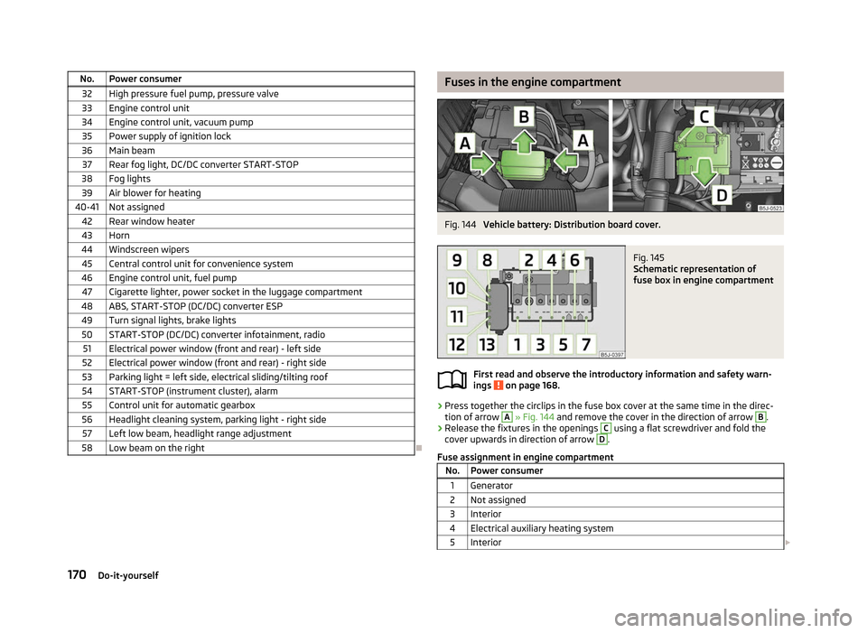
Fig. 144
Vehicle battery: Distribution board cover. Fig. 145
Schematic representation of
fuse box in engine compartment
First read and observe the introductory information and safety warn-
ings on page 168.
›
Press together the circlips in the fuse box cover at the same time in the direc-
tion of arrow A
» Fig. 144
and remove the cover in the direction of arrow B
.
› Release the fixtures in the openings C
using a flat screwdriver and fold the
cover upwards in direction of arrow D
.
Fuse assignment in engine compartment No. Power consumer
1 Generator
2 Not assigned
3 Interior
4 Electrical auxiliary heating system 5 Interior £ ä
170 Do-it-yourself