air condition SKODA FABIA 2013 2.G / 5J User Guide
[x] Cancel search | Manufacturer: SKODA, Model Year: 2013, Model line: FABIA, Model: SKODA FABIA 2013 2.G / 5JPages: 223, PDF Size: 12.77 MB
Page 82 of 223
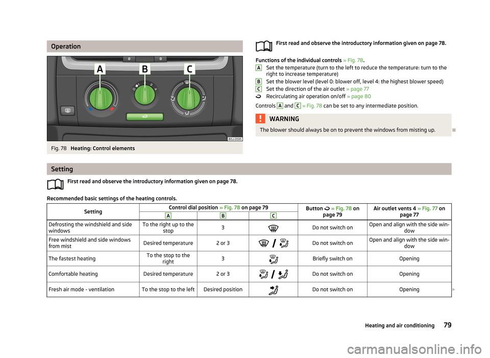
OperationFig. 78
Heating: Control elements
First read and observe the introductory information given on page 78.
Functions of the individual controls » Fig. 78 .
Set the temperature (turn to the left to reduce the temperature: turn to the right to increase temperature)
Set the blower level (level 0: blower off, level 4: the highest blower speed) Set the direction of the air outlet » page 77
Recirculating air operation on/off » page 80
Controls
A
and
C
» Fig. 78 can be set to any intermediate position.
WARNINGThe blower should always be on to prevent the windows from misting up.
ABC
Setting
First read and observe the introductory information given on page 78.
Recommended basic settings of the heating controls.
SettingControl dial position » Fig. 78 on page 79Button » Fig. 78 on
page 79Air outlet vents 4 » Fig. 77 on
page 77ABCDefrosting the windshield and side
windowsTo the right up to the stop3Do not switch onOpen and align with the side win- dowFree windshield and side windows
from mistDesired temperature2 or 3
Do not switch onOpen and align with the side win-
dowThe fastest heatingTo the stop to theright3Briefly switch onOpeningComfortable heatingDesired temperature2 or 3
Do not switch onOpeningFresh air mode - ventilationTo the stop to the leftDesired positionDo not switch onOpening 79Heating and air conditioning
Page 83 of 223
We recommend that you leave the air outlet vents 3 » Fig. 77 on page 77 in the
open position in all operating modes.
Note
If the air distribution is directed only towards the windows, the total amount of
air is used to defrost the windows and thus no air will be fed to the footwell. This
can limit the heating comfort.
Recirculated air mode
First read and observe the introductory information given on page 78.
Recirculated air mode prevents polluted air from outside the vehicle getting into
the vehicle, for example when driving through a tunnel or when standing in a
traffic jam.
Switching on/off
›
Press the
button.
The indicator light in the button lights up.
›
Press the
button again.
The indicator light in the button goes out.
Recirculated air mode is switched off automatically if the air distribution control
C
» Fig. 78 on page 79 is turned to the
position. Recirculated air mode can be
switched on again from this setting by pressing the
button again.
WARNINGNever leave recirculated air mode on over a longer period, as “stale air” can
cause fatigue in the driver and the passengers, reduce attention levels and al-
so cause the windows to mist up. The risk of having an accident increases.
Switch off recirculated air mode as soon as the windows start to mist up.
Air conditioning system (manual air conditioning
system)
Introduction
This chapter contains information on the following subjects: Operation
81
Setting the air conditioning system
82
Recirculated air mode
82
The cooling system operates only if the following conditions are met. The cooling system is switched on » page 81.
The engine is running.
The outside temperature is above approximately +2 °C.
The blower switch is switched on (positions 1-4).
If the desired interior temperature can also be achieved without activating the cooling system, fresh air mode should be selected.
If the coolant temperature is too high, the cooling system is switched off to en-
sure that the engine cools down.
CAUTION
■ Under certain circumstances, air at a temperature of about 5 °C can flow out of
the vents when the cooling system is switched on.■
Lengthy and uneven distribution of the air flow out of the vents (especially
around the feet) and large differences in temperature, for example, when getting
out of the vehicle, can cause susceptible individuals to catch a cold.
Note
We recommend that you have the air conditioning system cleaned by a specialist
garage once every year.80Using the system
Page 84 of 223
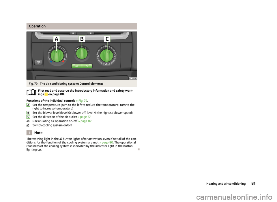
OperationFig. 79
The air conditioning system: Control elements
First read and observe the introductory information and safety warn- ings
on page 80.
Functions of the individual controls » Fig. 79 .
Set the temperature (turn to the left to reduce the temperature: turn to the right to increase temperature)
Set the blower level (level 0: blower off, level 4: the highest blower speed)
Set the direction of the air outlet » page 77
Recirculating air operation on/off » page 82
Switch cooling system on/off
Note
The warning light in the button lights after activation, even if not all of the con-
ditions for the function of the cooling system are met » page 80. The operational
readiness of the cooling system is indicated by the indicator light in the button
lighting up.
ABC81Heating and air conditioning
Page 85 of 223
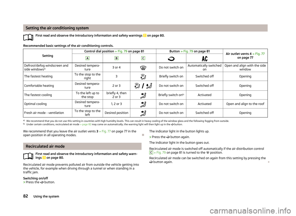
Setting the air conditioning systemFirst read and observe the introductory information and safety warnings
on page 80.
Recommended basic settings of the air conditioning controls.
SettingControl dial position » Fig. 79 on page 81Button » Fig. 79 on page 81Air outlet vents 4 » Fig. 77
on page 77ABC
Defrost/defog windscreen and
side windows a)Desired tempera-
ture3 or 4Do not switch onAutomatically switched onOpen and align with the sidewindowThe fastest heatingTo the stop to theright3Briefly switch onSwitched offOpeningComfortable heatingDesired tempera-
ture2 or 3
Do not switch onSwitched offOpeningThe fastest coolingTo the left up to
the stopbriefly 4, then 2 or 3Briefly switch on b)ActivatedOpeningOptimal coolingDesired tempera-
ture1, 2 or 3Do not switch onActivatedOpen and align to the roofFresh air mode - ventilationTo the stop to the leftDesired positionDo not switch onSwitched offOpeninga)
We recommend that you do not use this setting in countries with high humidity levels. This can result in heavy cooling of the window glass and the following fogging from outside.
b)
Under certain conditions, recirculated air mode » page 82 may come on automatically; the warning light will then light up in the
button.
We recommend that you leave the air outlet vents
3 » Fig. 77 on page 77 in the
open position in all operating modes.
Recirculated air mode
First read and observe the introductory information and safety warn-ings
on page 80.
Recirculated air mode prevents polluted air from outside the vehicle getting into
the vehicle, for example when driving through a tunnel or when standing in a traffic jam.
Switching on/off
›
Press the
button.
The indicator light in the button lights up.›
Press the button again.
The indicator light in the button goes out.
Recirculated air mode is switched off automatically if the air distribution control
C
» Fig. 79 on page 81 is turned to the position.
Recirculated air mode can be switched on again from this setting by pressing the
button again.
82Using the system
Page 86 of 223
WARNINGNever leave recirculated air mode on over a longer period, as “stale air” can
cause fatigue in the driver and the passengers, reduce attention levels and al- so cause the windows to mist up. The risk of having an accident increases.Switch off recirculated air mode as soon as the windows start to mist up.
Climatronic (automatic air conditioning system)
Introduction
This chapter contains information on the following subjects:
Control elements
83
Automatic mode
84
Setting the temperature
84
Recirculated air mode
84
Controlling the blower
85
Defrosting windscreen
85
Climatronic in automatic mode ensures the best-possible setting of the tempera-
ture of the outflowing air, the blower stage and air distribution.
The system also takes sunlight into account, which eliminates the need to alterthe settings manually.
The cooling system operates only if the following conditions are met. The cooling system is switched on » page 83.
The engine is running.
The outside temperature is above approximately +2 °C.
If the coolant temperature is too high, the cooling system is switched off to en- sure that the engine cools down.
Note
We recommend that you have Climatronic cleaned by a specialist garage once ev-
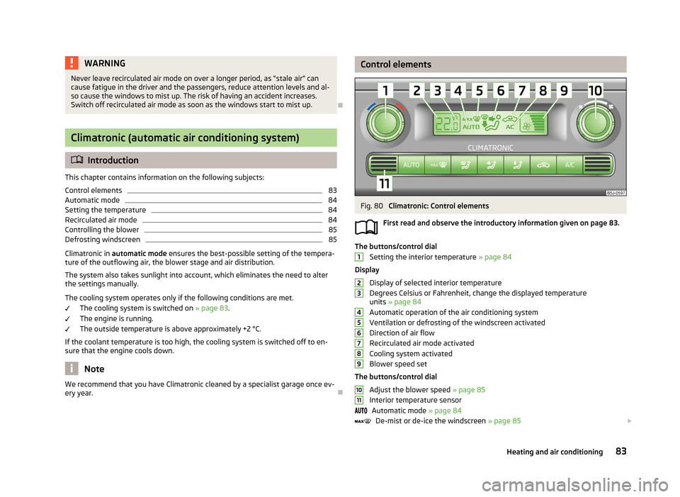
ery year.Control elementsFig. 80
Climatronic: Control elements
First read and observe the introductory information given on page 83.
The buttons/control dial Setting the interior temperature » page 84
Display
Display of selected interior temperature
Degrees Celsius or Fahrenheit, change the displayed temperature units » page 84
Automatic operation of the air conditioning system Ventilation or defrosting of the windscreen activated
Direction of air flow
Recirculated air mode activated
Cooling system activated
Blower speed set
The buttons/control dial Adjust the blower speed » page 85
Interior temperature sensor Automatic mode » page 84
De-mist or de-ice the windscreen » page 85
123456789101183Heating and air conditioning
Page 88 of 223
NoteIf recirculated air mode is switched on for around 15 minutes, the symbol will
begin to flash in the display as a sign that the recirculated air mode is switched on long-term. If the recirculated air mode is not switched off, the symbol flashes for
around 5 minutes.
Controlling the blower
First read and observe the introductory information given on page 83.
The Climatronic system controls the blower stages automatically in line with the
interior temperature. However, the blower level can be manually adjusted to suit your particular needs.
›
Turn control dial
10
» Fig. 80 on page 83 to the left or to the right to increase or
decrease the blower speed.
If the blower is switched off, the Climatronic system is switched off.
The blower speed set is indicated by displaying the corresponding number of seg- ments in icon
9
» Fig. 80 on page 83 in the display.
WARNING■
“Stale air” may result in fatigue in the driver and occupants, reduce attention
levels and also cause the windows to mist up. The risk of having an accident
increases.■
Do not switch off the Climatronic system for longer than necessary.
■
Switch on the Climatronic system as soon as the windows mist up.
Defrosting windscreen
First read and observe the introductory information given on page 83.
Switching on
›
Press the
button » Fig. 80 on page 83.
Switching off
›
Press the
button » Fig. 80 on page 83 again or press the
button.
More air flows out of the air outlet vents 1 and 2 » Fig. 77 on page 77. The temper-
ature control is controlled automatically.
85Heating and air conditioning
Page 101 of 223
›Depress and hold the clutch pedal (vehicles with a manual gearbox) or brake
pedal (vehicles with an automatic gearbox) until the engine starts.›
Turn the key to position
3
to the stop and release immediately the engine has
started – do not depress the accelerator.
After letting go, the vehicle key will return to position
2
.
›
Release the handbrake.
If the engine does not start within 10 seconds, turn the key to position
1
. Repeat
the start-up process after approx. half a minute.
Switching off the engine
First read and observe the introductory information and safety warn-ings
on page 96.
Switch off the engine by turning the ignition key to position
1
» Fig. 86 on
page 97.
Brakes
Introduction
This chapter contains information on the following subjects:
Information for braking
98
Handbrake
99WARNING■ Greater physical effort is required for braking when the engine is switched
off – there is the risk of an accident.■
The clutch pedal must be depressed when braking on a vehicle with manual
transmission, when the vehicle is in gear and at low revs. If you fail to do so, the functionality of the brake servo can be impaired – there is the risk of an
accident.WARNING (Continued)■ If a front spoiler, full wheel trim, etc. is mounted retrospectively, it must be
ensured that the air supply to the front wheel brakes is not reduced. The front
brakes may overheat, which can have a negative impact on the functioning of
the braking system – there is a risk of an accident.■
Never leave children unattended in the vehicle. The children might, for ex-
ample, release the handbrake or take the vehicle out of gear. The vehicle might then move off – there is the risk of an accident.
CAUTION
■ Observe the recommendations on the new brake pads » page 104.■Never let the brakes slip with light pressure on the pedal if braking is not neces-
sary. This causes the brakes to overheat and can also result in a longer braking distance and excessive wear.
Information for braking
First read and observe the introductory information and safety warn-
ings
on page 98.
If the brakes are applied in full and the control unit for the braking system consid-
ers the situation to be dangerous for the following traffic, the brake light flashes
automatically.
After the speed was reduced below around 10 km/h or the vehicle was stopped,
the brake light stops flashing and the hazard warning light system switches on.
The hazard warning light system is switched off automatically after accelerating
or driving off again.
Before travelling a long distance down a steep gradient, reduce speed and shift
into the next lowest gear. As a result, the braking effect of the engine will be
used, reducing the load on the brakes. Any additional braking should be comple-
ted intermittently, not continuously.
Wear-and-tear
The wear of the brake pads is dependent on the operating conditions and driving style.
The brake pads wear more quickly if a lot of journeys are completed in towns and
over short distances or if a very sporty style of driving is adopted.
98Driving
Page 111 of 223
›Minimum fuel leakage during accidents.
› Reduced noise.
Choice of materials › Extensive use of recyclable material.
› Air conditioning filled with CFC-free refrigerant.
› No cadmium.
› No asbestos.
› Reduction in the “vaporisation” of plastics.
Manufacture › Solvent-free cavity protection.
› Solvent-free protection of the vehicle for transportation from the production
plant to the customer.
› The use of solvent-free adhesives.
› No CFCs used in the production process.
› Without use of mercury.
› Use of water-soluble paints.
Trade-in and recycling of old cars
ŠKODA meets the requirements of the brand and its products with regard to pro- tecting the environment and the preserving resources. All new ŠKODA vehicles
can be utilized up to 95 % and always 1)
be returned.
In a lot of countries sufficient trade-in networks have been created, where you
can trade-in your vehicle. After you trade-in your vehicle, you will receive a confir-
mation stating the recycling in accordance with environmental regulations.
Note
Detailed information about the trade-in and recycling of end-of-life cars is availa-
ble from a specialist garage.
Avoiding damage to your vehicle
Introduction
This chapter contains information on the following subjects:
General information
108
Driving through water on streets
109
General information
First read and observe the introductory information given on page 108.
Pay attention to low-slung parts of the vehicle, such as the spoiler and exhaust,particularly in the following situations.
› When driving on poorly maintained roads and tracks.
› When driving over kerb stones.
› When driving on steep ramps, etc.
Particular attention is necessary for vehicle with a sports suspension and when then vehicle is fully laden.
1)
Subject to fulfilment of the national legal requirements.
108Driving
Page 112 of 223
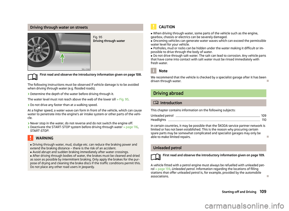
Driving through water on streetsFig. 95
Driving through water
First read and observe the introductory information given on page 108.
The following instructions must be observed if vehicle damage is to be avoided
when driving through water (e.g. flooded roads).
›
Determine the depth of the water before driving through it.
The water level must not reach above the web of the lower sill » Fig. 95.
›
Do not drive any faster than at a walking speed.
At a higher speed, a water wave can form in front of the vehicle, which can cause
water to penetrate into the engine's air intake system or other parts of the vehi- cle.
›
Never stop in the water, do not reverse and do not switch the engine off.
›
Deactivate the START-STOP system before driving through water » page 116,
START-STOP .
WARNING■
Driving through water, mud, sludge etc. can reduce the braking power and
extend the braking distance – there is the risk of an accident.■
Avoid abrupt and sudden braking immediately after water crossings.
■
After driving through bodies of water, the brakes must be cleaned and dried
as soon as possible by intermittent braking. Only apply the brakes for the pur-
pose of drying and cleaning the brake discs if the traffic conditions permit this.
Do not place any other road users in jeopardy.
CAUTION■ When driving through water, some parts of the vehicle such as the engine,
gearbox, chassis or electrics can be severely damaged.■
Oncoming vehicles can generate water waves which can exceed the permissible
water level for your vehicle.
■
Potholes, mud or rocks can be hidden under the water making it difficult or im-
possible to drive through the body of water.
■
Do not drive through salt water. The salt can lead to corrosion. Any vehicle parts
that have come into contact with salt water must be rinsed immediately with
fresh water.
Note
We recommend that the vehicle is checked by a specialist garage after it has been
driven through water.
Driving abroad
Introduction
This chapter contains information on the following subjects:
Unleaded petrol
109
Headlights
110
In certain countries, it may be possible that the ŠKODA service partner network is
limited or has not been established. This is the reason why procuring certain
spare parts may be somewhat complicated and specialist garages may only be
able to make limited repairs.
Unleaded petrol
First read and observe the introductory information given on page 109.
A vehicle fitted with a petrol engine must always be refuelled with unleaded pet-
rol » page 159 , Unleaded petrol . Information regarding the locations of filling
stations that offer unleaded petrol is, for example, provided by the automobile
associations.
109Starting-off and Driving
Page 116 of 223
XDL function (Fabia RS and Fabia Estate RS only)
XDL is an extension to the electronic differential lock. XDL does not respond to
traction, but to the relief of the inner front wheel during fast cornering. The active
brake intervention on the brake of the inner wheel prevents it from spinning.
Thus, the traction is improved and the vehicle continues to follow the desired
track.
Parking aid
Introduction
This chapter contains information on the following subjects:
Function
113
Activation/deactivation
114WARNING■ The parking aid is not a substitute for the driver paying proper attention and
it is always the driver's responsibility to take care when reversing the vehicle
or carrying out similar manoeuvres. Pay particular attention to small children
and animals as they are not recognised by the parking aid sensors.■
Before reversing, you should make sure that there are no small obstacles,
such as rocks, thin posts, trailer drawbars etc. behind your vehicle. Such ob-
stacles may not be recognised by the parking aid sensors.
■
Under certain circumstances, surfaces of certain objects and types of cloth-
ing cannot reflect the system signals. Thus, these objects or people who wear
such clothing are not recognised by the System sensors.
■
External sound sources can have a detrimental effect on the system. Under
adverse conditions, this may cause objects or people to not be recognised by the system.
CAUTION
■ If a warning signal sounds for about 3 seconds after activating the system and
there is no obstacle close to your car, this indicates a system fault. Have the fault
rectified by a specialist garage.■
The sensors must be kept clean (free of ice, etc.) to enable the parking aid to
operate properly.
■ Under adverse weather conditions (heavy rain, water vapour, very low or high
temperatures etc.) system function may be limited.■
Additionally fitted modules, such as a bicycle rack, can impair the function of the
parking aid.
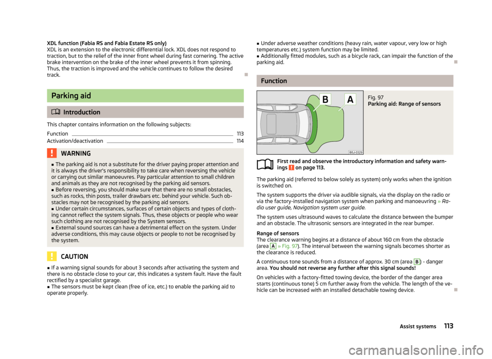
Function
Fig. 97
Parking aid: Range of sensors
First read and observe the introductory information and safety warn- ings on page 113.
The parking aid (referred to below solely as system) only works when the ignition
is switched on.
The system supports the driver via audible signals, via the display on the radio or
via the factory-installed navigation system when parking and manoeuvring » Ra-
dio user guide, Navigation system user guide.
The system uses ultrasound waves to calculate the distance between the bumper
and an obstacle. The ultrasonic sensors are integrated in the rear bumper.
Range of sensors
The clearance warning begins at a distance of about 160 cm from the obstacle
(area
A
» Fig. 97 ). The interval between the warning signals becomes shorter as
the clearance is reduced.
A continuous tone sounds from a distance of approx. 30 cm (area
B
) - danger
area. You should not reverse any further after this signal sounds!
On vehicles with a factory-fitted towing device, the border of the danger area starts (continuous tone) 5 cm further away from the vehicle. The length of the ve-
hicle can be increased with an installed detachable towing device.
113Assist systems