window SKODA FABIA 2013 2.G / 5J User Guide
[x] Cancel search | Manufacturer: SKODA, Model Year: 2013, Model line: FABIA, Model: SKODA FABIA 2013 2.G / 5JPages: 223, PDF Size: 12.77 MB
Page 42 of 223
Note■After switching the ignition off, it is still possible to open or close the windows
for approx. 10 minutes. The electrical power windows are only switched off com- pletely once the driver's door or front passenger door are opened.■
When driving always use the existing heating, air conditioning and ventilation
system for ventilating the interior of the vehicle. If the windows are opened, dust
as well as other dirt can get into the vehicle and in addition the wind noise is
more at certain speeds.
Opening/closing the windows
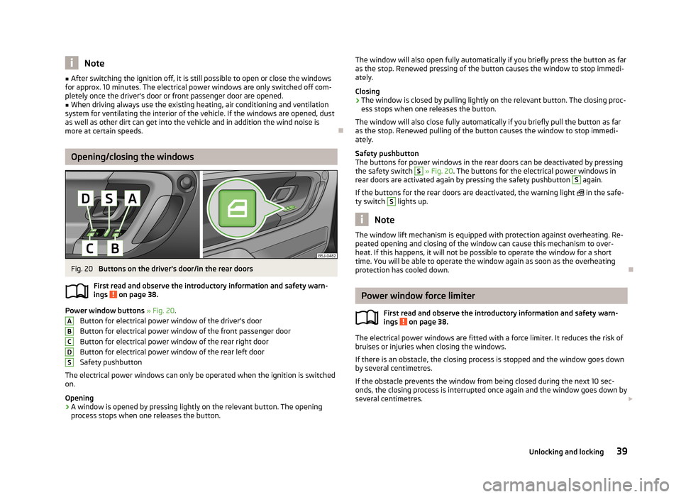
Fig. 20
Buttons on the driver's door/in the rear doors
First read and observe the introductory information and safety warn-
ings
on page 38.
Power window buttons » Fig. 20 .
Button for electrical power window of the driver's door
Button for electrical power window of the front passenger door
Button for electrical power window of the rear right door Button for electrical power window of the rear left door
Safety pushbutton
The electrical power windows can only be operated when the ignition is switched
on.
Opening
›
A window is opened by pressing lightly on the relevant button. The opening process stops when one releases the button.
ABCDSThe window will also open fully automatically if you briefly press the button as far
as the stop. Renewed pressing of the button causes the window to stop immedi- ately.
Closing›
The window is closed by pulling lightly on the relevant button. The closing proc-
ess stops when one releases the button.
The window will also close fully automatically if you briefly pull the button as far as the stop. Renewed pulling of the button causes the window to stop immedi-
ately.
Safety pushbutton
The buttons for power windows in the rear doors can be deactivated by pressing
the safety switch
S
» Fig. 20 . The buttons for the electrical power windows in
rear doors are activated again by pressing the safety pushbutton
S
again.
If the buttons for the rear doors are deactivated, the warning light
in the safe-
ty switch
S
lights up.
Note
The window lift mechanism is equipped with protection against overheating. Re-
peated opening and closing of the window can cause this mechanism to over-
heat. If this happens, it will not be possible to operate the window for a short
time. You will be able to operate the window again as soon as the overheating
protection has cooled down.
Power window force limiter
First read and observe the introductory information and safety warn-
ings
on page 38.
The electrical power windows are fitted with a force limiter. It reduces the risk of
bruises or injuries when closing the windows.
If there is an obstacle, the closing process is stopped and the window goes down
by several centimetres.
If the obstacle prevents the window from being closed during the next 10 sec-
onds, the closing process is interrupted once again and the window goes down by several centimetres.
39Unlocking and locking
Page 43 of 223
If you attempt to close the window again within 10 seconds of the window being
moved down for the second time, even though the obstacle was not yet been re- moved, the closing process is only stopped. During this time it is not possible toautomatically close the window. The force limiter is still switched on.
The force limiter is only switched off if you attempt to close the window again
within the next 10 seconds - the window will now close with full force!
If you wait longer than 10 seconds, the force limiter is switched on again.
Window convenience operation
First read and observe the introductory information and safety warn-ings
on page 38.
The electrical power windows can be opened and closed as follows when unlock-ing and locking the vehicle.
Opening
›
Press the
button on the remote control key and hold.
›
Hold the key in the driver's lock in the unlock position.
›
Hold button
A
1)
in the opening position » Fig. 20 on page 39.
Closing
›
Press the
button on the remote control key and hold.
›
Hold the key in the driver's lock in the lock position.
›
Hold button
A
1)
in the closing position » Fig. 20 on page 39.
You can interrupt the opening or closing process for the windows immediately by releasing the key or the lock button.
Operational faults
First read and observe the introductory information and safety warn-
ings
on page 38.
Electrical power windows do not operate
If the battery has been disconnected and then reconnected while the window was opened, the electrical power windows will not operate. The system must be
activated. Proceed as follows to re-establish the function.
› Switch on the ignition.
› Pull the top edge of the button in the driver's door and close the window.
› Release the button.
› Pull the relevant button upwards again for another approximately 3 seconds
and hold.
Operation in winter
In the winter, ice on the window may cause greater resistance as the window is
closed. The window will stop and open again by several centimetres.
It is necessary to deactivate the force limiter to close the window » page 39.
Electric sliding/tilting roof
Introduction
This chapter contains information on the following subjects:
Operation
41
Comfort operation
41
Emergency operation
42
The sliding/tilting roof is operated with the rotary switch » Fig. 21 on page 41
and only works when the ignition is switched on. The control dial has several po- sitions.
The sliding/tilting roof can still be opened, closed and tilted for approx. 10 mi-
nutes after switching the ignition off. However, as soon as one of the front doors
is opened it is no longer possible to operate the sliding/tilting roof.
1)
Convenience opening and closing the windows with the button
A
is possible immediately after un-
locking the vehicle or turning off the ignition and opening the driver's or front passenger's door.
40Using the system
Page 52 of 223
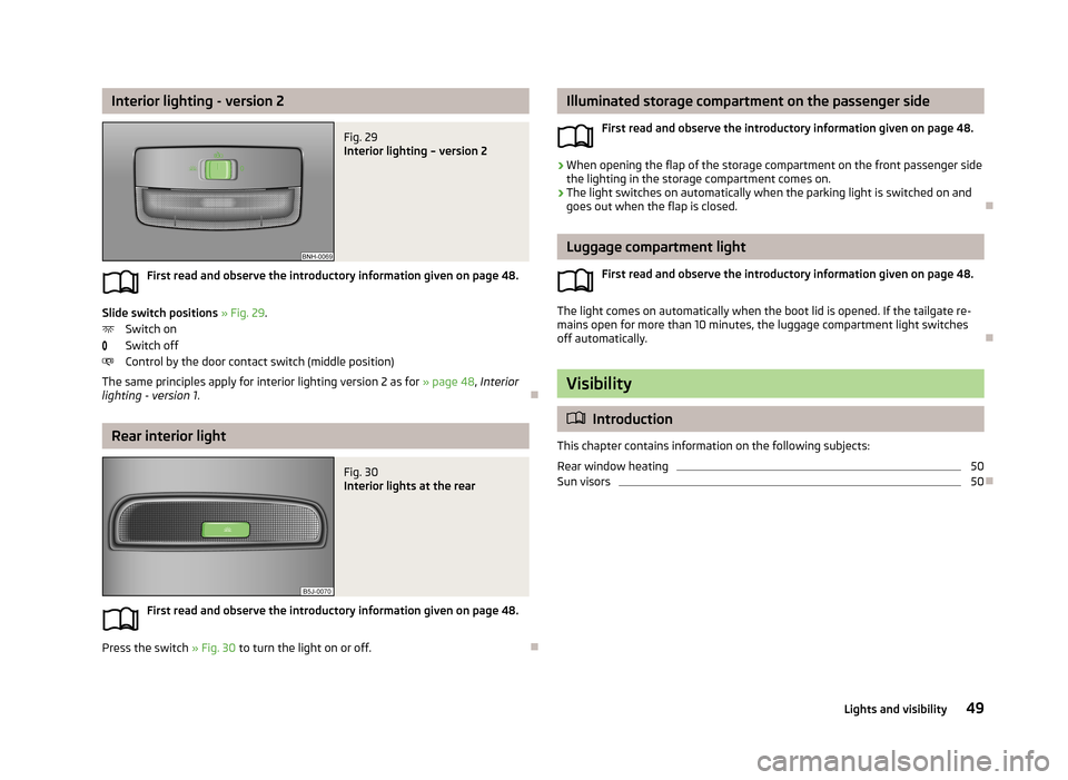
Interior lighting - version 2Fig. 29
Interior lighting – version 2
First read and observe the introductory information given on page 48.
Slide switch positions » Fig. 29 .
Switch on
Switch off
Control by the door contact switch (middle position)
The same principles apply for interior lighting version 2 as for » page 48, Interior
lighting - version 1 .
Rear interior light
Fig. 30
Interior lights at the rear
First read and observe the introductory information given on page 48.
Press the switch » Fig. 30 to turn the light on or off.
Illuminated storage compartment on the passenger side
First read and observe the introductory information given on page 48.›
When opening the flap of the storage compartment on the front passenger side
the lighting in the storage compartment comes on.
›
The light switches on automatically when the parking light is switched on and
goes out when the flap is closed.
Luggage compartment light
First read and observe the introductory information given on page 48.
The light comes on automatically when the boot lid is opened. If the tailgate re-
mains open for more than 10 minutes, the luggage compartment light switches
off automatically.
Visibility
Introduction
This chapter contains information on the following subjects:
Rear window heating
50
Sun visors
50
49Lights and visibility
Page 53 of 223
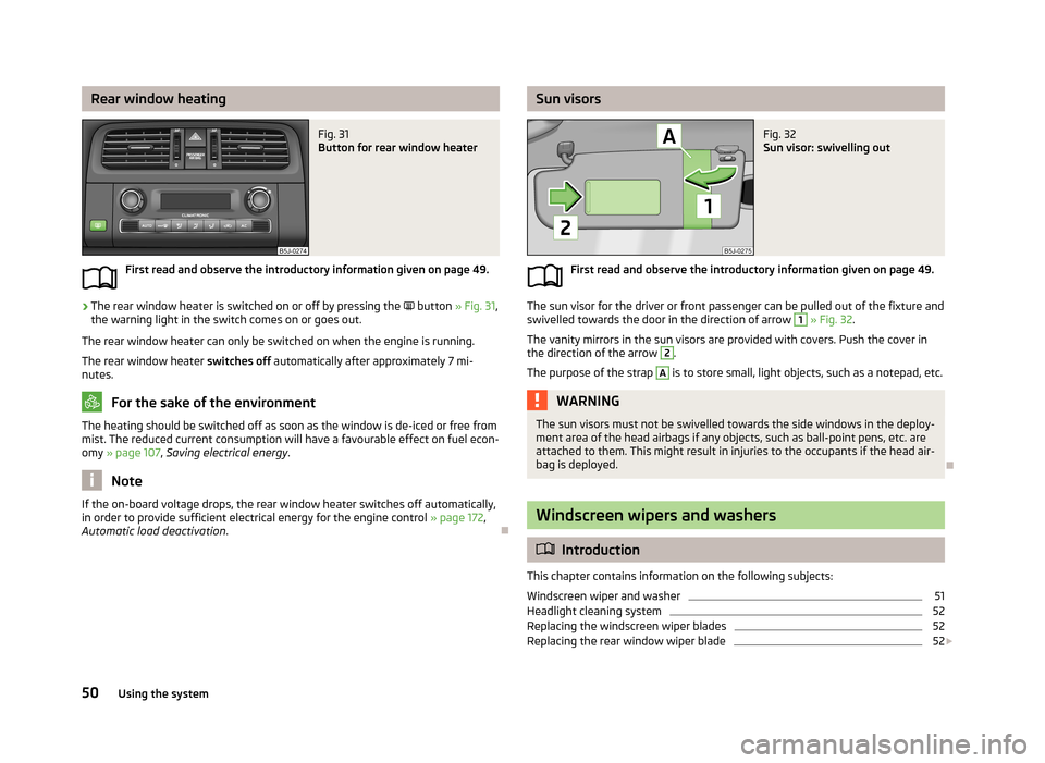
Rear window heatingFig. 31
Button for rear window heater
First read and observe the introductory information given on page 49.
›
The rear window heater is switched on or off by pressing the
button » Fig. 31 ,
the warning light in the switch comes on or goes out.
The rear window heater can only be switched on when the engine is running.
The rear window heater switches off automatically after approximately 7 mi-
nutes.
For the sake of the environment
The heating should be switched off as soon as the window is de-iced or free from
mist. The reduced current consumption will have a favourable effect on fuel econ-
omy » page 107 , Saving electrical energy .
Note
If the on-board voltage drops, the rear window heater switches off automatically,
in order to provide sufficient electrical energy for the engine control » page 172,
Automatic load deactivation .
Sun visorsFig. 32
Sun visor: swivelling out
First read and observe the introductory information given on page 49.
The sun visor for the driver or front passenger can be pulled out of the fixture and
swivelled towards the door in the direction of arrow
1
» Fig. 32 .
The vanity mirrors in the sun visors are provided with covers. Push the cover in the direction of the arrow
2
.
The purpose of the strap
A
is to store small, light objects, such as a notepad, etc.
WARNINGThe sun visors must not be swivelled towards the side windows in the deploy-
ment area of the head airbags if any objects, such as ball-point pens, etc. are attached to them. This might result in injuries to the occupants if the head air-
bag is deployed.
Windscreen wipers and washers
Introduction
This chapter contains information on the following subjects:
Windscreen wiper and washer
51
Headlight cleaning system
52
Replacing the windscreen wiper blades
52
Replacing the rear window wiper blade
52
50Using the system
Page 54 of 223
The windscreen wipers and the windscreen washer system only operate when
the ignition is switched on.
The rear window is wiped once automatically if the windscreen wipers are on when reverse gear is selected.
Top up with windscreen wiper fluid » page 163.WARNING■
Properly maintained windscreen wiper blades are essential for clear visibility
and safe driving » page 52.■
Do not use the windscreen washer system at low temperatures, without
heating the windscreen beforehand. Otherwise the window cleaner could
freeze on the windscreen and restrict the view to the front.
■
Replace the windscreen wiper blades once or twice a year for safety rea-
sons. These can be purchased from a ŠKODA Partner.
CAUTION
■ In cold temperatures and during the winter, check before the journey or before
switching on the ignition that the wiper blades are not frozen to the windscreen. If the windscreen wipers are switched on when the blades are frozen to the
windscreen, this may damage both the blades and windscreen wiper motor!■
If the ignition is switched off while the windscreen wipers are switched on, the
windscreen wipers will continue wiping in the same mode after the ignition is
turned back on. The windscreen wipers could freeze up in cold temperatures be- tween the time the ignition was turned off and when it was turned back on again.
■
Carefully detach frozen wiper blades from the front or rear window.
■
Remove snow and ice from the windscreen wipers before driving.
■
If the windscreen wipers are handled carelessly, there is a risk of damage to the
windscreen.
Note
■ The windscreen washer nozzles for the windscreen are heated when the en-
gine is running and the outside temperature is less than approx. +10 °C.■
The content of the windscreen washer fluid reservoir is 3.5 litres. On vehicles
fitted with the headlight cleaning system, the volume is around 5.4 litres.
■
The wiper blades should be cleaned on a regular basis with a windscreen clean-
er to avoid any smears. The wiper blades should be cleaned with a sponge or
cloth if they are heavily soiled by insect residues, for example.
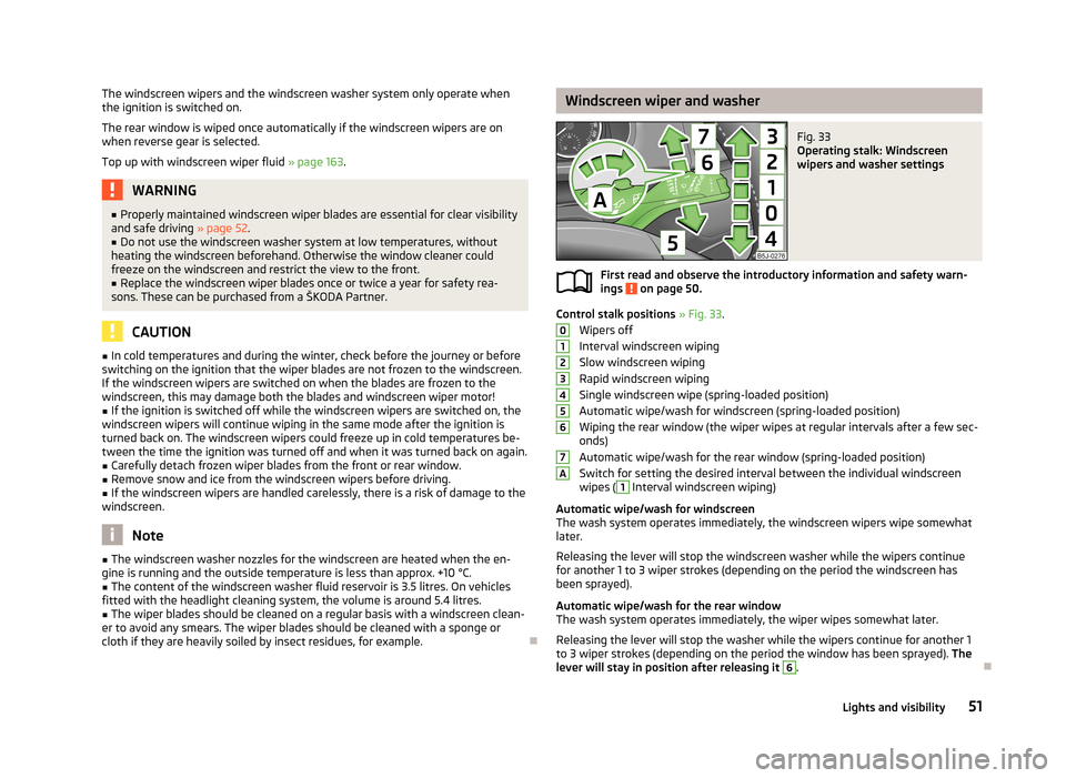
Windscreen wiper and washerFig. 33
Operating stalk: Windscreen
wipers and washer settings
First read and observe the introductory information and safety warn-
ings on page 50.
Control stalk positions » Fig. 33 .
Wipers off
Interval windscreen wiping
Slow windscreen wiping
Rapid windscreen wiping
Single windscreen wipe (spring-loaded position)
Automatic wipe/wash for windscreen (spring-loaded position) Wiping the rear window (the wiper wipes at regular intervals after a few sec-
onds)
Automatic wipe/wash for the rear window (spring-loaded position)
Switch for setting the desired interval between the individual windscreen wipes (
1
Interval windscreen wiping)
Automatic wipe/wash for windscreen
The wash system operates immediately, the windscreen wipers wipe somewhat
later.
Releasing the lever will stop the windscreen washer while the wipers continue
for another 1 to 3 wiper strokes (depending on the period the windscreen has
been sprayed).
Automatic wipe/wash for the rear window The wash system operates immediately, the wiper wipes somewhat later.
Releasing the lever will stop the washer while the wipers continue for another 1
to 3 wiper strokes (depending on the period the window has been sprayed). The
lever will stay in position after releasing it
6
.
01234567A51Lights and visibility
Page 55 of 223
Headlight cleaning systemFirst read and observe the introductory information and safety warn-
ings
on page 50.
The headlights are sprayed briefly if the low beam or main beam are switched on
and the windscreen wiper stalk is pulled to position
5
» Fig. 33 on page 51. To
clean the headlights, the windshield is also sprayed after every five squirts.
You should remove stubborn dirt (such as insect residues) from the headlight len-
ses at regular intervals, for example when refuelling. The following guidelines
must be observed » page 154, Headlight lenses .
To ensure the proper operation of the cleaning system during the winter, any
snow should be removed from the washer nozzle fixtures and ice should be
cleared with a de-icing spray.
CAUTION
Never remove the nozzles from the headlight cleaning system by hand – there is
risk of damage.
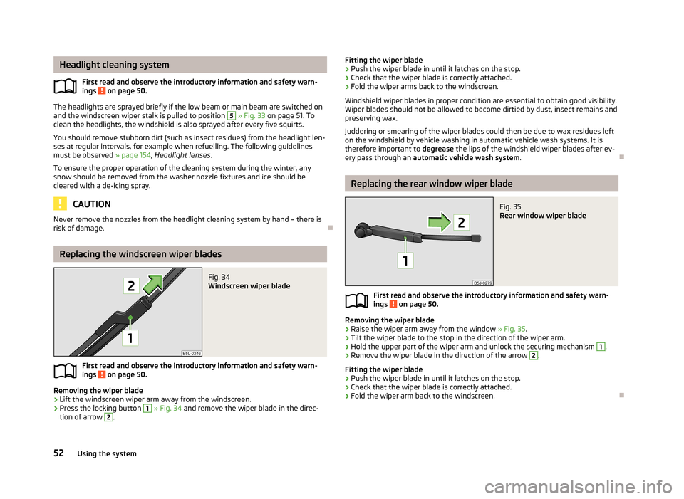
Replacing the windscreen wiper blades
Fig. 34
Windscreen wiper blade
First read and observe the introductory information and safety warn- ings on page 50.
Removing the wiper blade
›
Lift the windscreen wiper arm away from the windscreen.
›
Press the locking button
1
» Fig. 34 and remove the wiper blade in the direc-
tion of arrow
2
.
Fitting the wiper blade›Push the wiper blade in until it latches on the stop.›
Check that the wiper blade is correctly attached.
›
Fold the wiper arms back to the windscreen.
Windshield wiper blades in proper condition are essential to obtain good visibility.
Wiper blades should not be allowed to become dirtied by dust, insect remains and
preserving wax.
Juddering or smearing of the wiper blades could then be due to wax residues left on the windshield by vehicle washing in automatic vehicle wash systems. It is
therefore important to degrease the lips of the windshield wiper blades after ev-
ery pass through an automatic vehicle wash system .
Replacing the rear window wiper blade
Fig. 35
Rear window wiper blade
First read and observe the introductory information and safety warn-
ings on page 50.
Removing the wiper blade
›
Raise the wiper arm away from the window » Fig. 35.
›
Tilt the wiper blade to the stop in the direction of the wiper arm.
›
Hold the upper part of the wiper arm and unlock the securing mechanism
1
.
›
Remove the wiper blade in the direction of the arrow
2
.
Fitting the wiper blade
›
Push the wiper blade in until it latches on the stop.
›
Check that the wiper blade is correctly attached.
›
Fold the wiper arm back to the windscreen.
52Using the system
Page 56 of 223
Rear window
Introduction
This chapter contains information on the following subjects:
Manually dimmed rear-view mirror
53
Exterior mirrors
53WARNING■ Make sure that the mirror is not covered by ice, snow, condensation or other
objects.■
Convex (curved outward) or aspheric exterior mirrors increase the field of vi-
sion. They do, however, make objects appear smaller in the mirror. These mir-
rors are therefore only of limited use for estimating distances to the following vehicles.
■
Whenever possible use the interior mirror for estimating the distances to
the following vehicles.
Manually dimmed rear-view mirror
First read and observe the introductory information and safety warn-ings
on page 53.
Basic setting
›
Pull the lever on the lower edge of the mirror away from the windscreen.
Dimming mirror
›
Push the lever on the lower edge of the mirror towards the windscreen.
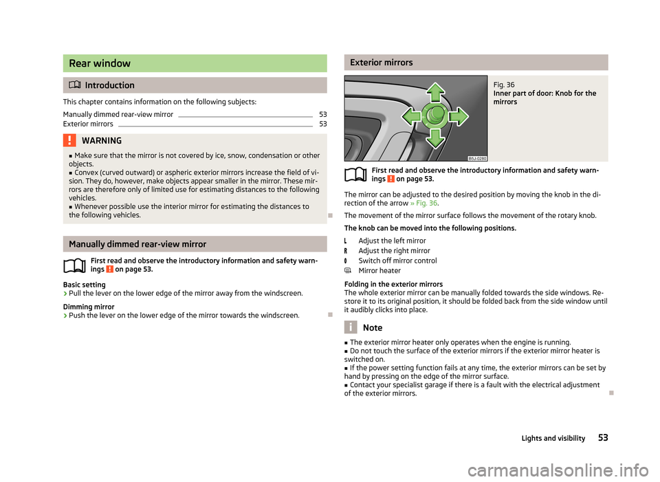
Exterior mirrorsFig. 36
Inner part of door: Knob for the
mirrors
First read and observe the introductory information and safety warn-
ings on page 53.
The mirror can be adjusted to the desired position by moving the knob in the di-
rection of the arrow » Fig. 36.
The movement of the mirror surface follows the movement of the rotary knob.
The knob can be moved into the following positions.
Adjust the left mirror
Adjust the right mirror
Switch off mirror control
Mirror heater
Folding in the exterior mirrors
The whole exterior mirror can be manually folded towards the side windows. Re- store it to its original position, it should be folded back from the side window until
it audibly clicks into place.
Note
■ The exterior mirror heater only operates when the engine is running.■Do not touch the surface of the exterior mirrors if the exterior mirror heater is
switched on.■
If the power setting function fails at any time, the exterior mirrors can be set by
hand by pressing on the edge of the mirror surface.
■
Contact your specialist garage if there is a fault with the electrical adjustment
of the exterior mirrors.
53Lights and visibility
Page 57 of 223
Seats and storage
Front seats
Introduction
This chapter contains information on the following subjects:
Adjusting the front seats - Version 1
55
Adjusting the front seats - Variant 2
55
Front seat heating
55
The driver's seat should be adjusted in such a way that the pedals can be fully
pressed to the floor with slightly bent legs.
The seat backrest on the driver's seat should be adjusted in such a way that the
upper point of the steering wheel can be easily reached with slightly bent arms.
Correct adjustment of the seats is particularly important:
› for reaching the controls safely and quickly;
› for a relaxed, fatigue-free body position;
› for achieving maximum protection from the seat belts and the airbag system.
WARNINGGeneral information■Caution when adjusting the seat! You may suffer injuries or bruises as a re-
sult of adjusting the seat without paying proper attention.■
The seat backrests must not be reclined too far when driving otherwise this
will affect proper operation of the seat belts and of the airbag system – risk of
injury.
■
Never carry more people than the number of seats in the vehicle.
■
Each occupant must correctly fasten the seat belt belonging to the seat.
Children must be fastened » page 140, Transporting children safely with a
suitable restraint system.
■
The front seats and head restraints must be adjusted to match the body
size at all times and the seat belt must always be fastened properly to provide the most effective levels of protection to the passengers.
■
Do not transport any objects on the front passenger seat other than objects
(e.g. child safety seat) intended for this purpose – there is the risk of an acci-
dent.
WARNINGInformation for the driver■Only adjust the driver's seat when the vehicle is stationary – there is the risk
of an accident.■
Keep a distance of at least 25 cm from the steering wheel. Not keeping to
this minimum distance will mean that the airbag system will not be able to
properly protect you – risk of death.
■
Ensure that there are no objects in the driver's footwell as they may get
caught behind the pedals while you are driving or under braking. You would
then no longer be able to operate the clutch, brake or accelerate.
WARNINGInformation for the front seat passenger■Maintain a distance of at least 25 cm from the dash panel. Not maintaining
this minimum distance will mean that the airbag system will not be able to
properly protect you - there is a risk that you could be killed.■
Always keep your feet in the footwell when the car is being driven - never
place your feet on the instrument panel, out of the window or on the seats.
You will be exposed to increased risk of injury if it becomes necessary to apply
the brakes or in the event of an accident. You may suffer fatal injuries when
an airbag is deployed if you have adopted an incorrect seating position.
Note
After a certain time, play can develop within the adjustment mechanism of the
backrest angle.
54Using the system
Page 62 of 223
WARNING (Continued)■Please note that the handling properties of the vehicle may be affected
when transporting heavy objects as the centre of gravity can be shifted –
there is a risk of an accident. The speed and style of driving must be adjusted
accordingly.■
If the items of luggage or objects are attached to the lashing eyes with un-
suitable or damaged lashing straps, injuries can occur in the event of braking
manoeuvres or accidents. To prevent items of luggage from being thrown for-
ward, always use suitable lashing straps which must be firmly attached to the lashing eyes.
■
Items carried in the luggage compartment must be stowed in such a way
that no objects are able to slip forward under sudden driving manoeuvres or
braking – there is a risk of injury.
■
When transporting fastened objects which are sharp and dangerous in the
boot that has been enlarged by folding the rear seats forward, ensure the safety of the passengers transported on the other rear seats » page 126, Cor-
rect seated position of the rear seat passengers .
■
If the rear seat next to the folded forward seat is occupied, ensure maxi-
mum safety, e.g. by placing the goods to be transported in such a way that the
seat is prevented from folding back in case of a rear collision.
■
Never drive with the tailgate fully opened or slightly ajar otherwise exhaust
gases may get into the interior of the vehicle – risk of poisoning.
■
Under no circumstances, should the permissible axle loads and permissible
gross weight of the vehicle be exceeded – there is the risk of an accident.
■
Never transport people in the boot!
CAUTION
Please ensure that the heating elements for the rear window heater are not dam-
aged as a result of abrasive objects.
Note
Tyre pressure must be adjusted to the load » page 174
, Tyre service life .
Class N1 vehicles
First read and observe the introductory information and safety warn-
ings
on page 58.
On class N1 vehicles, which are not fitted with a protective grille, a lashing set which complies with the standard EN 12195 (1 - 4) must be used for fastening the
load.
The proper functioning of the electrical system is essential for the safe operation
of the vehicle. It is important to ensure that it is not damaged during modifica-
tions or when loading or unloading the luggage compartment.
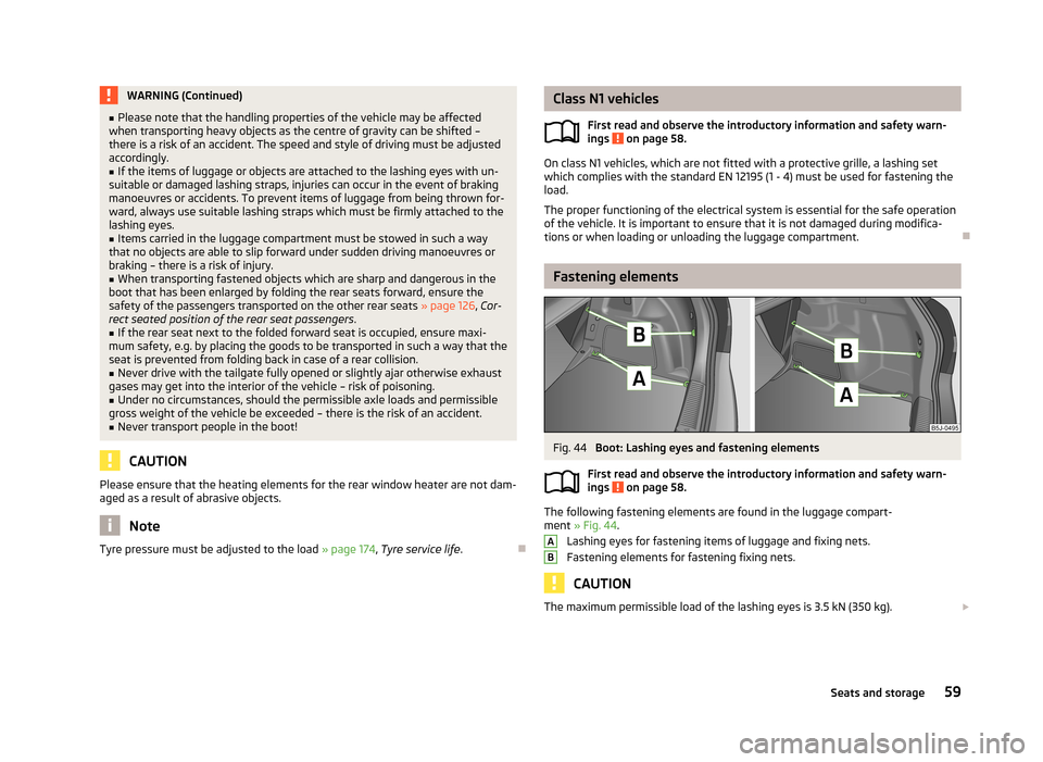
Fastening elements
Fig. 44
Boot: Lashing eyes and fastening elements
First read and observe the introductory information and safety warn- ings
on page 58.
The following fastening elements are found in the luggage compart-ment » Fig. 44 .
Lashing eyes for fastening items of luggage and fixing nets.
Fastening elements for fastening fixing nets.
CAUTION
The maximum permissible load of the lashing eyes is 3.5 kN (350 kg). AB59Seats and storage
Page 70 of 223
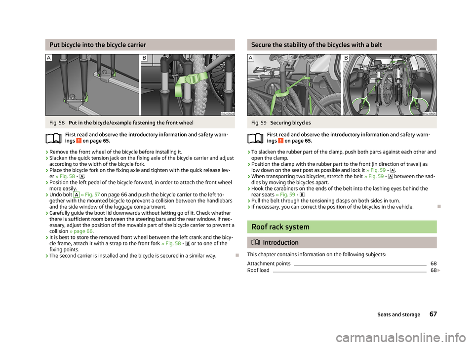
Put bicycle into the bicycle carrierFig. 58
Put in the bicycle/example fastening the front wheel
First read and observe the introductory information and safety warn-
ings
on page 65.
›
Remove the front wheel of the bicycle before installing it.
›
Slacken the quick tension jack on the fixing axle of the bicycle carrier and adjust
according to the width of the bicycle fork.
›
Place the bicycle fork on the fixing axle and tighten with the quick release lev- er » Fig. 58 -
.
›
Position the left pedal of the bicycle forward, in order to attach the front wheel
more easily.
›
Undo bolt
A
» Fig. 57 on page 66 and push the bicycle carrier to the left to-
gether with the mounted bicycle to prevent a collision between the handlebars
and the side window of the luggage compartment.
›
Carefully guide the boot lid downwards without letting go of it. Check whether there is sufficient room between the steering bars and the rear window. If nec-essary, adjust the position of the movable part of the bicycle carrier to prevent a
collision » page 66 .
›
It is best to store the removed front wheel between the left crank and the bicy-
cle frame, attach it with a strap to the front fork » Fig. 58 -
or to one of the
fixing points.
›
The second carrier is installed and the bicycle is secured in a similar way.
Secure the stability of the bicycles with a beltFig. 59
Securing bicycles
First read and observe the introductory information and safety warn-
ings
on page 65.
›
To slacken the rubber part of the clamp, push both parts against each other and
open the clamp.
›
Position the clamp with the rubber part to the front (in direction of travel) as low down on the seat post as possible and lock it » Fig. 59 -
.
›
When transporting two bicycles, stretch the belt » Fig. 59 -
between the sad-
dles by moving the bicycles apart.
›
Hook the carabiners on the ends of the belt into the lashing eyes behind the rear seats » Fig. 59 -
.
›
Pull the belt through the tensioning clasps on both sides in turn.
›
If necessary, you can correct the position of the bicycles in the vehicle.
Roof rack system
Introduction
This chapter contains information on the following subjects:
Attachment points
68
Roof load
68
67Seats and storage