instrument cluster SKODA FABIA 2013 2.G / 5J Owner's Guide
[x] Cancel search | Manufacturer: SKODA, Model Year: 2013, Model line: FABIA, Model: SKODA FABIA 2013 2.G / 5JPages: 223, PDF Size: 12.77 MB
Page 171 of 223
If the coolant level in the coolant expansion tank is too low, this is indicated by
the warning light lighting up in the instrument cluster » page 22, Coolant .
We still recommend inspecting the coolant level directly at the reservoir from
time to time.
Loss of coolant
A loss of coolant is first and foremost an indication of a leak in the system. Do
not merely top up the coolant. Have the cooling system checked by a specialist
garage.
Replenishing
First read and observe the introductory information and safety warn-
ings
on page 166.
Only top up with new coolant.
›
Switch off the engine.
›
Allow the engine to cool.
›
Place a cloth over the cap of the coolant expansion tank and carefully unscrew
the cap.
›
Replenish the coolant.
›
Turn the cap until it clicks into place.
Do not use an alternative additive if the specified coolant is not available in an emergency. In this case, just use water and have the correct mixing ratio of waterand the coolant additive restored by a specialist garage as soon as possible.
Do not fill the coolant above the mark
A
(max.) » Fig. 128 on page 167. Excess
coolant heats up and then is forced out of the cooling system through the pres-
sure relief valve in the cap.
Brake fluid
Introduction
This chapter contains information on the following subjects:
Level check
168
Changing
169WARNING■ The engine compartment of your car is a hazardous area. While working in
the engine compartment, be sure to observe the following warn- ings » page 160 .■
Do not continue your journey if the fluid level has fallen below the MIN
marking » Fig. 129 on page 168 - there is a risk of an accident. Seek help from
a specialist garage.
■
Do not use used brake fluid - the function of the brake system may be im-
paired – there is the risk of an accident.
CAUTION
Brake fluid damages the paintwork of the vehicle.
Note
The brake fluid is changed as part of a prescribed inspection service.
Level check
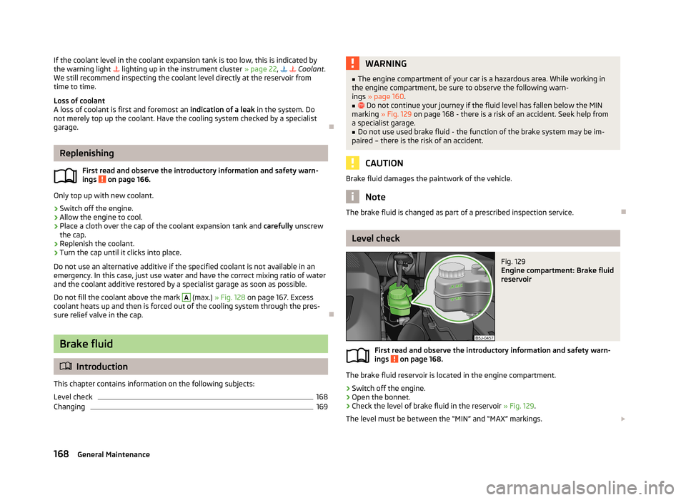
Fig. 129
Engine compartment: Brake fluid
reservoir
First read and observe the introductory information and safety warn-
ings on page 168.
The brake fluid reservoir is located in the engine compartment.
›
Switch off the engine.
›
Open the bonnet.
›
Check the level of brake fluid in the reservoir » Fig. 129.
The level must be between the “MIN” and “MAX” markings.
168General Maintenance
Page 172 of 223
A slight drop in the fluid level results in operation due to normal wear and tear
and the automatic adjustment of the brake pads.
There may be an indication of a leak in the brake system, however, if the fluid lev-
el drops significantly within a short time or if it drops below the “MIN” marking.
If the brake fluid level is too low, this is indicated by the warning light lighting
up in the instrument cluster » page 20, Brake system .
Changing
First read and observe the introductory information and safety warn-ings
on page 168.
Brake fluid absorbs moisture. Over time it therefore absorbs moisture from the
environment.
Excessive water in the brake fluid may be the cause of corrosion in the brake sys-
tem.
The water content lowers the boiling point of the brake fluid.
The brake fluid must comply with the following standards or specifications: › VW 50114;
› FMVSS 116 DOT4.
Vehicle battery
Introduction
This chapter contains information on the following subjects:
Open cover
170
Checking the electrolyte level
171
Operation in winter
171
Charging
171
Disconnecting or reconnecting
172
Replacing
172
Automatic load deactivation
172Warning symbols on the vehicle batterySymbolMeaningAlways wear eye protection.Battery acid is severely caustic. Always wear gloves and eye protec- tion.Keep fire, sparks, open flames and lit cigarettes well clear of the ve-
hicle battery.When charging the vehicle battery, a highly explosive gas mixture is
produced.Keep children away from the vehicle battery.WARNINGThere is a risk of injuries, poisoning, chemical burns, explosions or fire when
carrying out any work on the battery and on the electrical system. It is essen-
tial to comply with the generally applicable rules of safety as well as the warn- ing instructions outlined below.■
Keep children away from the vehicle battery.
■
Do not tilt the battery otherwise battery electrolyte may flow out of the bat-
tery vent openings. Protect your eyes by wearing safety glasses or a face
shield – there is a risk of being blinded.
■
Always wear protective gloves, eye and skin protection when handling the
vehicle battery.
■
The battery acid is strongly corrosive and must, therefore, be handled with
the greatest of care.
■
Corrosive fumes in the air irritate the air passages and lead to conjunctivitis
and inflammation of the air passages in the lungs.
■
Battery acid corrodes dental enamel and creates deep wounds on contact
with the skin which take a long time to heal. Repeated contact with diluted
acids causes skin diseases (inflammations, ulcers, slin cracks).
■
If any battery electrolyte comes into contact with your eyes, rinse the eyes
immediately with clear water for several minutes - consult a doctor immedi-
ately.
■
Splashes of acid on your skin or clothes should be neutralised as soon as
possible using soap suds and then rinsed with plenty of water. Seek immedi-
ate medical assistance if you swallow battery acid.
169Inspecting and replenishing
Page 196 of 223
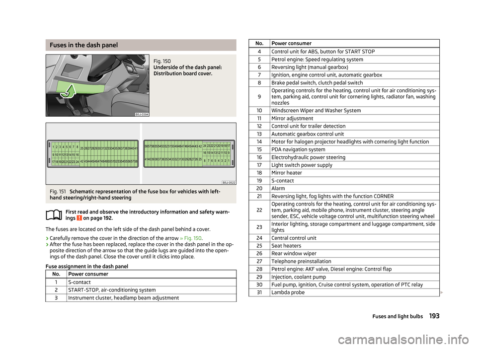
Fuses in the dash panelFig. 150
Underside of the dash panel:
Distribution board cover.
Fig. 151
Schematic representation of the fuse box for vehicles with left-
hand steering/right-hand steering
First read and observe the introductory information and safety warn-
ings
on page 192.
The fuses are located on the left side of the dash panel behind a cover.
› Carefully remove the cover in the direction of the arrow
» Fig. 150.
› After the fuse has been replaced, replace the cover in the dash panel in the op-
posite direction of the arrow so that the guide lugs are guided into the open- ings of the dash panel. Close the cover until it clicks into place.
Fuse assignment in the dash panel
No.Power consumer1S-contact2START-STOP, air-conditioning system3Instrument cluster, headlamp beam adjustmentNo.Power consumer4Control unit for ABS, button for START STOP5Petrol engine: Speed regulating system6Reversing light (manual gearbox)7Ignition, engine control unit, automatic gearbox8Brake pedal switch, clutch pedal switch9Operating controls for the heating, control unit for air conditioning sys-
tem, parking aid, control unit for cornering lights, radiator fan, washing nozzles10Windscreen Wiper and Washer System11Mirror adjustment12Control unit for trailer detection13Automatic gearbox control unit14Motor for halogen projector headlights with cornering light function15PDA navigation system16Electrohydraulic power steering17Light switch power supply18Mirror heater19S-contact20Alarm21Reversing light, fog lights with the function CORNER22Operating controls for the heating, control unit for air conditioning sys-
tem, parking aid, mobile phone, instrument cluster, steering angle
sender, ESC, vehicle voltage control unit, multifunction steering wheel23Interior lighting, storage compartment and luggage compartment, side
lights24Central control unit25Seat heaters26Rear window wiper27Telephone preinstallation28Petrol engine: AKF valve, Diesel engine: Control flap29Injection, coolant pump30Fuel pump, ignition, Cruise control system, operation of PTC relay31Lambda probe 193Fuses and light bulbs
Page 197 of 223
No.Power consumer32High pressure fuel pump, pressure valve33Engine control unit34Engine control unit, vacuum pump35Daytime running lights/radio for vehicles with START-STOP36Main beam37Rear fog light, DC/DC converter START-STOP38Fog lights39Air blower for heating40-41Not assigned42Rear window heater43Horn44Windscreen wipers45Central control unit for convenience system46Engine control unit, fuel pump47Cigarette lighter, power socket in the luggage compartment48ABS, START-STOP (DC/DC) converter ESP49Turn signal lights, brake lights50START-STOP (DC/DC) transformer, radio51Electrical power window (front and rear) - left side52Electrical power window (front and rear) - right side53Parking light = left side, electrical sliding/tilting roof54START-STOP (instrument cluster), alarm55Automatic gearbox control unit56Headlight cleaning system, parking light - right side57Left low beam, headlight range adjustment58Low beam on the right
Fuses in the engine compartmentFig. 152
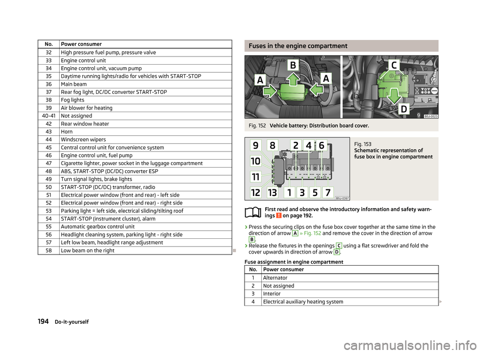
Vehicle battery: Distribution board cover.
Fig. 153
Schematic representation of
fuse box in engine compartment
First read and observe the introductory information and safety warn-
ings on page 192.
› Press the securing clips on the fuse box cover together at the same time in the
direction of arrow
A
» Fig. 152 and remove the cover in the direction of arrow
B
.
› Release the fixtures in the openings
C
using a flat screwdriver and fold the
cover upwards in direction of arrow
D
.
Fuse assignment in engine compartment
No.Power consumer1Alternator2Not assigned3Interior4Electrical auxiliary heating system 194Do-it-yourself
Page 216 of 223
H
Handbrake
99
Hazard warning light system47
Head airbag137
Headlight cleaning system Headlight cleaning system
52
Headlights196
Driving abroad110
Headlight cleaning system52
Head restraint57
Storing in the seat squabs58
Heating Deicing the windows
79
Exterior mirrors53
Operating78
Operation79
Rear window50
Recirculated air mode80
Seats55
Heating and air conditioning77
Hill hold control111
Horn9
I
Ignition
97
Ignition lock97
Immobilizer97
Individual settings locking
32
unlocking32
Inertia reel131
Instrument cluster10
Overview10
Interior monitor36
ISOFIX143
J
Jack
181
Jacking points Raise vehicle
184
Jump-starting187, 188
L
Light Beam adjustment
44
Cockpit48
Headlight flash45
Lights43
Cockpit48, 49
Daylight running44
Fog lights46
Foglights with the CORNER function46
Halogen projector headlights with cornering light
function
45
Hazard warning light system47
Low beam lights43
Main beam lights45
Parking lights43, 47
Rear fog light46
Replacing bulbs195
Switching on and off43
Tourist lights46
Turn signals45
warning lights20
Loads201
Lock Central locking system
33
Locking Emergency locking
31
Remote control34
without central locking30
Locking and unlocking from the inside33
Low beam lights43
Luggage compartment Class N1 vehicles59
Lighting49
Retractable luggage compartment cover (Fabia Estate)
62
Variable loading floor62
M
Main beam
45
Maintenance107
Decorative films153
Manual air conditioning Recirculated air mode
82
Manual gear changing see Gear changing
100
Materials defect liability5
MAXI DOT Main menu
18
see MAXI DOT display18
Settings18
MAXI DOT display18
Maximum speed204
MDI94
Mirror Exterior mirrors
53
Manually dimmed rear-view mirror53
Vanity50
Mobile phone86
Connecting to the hands-free system89
Modes of the automatic transmission101
Modifications147
Modifications and technical changes Service
148
Multifunction display Functions
13
Memory14
Operation14
Multimedia92
213Index