key SKODA FABIA 2013 2.G / 5J Owner's Guide
[x] Cancel search | Manufacturer: SKODA, Model Year: 2013, Model line: FABIA, Model: SKODA FABIA 2013 2.G / 5JPages: 223, PDF Size: 12.77 MB
Page 74 of 223
WARNING■Improper use of the 12-volt power socket and the electrical accessories can
cause fires, burns and other serious injuries.■
Never leave children unattended in the vehicle. The 12-volt power socket
and any connected appliances can also be operated when the ignition is switched off or the ignition key is withdrawn.
■
If the connected electric device becomes too hot, switch it off and discon-
nect it from the power supply immediately.
CAUTION
■ The 12-volt power socket can only be used for connecting approved electrical
accessories with a total power uptake of up to 120 watt.■
Never exceed the maximum power consumption, otherwise the vehicle's elec-
trical system can be damaged.
■
Connecting electrical components when the engine is not running will drain the
battery of the vehicle – there is a risk of the battery discharging.
■
Only use matching plugs to avoid damaging the 12-volt power socket.
■
Only use accessories that have been tested for electromagnetic compatibility in
accordance with the applicable directives.
■
Before turning the ignition on or off, and before starting the car, switch off the
device connected to the 12-volt power socket to prevent any damage caused by
voltage fluctuations.
■
Observe the operating instructions for the connected devices!
Clothes hook
First read and observe the introductory information and safety warn-ings
on page 69.
The clothes hooks are located on the handle of the headliner above each of the
rear doors.
WARNING■ Ensure that any clothes hanging from the hooks do not impair your vision to
the rear.■
Only use the hooks for hanging light items of clothing and ensure that there
are no heavy or sharp-edged objects in the pockets.
■
Do not use clothes hangers for hanging up items of clothing otherwise this
may reduce the effectiveness of head airbags.
CAUTION
The maximum permissible load of the hooks is 2 kg.
Car park ticket holder
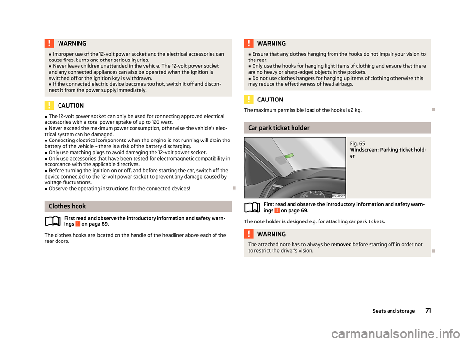
Fig. 65
Windscreen: Parking ticket hold-
er
First read and observe the introductory information and safety warn-
ings on page 69.
The note holder is designed e.g. for attaching car park tickets.
WARNINGThe attached note has to always be removed before starting off in order not
to restrict the driver's vision.
71Seats and storage
Page 93 of 223
Disconnecting the connection
› By withdrawing the ignition key.
› By disconnecting the hands-free system in the mobile phone.
› By disconnecting the user in the
Bluetooth - Users menu item in the MAXI DOT
display.
Solving connection problems
Check the operating status of the mobile phone if the system reports No paired
phone found .
› Is the mobile phone switched on?
› Is the PIN code entered?
› Is Bluetooth ®
active?
› Is the visibility of the mobile phone active?
› Has the mobile phone already been paired with the hands-free system?
Note
■
If a suitable adapter is available for your mobile phone, only use your mobile
phone in the adapter inserted in the telephone mount so that the radiation in the
vehicle drops to a minimum.■
Placing the mobile phone in the adapter inserted in the telephone mount en-
sures optimum sending and receiving power.
Symbols in the MAXI DOT display
First read and observe the introductory information given on page 86.
SymbolMeaningCharge status of the phone battery a)Signal strengtha)a phone is connected to the hands-free system.The hands-free system is visible to other devices.A multimedia unit is connected to the hands-free system.a)
This function is only supported by some mobile phones.
Telephone operation in the MAXI DOT display
First read and observe the introductory information given on page 86.
The following menu items can be selected from the Phone menu.
■ Phone book
■ Dial number 1)
■ Call lists
■ Voice mailbox
■ Bluetooth 1)
■ Settings 2)
■ Back
Phone book
The Phone book menu item lists the contacts downloaded from the telephone
memory and the mobile phone SIM card.
Dial number
Any telephone number can be entered in the Dial number menu item. The re-
quired numbers must be selected one after the other using adjustment wheel
and confirmed by pressing the adjustment wheel. You can select digits 0-9, sym-
bols
,
, , # and the Cancel, Call and Delete functions.
Call lists
The following menu items can be selected in the Call lists menu item.
■ Missed calls
■ Dialled numbers
■ Received calls
Voice mailbox
In the Voice mailbox menu item, you can set the number of the voice mailbox 1)
and then dial the number.
Bluetooth
The following menu items can be selected from the Bluetooth menu item.
■ User - Overview of the stored users
■ New user - Search for new mobile phones in reception range
■ Visibility - Switches on the visibility of the phone for other devices
1)
On vehicles fitted with the Amundsen+ navigation system, this function can be accessed via the navi-
gation system menu; refer to the » Operating instructions for the Amundsen+ navigation system .
2)
This function is not available in vehicles fitted with the Amundsen+ navigation system.
90Using the system
Page 99 of 223
It is still fully possible to steer the vehicle if the power steering fails or if the en-gine is not running (e.g. when towing). However, greater physical effort is re-
quired to turn the steering wheel.
CAUTION
You will place great stresses on the power steering system if the steering is
turned to full lock when the vehicle is stationary. Turning the steering to full lock
in such a situation will be accompanied by noises. Never leave the steering wheel at full lock for more than 15 seconds when the engine is running - there is a risk of
damaging the power steering.
Starting and stopping the engine
Introduction
This chapter contains information on the following subjects:
Electronic immobilizer
97
Ignition lock
97
Starting the engine
97
Switching off the engine
98
The engine can only be started using a correctly coded original key. The engine running noises may louder at first be louder for a short time afterstarting the cold engine. This is quite normal and is not an operating problem.
WARNING■ When the vehicle is travelling with the engine off, the ignition key must al-
ways be in position 2 » Fig. 86 on page 97 (ignition switched on). This posi-
tion is indicated by the warning lights coming on. If this is not the case, it
could result in unexpected locking of the steering wheel – there is the risk of
an accident.■
Only pull the ignition key from the ignition lock when the vehicle has come
to a complete stop (by applying the handbrake). Otherwise the steering wheel
could lock – there is the risk of an accident.
WARNING (Continued)■ When leaving the vehicle, the ignition must always be removed. This is par-
ticularly important if children are left in the vehicle. Otherwise the children
could, for example, start the engine – there is the risk of an accident or injury.■
Never leave the vehicle unattended with the engine running.
■
Never switch off the engine before the vehicle has come to a halt – there is
the risk of an accident.
WARNING■ Never leave the engine running in unventilated or closed rooms. The en-
gine's exhaust gases also contain the odourless and colourless carbon mon-
oxide, a poisonous gas – risk of death. ■ Carbon monoxide can cause unconsciousness and death.
CAUTION
■The starter must only be operated when the engine is not running and the vehi-
cle is at a standstill. The starter or engine can be damaged if the starter is activa-
ted when the engine is running 3
» Fig. 86 on page 97.
■
If the engine does not start up after a second attempt, the fuse for the fuel
pump may have a fault. Check the fuse and replace, if necessary » page 192 or
seek assistance from a specialist garage.
■
Let go of the ignition key as soon as the engine starts otherwise the starter
could be damaged.
■
Do not tow start the engine – there is a risk of damaging the engine and the
catalytic converter. The battery from another vehicle can be used as a jump-start
aid » page 187 , Jump-starting .
CAUTION
■
Avoid high engine speeds, full throttle and high engine loads until the engine
has yet reached its operating temperature – there is a risk of damaging the en-
gine.■
Do not switch the engine off immediately at the end of your journey after the
engine has been operated over a prolonged period at high loads but leave it to
run at an idling speed for about 1 minute. This prevents any possible accumulation
of heat when the engine is switched off.
96Driving
Page 100 of 223
For the sake of the environmentDo not warm up the engine while the vehicle is stationary. If possible, start your
journey as soon as the engine has started. Through this the engine reaches its operating temperature more rapidly and the pollutant emissions are lower.
Note
The radiator fan can intermittently continue to run for approximately 10 minutes
after the ignition has been switched off.
Electronic immobilizer
First read and observe the introductory information and safety warn-ings
on page 96.
An electronic chip is integrated in the head of the key. The immobiliser is deacti-
vated with the aid of this chip when the key is inserted in the ignition lock. The
electronic immobiliser is automatically activated when the ignition key is with-
drawn from the lock.
The engine will not start if a non-authorized ignition key is used. The MAXI DOT display shows the following:
Immobilizer active.
Ignition lock
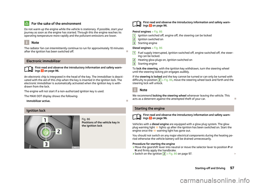
Fig. 86
Positions of the vehicle key in
the ignition lockFirst read and observe the introductory information and safety warn-
ings on page 96.
Petrol engines » Fig. 86
Ignition switched off, engine off, the steering can be locked
Ignition switched on
Starting engine
Diesel engines » Fig. 86
Fuel supply interrupted, ignition switched off, engine switched off, the steer-
ing can be locked.
Heating glow plugs on, ignition switched on
Starting engine
To lock the steering , with the ignition key withdrawn, turn the steering wheel
until the steering locking pin engages audibly.
If the steering is locked and the key cannot be turned or can only be turned with
difficulty to position
2
» Fig. 86 , move the steering wheel back and forth and the
steering lock will unlock.
Note
We recommend locking the steering wheel whenever leaving the vehicle. This
acts as a deterrent against the attempted theft of your car.
Starting the engine
First read and observe the introductory information and safety warn-
ings
on page 96.
Vehicles with a diesel engine are equipped with a glow plug system. The glow
plug warning light
lights up after the ignition has been switched on. Start the
engine once the
warning light has gone out.
You should not switch on any major electrical components during the heating pe- riod otherwise the vehicle battery will be drained unnecessarily.
Procedure for starting the engine
›
Move the gearshift lever into neutral or move the selector lever to position P or
N and firmly apply the handbrake.
›
Switch on the ignition
2
» Fig. 86 on page 97.
12312397Starting-off and Driving
Page 101 of 223
›Depress and hold the clutch pedal (vehicles with a manual gearbox) or brake
pedal (vehicles with an automatic gearbox) until the engine starts.›
Turn the key to position
3
to the stop and release immediately the engine has
started – do not depress the accelerator.
After letting go, the vehicle key will return to position
2
.
›
Release the handbrake.
If the engine does not start within 10 seconds, turn the key to position
1
. Repeat
the start-up process after approx. half a minute.
Switching off the engine
First read and observe the introductory information and safety warn-ings
on page 96.
Switch off the engine by turning the ignition key to position
1
» Fig. 86 on
page 97.
Brakes
Introduction
This chapter contains information on the following subjects:
Information for braking
98
Handbrake
99WARNING■ Greater physical effort is required for braking when the engine is switched
off – there is the risk of an accident.■
The clutch pedal must be depressed when braking on a vehicle with manual
transmission, when the vehicle is in gear and at low revs. If you fail to do so, the functionality of the brake servo can be impaired – there is the risk of an
accident.WARNING (Continued)■ If a front spoiler, full wheel trim, etc. is mounted retrospectively, it must be
ensured that the air supply to the front wheel brakes is not reduced. The front
brakes may overheat, which can have a negative impact on the functioning of
the braking system – there is a risk of an accident.■
Never leave children unattended in the vehicle. The children might, for ex-
ample, release the handbrake or take the vehicle out of gear. The vehicle might then move off – there is the risk of an accident.
CAUTION
■ Observe the recommendations on the new brake pads » page 104.■Never let the brakes slip with light pressure on the pedal if braking is not neces-
sary. This causes the brakes to overheat and can also result in a longer braking distance and excessive wear.
Information for braking
First read and observe the introductory information and safety warn-
ings
on page 98.
If the brakes are applied in full and the control unit for the braking system consid-
ers the situation to be dangerous for the following traffic, the brake light flashes
automatically.
After the speed was reduced below around 10 km/h or the vehicle was stopped,
the brake light stops flashing and the hazard warning light system switches on.
The hazard warning light system is switched off automatically after accelerating
or driving off again.
Before travelling a long distance down a steep gradient, reduce speed and shift
into the next lowest gear. As a result, the braking effect of the engine will be
used, reducing the load on the brakes. Any additional braking should be comple-
ted intermittently, not continuously.
Wear-and-tear
The wear of the brake pads is dependent on the operating conditions and driving style.
The brake pads wear more quickly if a lot of journeys are completed in towns and
over short distances or if a very sporty style of driving is adopted.
98Driving
Page 104 of 223
CAUTION■If the selector lever is shifted to N while the vehicle is being driven you must lift
off the accelerator pedal and you will need to wait until the engine has reached
its idling speed before shifting the selector lever to a forward driving mode again.■
At temperatures below -10 °C, the engine can only be started in selector lever
position P.
■
Never try to hold the vehicle using the accelerator pedal when stopping on a hill
– this may lead to transmission damage.
Note
The ignition key can only be withdrawn once the ignition has been switched off if
the selector lever is in the P position 1)
.
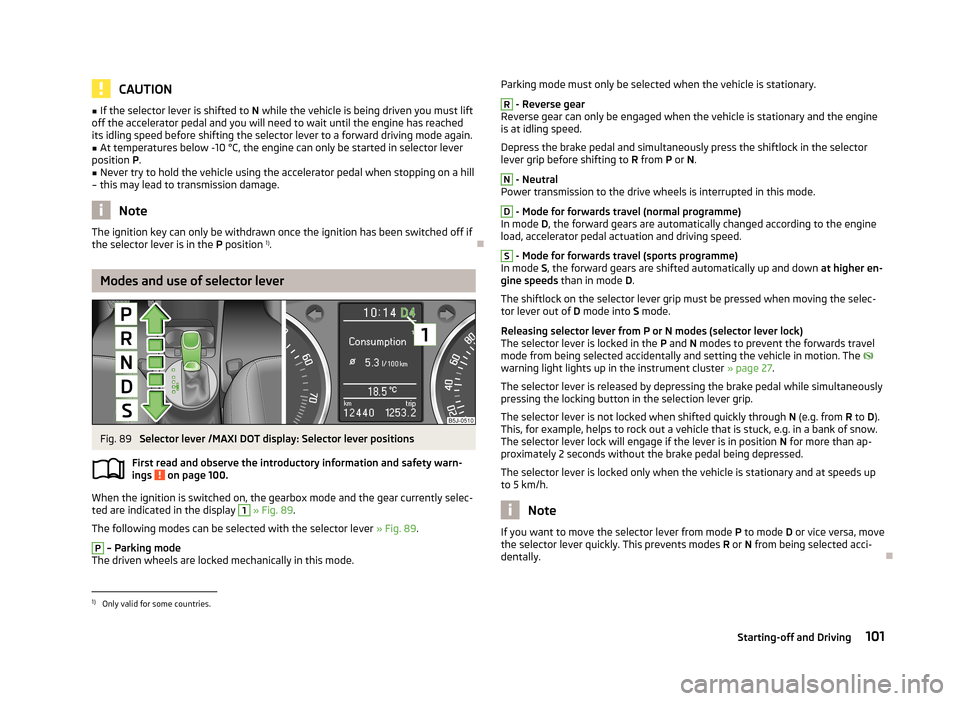
Modes and use of selector lever
Fig. 89
Selector lever /MAXI DOT display: Selector lever positions
First read and observe the introductory information and safety warn-
ings
on page 100.
When the ignition is switched on, the gearbox mode and the gear currently selec-
ted are indicated in the display
1
» Fig. 89 .
The following modes can be selected with the selector lever » Fig. 89.
P
– Parking mode
The driven wheels are locked mechanically in this mode.
Parking mode must only be selected when the vehicle is stationary.R
- Reverse gear
Reverse gear can only be engaged when the vehicle is stationary and the engine
is at idling speed.
Depress the brake pedal and simultaneously press the shiftlock in the selector
lever grip before shifting to R from P or N.
N
- Neutral
Power transmission to the drive wheels is interrupted in this mode.
D
- Mode for forwards travel (normal programme)
In mode D, the forward gears are automatically changed according to the engine
load, accelerator pedal actuation and driving speed.
S
- Mode for forwards travel (sports programme)
In mode S, the forward gears are shifted automatically up and down at higher en-
gine speeds than in mode D.
The shiftlock on the selector lever grip must be pressed when moving the selec-
tor lever out of D mode into S mode.
Releasing selector lever from P or N modes (selector lever lock) The selector lever is locked in the P and N modes to prevent the forwards travel
mode from being selected accidentally and setting the vehicle in motion. The
warning light lights up in the instrument cluster » page 27.
The selector lever is released by depressing the brake pedal while simultaneously
pressing the locking button in the selection lever grip.
The selector lever is not locked when shifted quickly through N (e.g. from R to D).
This, for example, helps to rock out a vehicle that is stuck, e.g. in a bank of snow.
The selector lever lock will engage if the lever is in position N for more than ap-
proximately 2 seconds without the brake pedal being depressed.
The selector lever is locked only when the vehicle is stationary and at speeds up to 5 km/h.
Note
If you want to move the selector lever from mode P
to mode D or vice versa, move
the selector lever quickly. This prevents modes R or N from being selected acci-
dentally.1)
Only valid for some countries.
101Starting-off and Driving
Page 122 of 223
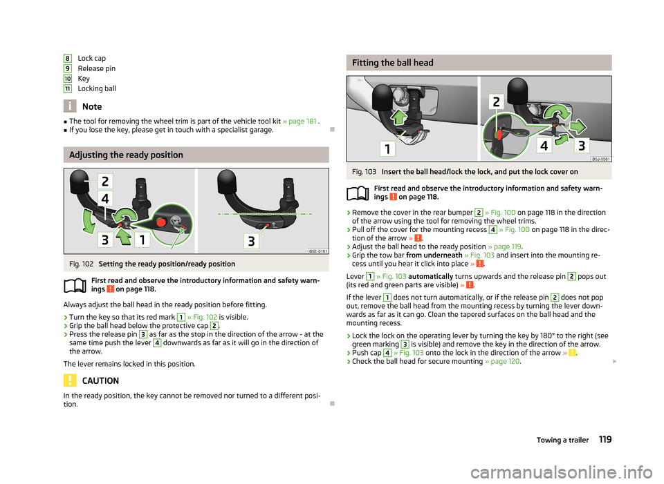
Lock cap
Release pin
Key
Locking ball
Note
■ The tool for removing the wheel trim is part of the vehicle tool kit » page 181 .■If you lose the key, please get in touch with a specialist garage.
Adjusting the ready position
Fig. 102
Setting the ready position/ready position
First read and observe the introductory information and safety warn- ings
on page 118.
Always adjust the ball head in the ready position before fitting.
›
Turn the key so that its red mark
1
» Fig. 102 is visible.
›
Grip the ball head below the protective cap
2
.
›
Press the release pin
3
as far as the stop in the direction of the arrow - at the
same time push the lever
4
downwards as far as it will go in the direction of
the arrow.
The lever remains locked in this position.
CAUTION
In the ready position, the key cannot be removed nor turned to a different posi-
tion.891011
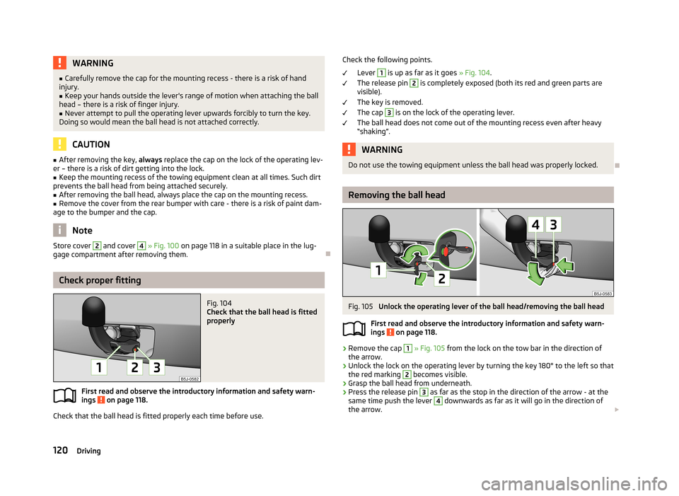
Fitting the ball headFig. 103
Insert the ball head/lock the lock, and put the lock cover on
First read and observe the introductory information and safety warn-
ings
on page 118.
›
Remove the cover in the rear bumper
2
» Fig. 100 on page 118 in the direction
of the arrow using the tool for removing the wheel trims.
›
Pull off the cover for the mounting recess
4
» Fig. 100 on page 118 in the direc-
tion of the arrow » .
›
Adjust the ball head to the ready position » page 119.
›
Grip the tow bar from underneath » Fig. 103 and insert into the mounting re-
cess until you hear it click into place » .
Lever
1
» Fig. 103 automatically turns upwards and the release pin
2
pops out
(its red and green parts are visible) » .
If the lever
1
does not turn automatically, or if the release pin
2
does not pop
out, remove the ball head from the mounting recess by turning the lever down-
wards as far as it can go. Clean the tapered surfaces on the ball head and the
mounting recess.
›
Lock the lock on the operating lever by turning the key by 180° to the right (see
green marking
3
is visible) and remove the key in the direction of the arrow.
›
Push cap
4
» Fig. 103 onto the lock in the direction of the arrow » .
›
Check the ball head for secure mounting » page 120.
119Towing a trailer
Page 123 of 223
WARNING■Carefully remove the cap for the mounting recess - there is a risk of hand
injury.■
Keep your hands outside the lever's range of motion when attaching the ball
head – there is a risk of finger injury.
■
Never attempt to pull the operating lever upwards forcibly to turn the key.
Doing so would mean the ball head is not attached correctly.
CAUTION
■ After removing the key, always replace the cap on the lock of the operating lev-
er – there is a risk of dirt getting into the lock.■
Keep the mounting recess of the towing equipment clean at all times. Such dirt
prevents the ball head from being attached securely.
■
After removing the ball head, always place the cap on the mounting recess.
■
Remove the cover from the rear bumper with care - there is a risk of paint dam-
age to the bumper and the cap.
Note
Store cover 2 and cover 4 » Fig. 100 on page 118 in a suitable place in the lug-
gage compartment after removing them.
Check proper fitting
Fig. 104
Check that the ball head is fitted
properly
First read and observe the introductory information and safety warn-
ings on page 118.
Check that the ball head is fitted properly each time before use.
Check the following points.
Lever 1
is up as far as it goes » Fig. 104.
The release pin
2
is completely exposed (both its red and green parts are
visible).
The key is removed.
The cap
3
is on the lock of the operating lever.
The ball head does not come out of the mounting recess even after heavy
“shaking”.
WARNINGDo not use the towing equipment unless the ball head was properly locked.
Removing the ball head
Fig. 105
Unlock the operating lever of the ball head/removing the ball head
First read and observe the introductory information and safety warn- ings
on page 118.
›
Remove the cap
1
» Fig. 105 from the lock on the tow bar in the direction of
the arrow.
›
Unlock the lock on the operating lever by turning the key 180° to the left so that
the red marking
2
becomes visible.
›
Grasp the ball head from underneath.
›
Press the release pin
3
as far as the stop in the direction of the arrow - at the
same time push the lever
4
downwards as far as it will go in the direction of
the arrow.
120Driving
Page 124 of 223
The ball head is released in this position and falls freely into the hand. If it does
not fall freely into the hand, use your other hand to push it upwards.
At the same time, the ball head latches into the ready position and is thus readyto be re-inserted into the mounting recess »
.
›
Fit the cover for the mounting recess
4
» Fig. 100 on page 118 in the opposite
direction to the arrow.
›
Offer up the cap to the rear bumper
2
» Fig. 100 on page 118 aligning it with
“check mark” in the lower bumper area.
›
Push the cap in first on the left and right and then at the top.
WARNINGNever allow the ball head to remain unsecured in the boot. This could cause damage in a sudden braking manoeuvre and put the safety of the occupantsat risk.
CAUTION
■ If the lever is held firm and not pushed downwards as far as it can go, it will go
back up after the ball head is removed and will not latch into the ready position.
The ball head then needs to be brought into this position before the next time it
is fitted.■
Stow the ball head in the ready position with the key inserted in the box. When
doing so, make the side opposite to the inserted key face downwards – there is a
risk of damaging the key.
■
Do not use excessive force when handling the operating lever (e.g. do not step
on it).
Note
■ We recommend that you put the protective cap on the ball before removing the
ball head.■
Clean any dirt from the ball head before stowing it away in the box with the ve-
hicle tool kit.
Use and care
First read and observe the introductory information and safety warn-
ings
on page 118.
Close the mounting recess with the cap to prevent any ingress of dirt.
Always check the ball head before hitching a trailer. Apply a suitable grease where necessary.
Fit the protective cap when stowing away the ball head to protect the luggage
compartment against dirt.
In the event of dirt, clean the surfaces of the mounting recess and treat with a
suitable preservative.
CAUTION
Apply grease to the upper part of the mounting recess. Make sure you do not re-
move any grease.
Trailer
Introduction
This chapter contains information on the following subjects:
Loading a trailer
121
Towing a trailer
122
Anti-theft alarm system
123WARNINGAlways drive particularly carefully with the trailer.
Loading a trailer
First read and observe the introductory information and safety warn-
ings
on page 121.
The vehicle/trailer combination must be balanced, whereby the maximum permis-
sible drawbar load must be utilised. If the drawbar load is too low, it jeopardises the performance of the vehicle/trailer combination.
Distribution of the load
Distribute the load in the trailer in such a way that heavy items are located as close to the axle as possible. Secure the items from slipping.
121Towing a trailer
Page 126 of 223
Note■After coupling the trailer and connecting up the power socket, check the rear
lights on the trailer to ensure they work.■
If there is an error in the trailer lighting system, check the fuses in the fuse box
in the dashboard » page 193.
■
If you tow a trailer frequently, you should also have your car inspected between
service intervals.
■
The handbrake on the towing vehicle must be applied when coupling and un-
coupling the trailer.
Anti-theft alarm system
First read and observe the introductory information and safety warn-
ings
on page 121.
When the vehicle is locked, the alarm is activated as soon as the electrical con- nection to the trailer is interrupted.
Always switch off the anti-theft alarm system before a trailer is coupled or uncou- pled » page 35 .
Conditions for including a trailer in the anti-theft alarm system. The vehicle is factory-fitted with an anti-theft alarm system and towingequipment.
The trailer is electrically connected to the towing vehicle by means of the
trailer socket.
The electrical system of the vehicle and trailer is functional. The vehicle is locked with the vehicle key and the anti-theft alarm system isactivated.
Note
For technical reasons, trailers with rear LED lights cannot be connected to the an-
ti-theft alarm system.
123Towing a trailer