dashboard warning lights SKODA FABIA 2014 2.G / 5J Owner's Manual
[x] Cancel search | Manufacturer: SKODA, Model Year: 2014, Model line: FABIA, Model: SKODA FABIA 2014 2.G / 5JPages: 197, PDF Size: 13.56 MB
Page 27 of 197
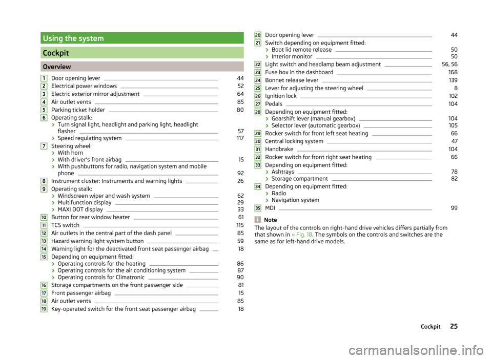
Using the system
Cockpit
OverviewDoor opening lever
44
Electrical power windows
52
Electric exterior mirror adjustment
64
Air outlet vents
85
Parking ticket holder
80
Operating stalk:
› Turn signal light, headlight and parking light, headlight
flasher
57
› Speed regulating system
117
Steering wheel:
› With horn
› With driver’s front airbag
15
›With pushbuttons for radio, navigation system and mobile
phone
92
Instrument cluster: Instruments and warning lights
26
Operating stalk:
› Windscreen wiper and wash system
62
›Multifunction display
29
›MAXI DOT display
33
Button for rear window heater
61
TCS switch
115
Air outlets in the central part of the dash panel
85
Hazard warning light system button
59
Warning light for the deactivated front seat passenger airbag
18
Depending on equipment fitted:
› Operating controls for the heating
86
›Operating controls for the air conditioning system
87
›Operating controls for Climatronic
90
Storage compartments on the front passenger side
81
Front passenger airbag
15
Air outlet vents
85
Key-operated switch for the front seat passenger airbag
1812345678910111213141516171819Door opening lever44
Switch depending on equipment fitted:
› Boot lid remote release
50
›Interior monitor
50
Light switch and headlamp beam adjustment
56, 56
Fuse box in the dashboard
168
Bonnet release lever
139
Lever for adjusting the steering wheel
8
Ignition lock
102
Pedals
104
Depending on equipment fitted:
› Gearshift lever (manual gearbox)
104
›Selector lever (automatic gearbox)
105
Rocker switch for front left seat heating
66
Central locking system
47
Handbrake
104
Rocker switch for front right seat heating
66
Depending on equipment fitted:
› Ashtrays
78
›Storage compartment
82
Depending on equipment fitted:
› Radio
› Navigation system
MDI
99
Note
The layout of the controls on right-hand drive vehicles differs partially from
that shown in » Fig. 18. The symbols on the controls and switches are the
same as for left-hand drive models.2021222324252627282930313233343525Cockpit
Page 127 of 197
On downhill sections shift down a gear in good time to also use the engine as
a brake.
Engine overheating
The speed must be reduced immediately if the needle for the coolant tempera-
ture gauge moves into the right-hand area or the red area of the scale.
Stop and switch off the engine if the warning light
in the instrument cluster
starts to flash. Wait a few minutes and check the level of coolant » page 144,
Checking the coolant level .
The following guidelines must be observed » page 37,
Coolant .
The coolant temperature can be reduced by switching on the heating.WARNING■ Adapt your speed to the conditions of the road surface and to the traffic
situation.■
Improper or incorrectly connected electric cables can energise the trailer
and cause functional faults to the vehicle's entire electrical system as well
as accidents and severe injuries.
■
Work on the electrical system must only be carried out by specialist ga-
rages.
■
Never directly connect the trailer's electrical system with the electrical
connections for the tail lights or other current sources.
Note
■ After coupling the trailer and connecting up the power socket, check the rear
lights on the trailer to ensure they work.■
If there is an error in the trailer lighting system, check the fuses in the fuse
box in the dashboard » page 168.
■
If you tow a trailer frequently, you should also have your car inspected be-
tween service intervals.
■
The handbrake on the towing vehicle must be applied when coupling and un-
coupling the trailer.
Anti-theft alarm system
Read and observe
on page 124 first.
When the vehicle is locked, the alarm is activated as soon as the electrical con-
nection to the trailer is interrupted.
Always switch off the anti-theft alarm system before a trailer is coupled or un-
coupled » page 49 .
Conditions for including a trailer in the anti-theft alarm system. The vehicle is factory-fitted with an anti-theft alarm system and towing
equipment.
The trailer is electrically connected to the towing vehicle by means of the
trailer socket.
The electrical system of the vehicle and trailer is functional.
The vehicle is locked with the vehicle key and the anti-theft alarm system is activated.
Note
For technical reasons, trailers with rear LED lights cannot be connected to the
anti-theft alarm system.125Towing a trailer
Page 165 of 197
WARNING■A tyre filled with sealant has the same driving characteristics as a stand-
ard tyre.■
Do not travel faster than 80 km/h.
■
Avoid accelerating at full throttle, sharp braking and fast cornering.
■
Check the tyre pressure after driving for 10 minutes.
■
The sealant is hazardous to heath. Remove immediately if it comes into
contact with the skin.
For the sake of the environment
Used sealant or sealant whose expiry date has passed must be disposed of in
accordance with environmental protection regulations.
Note
■ Observe the manufacturer's usage instructions for the breakdown kit.■A new bottle of sealant can be purchased from ŠKODA Original Parts.■
Immediately replace the wheel that was repaired using the breakdown kit or
consult a specialist garage about repair possibilities.
Breakdown kit
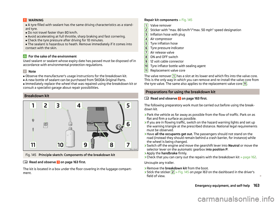
Fig. 145
Principle sketch: Components of the breakdown kit
Read and observe
on page 163 first.
The kit is located in a box under the floor covering in the luggage compart-
ment.
Repair kit components » Fig. 145
Valve remover
Sticker with “max. 80 km/h”/“max. 50 mph” speed designation
Inflation hose with plug
Air compressor
Tyre inflation hose
Tyre pressure indicator
Air release valve
ON and OFF switch
12 volt cable connector
Tyre inflator bottle with sealing agent
Replacement valve core
The valve remover 1
has a slot at its lower end which fits into the valve core.
This is the only way in which you can remove and re-install the valve core from
the tyre valve. The same also applies to the replacement valve core
11
.
Preparations for using the breakdown kit
Read and observe
on page 163 first.
The following preparatory work must be carried out before using the break-
down kit.
›
Park the vehicle as far away as possible from the flow of traffic. Park on as
flat and firm a surface as possible.
›
If you are in flowing traffic, switch on the hazard warning lights and set up
the warning triangle at the prescribed distance. National legal requirements
must be observed.
›
Have all the occupants get out. The passengers should not stand on the
road (instead they should remain behind a crash barrier, for instance) while
the wheel is being changed.
›
Switch off the engine and move the gearshift lever into Neutral or move the
selector lever on the automatic gearbox into position P.
›
Apply the handbrake firmly.
›
Check that you can carry out the repairs with the breakdown kit » page 162.
Uncouple any trailer.
›
Remove the breakdown kit from the boot.
›
Stick the sticker
2
» Fig. 145 on page 163 on the dashboard in the driver's
field of view.
1234567891011163Emergency equipment, and self-help