set clock SKODA FABIA 2014 2.G / 5J Owner's Manual
[x] Cancel search | Manufacturer: SKODA, Model Year: 2014, Model line: FABIA, Model: SKODA FABIA 2014 2.G / 5JPages: 197, PDF Size: 13.56 MB
Page 10 of 197
WARNING■Always assume the correct seated position before setting off and do not
change this position while driving. Also advise your passengers to adopt
the correct seated position and not to change this position while the car is
moving.■
Maintain a distance of at least 25 cm from the steering wheel, and a dis-
tance of at least 10 cm between the legs and the dash panel at the height
of the knee airbag. Not maintaining this minimum distance will mean that
the airbag system will not be able to properly protect you - hazard!
■
When driving, hold the steering wheel with both hands firmly on the out-
er edge in the “9 o'clock” and “3 o'clock” position. Never hold the steering
wheel in the “12 o'clock” position or in any other way (e.g. in the middle or
inner edge of the steering wheel). In such cases, you could severely injure
your arms, hands and head when the driver airbag is deployed.
■
Ensure that there are no objects in the driver's footwell, as these may get
caught in the pedal apparatus when driving or braking. You would then no
longer be able to operate the clutch, brake or acceleration pedals.
Adjusting the steering wheel position
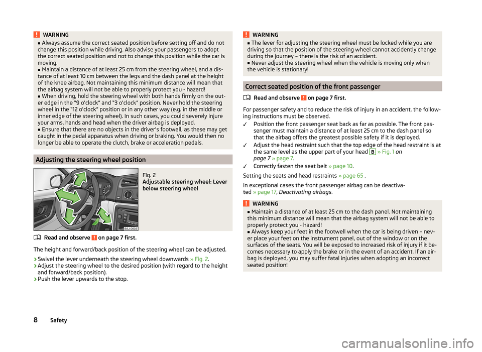
Fig. 2
Adjustable steering wheel: Lever
below steering wheel
Read and observe on page 7 first.
The height and forward/back position of the steering wheel can be adjusted.
›
Swivel the lever underneath the steering wheel downwards » Fig. 2.
›
Adjust the steering wheel to the desired position (with regard to the height
and forward/back position).
›
Push the lever upwards to the stop.
WARNING■ The lever for adjusting the steering wheel must be locked while you are
driving so that the position of the steering wheel cannot accidently change
during the journey – there is the risk of an accident.■
Never adjust the steering wheel when the vehicle is moving only when
the vehicle is stationary!
Correct seated position of the front passenger
Read and observe
on page 7 first.
For passenger safety and to reduce the risk of injury in an accident, the follow-ing instructions must be observed.
Position the front passenger seat back as far as possible. The front pas-
senger must maintain a distance of at least 25 cm to the dash panel so
that the airbag offers the greatest possible safety if it is deployed.
Adjust the head restraint such that the top edge of the head restraint is at
the same level as the upper part of your head
B
» Fig. 1 on
page 7 » page 7 .
Correctly fasten the seat belt » page 10.
Setting the seats and head restraints » page 65 .
In exceptional cases the front passenger airbag can be deactiva-
ted » page 17 , Deactivating airbags .
WARNING■
Maintain a distance of at least 25 cm to the dash panel. Not maintaining
this minimum distance will mean that the airbag system will not be able to
properly protect you - hazard!■
Always keep your feet in the footwell when the car is being driven – nev-
er place your feet on the instrument panel, out of the window or on the
surfaces of the seats. You will be exposed to increased risk of injury if it be-
comes necessary to apply the brake or in the event of an accident. If an air-
bag is deployed, you may suffer fatal injuries when adopting an incorrect
seated position!
8Safety
Page 28 of 197
Instruments and Indicator Lights
Instrument cluster
Introduction
This chapter contains information on the following subjects:
Overview
26
Engine revolutions counter
27
Speedometer
27
Coolant temperature gauge display
27
Fuel gauge
27
Counter for distance driven
28
Digital clock
28
Display of the second speed
28
Recommended gear
28
Fault display
The Error message will appear in the display if there is a fault in the instru-
ment cluster. Ensure that the fault is rectified as soon as possible by a special-
ist workshop.
WARNING■ Concentrate fully at all times on your driving! As the driver you are fully
responsible for road safety.■
Never operate the controls in the instrument cluster while driving, only
when the vehicle is stationary!
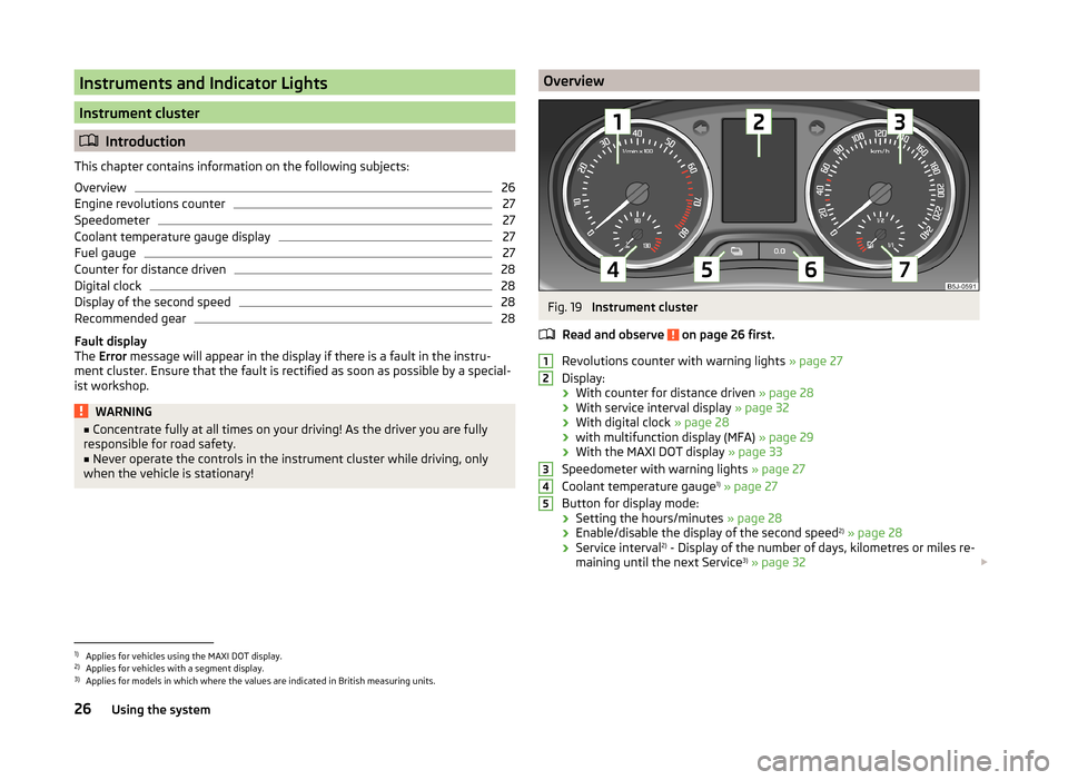
OverviewFig. 19
Instrument cluster
Read and observe
on page 26 first.
Revolutions counter with warning lights » page 27
Display:
› With counter for distance driven
» page 28
› With service interval display
» page 32
› With digital clock
» page 28
› with multifunction display (MFA)
» page 29
› With the MAXI DOT display
» page 33
Speedometer with warning lights » page 27
Coolant temperature gauge 1)
» page 27
Button for display mode:
› Setting the hours/minutes
» page 28
› Enable/disable the display of the second speed 2)
» page 28
› Service interval 2)
- Display of the number of days, kilometres or miles re-
maining until the next Service 3)
» page 32
123451)
Applies for vehicles using the MAXI DOT display.
2)
Applies for vehicles with a segment display.
3)
Applies for models in which where the values are indicated in British measuring units.
26Using the system
Page 30 of 197
CAUTIONNever drive until the fuel tank is completely empty! The irregular supply of fuel
can cause misfiring. This can result in considerable damage to parts of the en-
gine and the exhaust system.
Counter for distance driven
Read and observe
on page 26 first.
The distance which you have driven with your vehicle is shown in km. In some
countries the measuring unit “mile” is used.
Daily trip counter (trip)
The trip counter indicates the distance you have driven since it was last reset -
in steps of 100 metres or 1/10 of a mile.
Reset trip meter
The meter can be reset by pressing and holding button
6
» Fig. 19 on page 26 .
Odometer
The odometer indicates the total distance in kilometres or miles which the ve-
hicle has been driven.
Note
If the second speed display is enabled on vehicles with a segment display, this
speed will be shown instead of the odometer.
Digital clock
Read and observe
on page 26 first.
The clock is set with buttons
5
and
6
» Fig. 19 on page 26 .
Select the display that you wish to change with the button
5
and carry out
the change with the button
6
.
In vehicles equipped with the MAXI DOT display, it is also possible to set the
clock in the Time menu » page 34.
Display of the second speed
Read and observe
on page 26 first.
The display can show the current speed in mph 1)
.
This feature is provided for driving in countries with different units for speed.
MAXI DOT display
The display of the second speed can be set in the Settings menu
item » page 34 , Settings .
Segment display
›
Press the
5
» Fig. 19 on page 26 key repeatedly, until the odometer display
flashes » page 28 .
›
Press the
6
key while the display is flashing.
The second speed is displayed instead of the odometer.
Display of the second speed can be disabled in the same way.
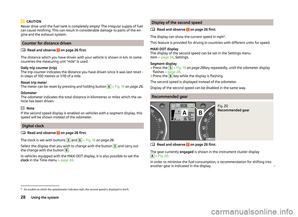
Recommended gear
Fig. 20
Recommended gear
Read and observe on page 26 first.
The gear currently engaged is shown in the instrument cluster display
A
» Fig. 20 .
In order to minimise the fuel consumption, a recommendation for shifting into
another gear is indicated in the display.
1)
On models on which the speedometer indicates mph, the second speed is displayed in km/h.
28Using the system
Page 150 of 197
We therefore recommend that you have the battery checked and, if necessary,
recharged by a specialist garage before the start of the winter.
CAUTION
For technical reasons, on vehicles with the description “AGM”, the electrolyte
level cannot be checked.
Note
The battery electrolyte level is also periodically checked by a specialist garage
as part of the Inspection Service.
Charging
Read and observe
and on page 146 first.
A properly charged vehicle battery is essential for reliably starting the engine.
›
Switch off the ignition and all of the electrical components.
›
Only when performing a “quick-charge”, disconnect both battery cables (first
“negative”, then “positive”).
›
Attach the terminal clamps of the charger to the battery terminals (red =
“positive”, black = “negative”).
›
Plug the mains cable of the charger into the power socket and switch the
charger on.
›
Once charging is complete: Switch off the charger and remove the mains ca-
ble from the power socket.
›
Only then disconnect the charger's terminal clamps.
›
Reconnect the cables to the battery (first “positive”, then “negative”).
It is not necessary to disconnect the battery cables if you are recharging the
vehicle battery using low amperages (for example from a mini-charger). Refer
to the charger manufacturer's instructions .
A charging current of 0.1 multiple of the total vehicle battery capacity (or low-
er) must be used until full charging is achieved.
Both cables must be disconnected before charging the battery with high
amperages, known as “ rapid charging”.
The vent plugs of the vehicle battery should not be opened for charging.
WARNING“Quick-charging” the vehicle battery is dangerous and requires a special
charger and specialist knowledge.CAUTIONOn vehicles with the START/STOP system, the pole terminal of the charger
must not be connected directly to the negative terminal of the vehicle battery,
but only to the engine earth » page 166, Jump-starting in vehicles with the
START-STOP system .
Note
We therefore recommend that vehicle batteries be rapid charged by a special-
ist garage.
Replacing
Read and observe
and on page 146 first.
The new vehicle battery must have the same capacity, voltage, current and thesame size as the original battery. Suitable vehicle battery types can be pur-
chased from a specialist garage.
We recommend that the battery is replaced by a specialist garage, where the
new vehicle battery will be installed properly and the original battery will be
disposed of in accordance with national regulations.
Disconnecting or reconnecting
Read and observe
and on page 146 first.
The following functions are initially deactivated or are no longer able to oper-
ate faultlessly after the vehicle battery has been disconnected and reconnec-
ted.
OperationOperating measureElectrical power window (operational faults)» page 53Enter the radio/navigation system code
number» User manual of the radio
or » user manual of the naviga-
tion systemSetting the clock» page 28Data in the multifunction display are de-
leted.» page 29
Note
We recommend having the vehicle checked by a specialist garage to ensure
the full functionality of all electrical systems.148General Maintenance
Page 157 of 197
WARNING■When the warning light illuminates, immediately reduce the speed and
avoid sudden steering and brake manoeuvres. Stop the vehicle as soon as
possible and inspect the tyres and their inflation pressure.■
Under certain circumstances (e.g. sporty style of driving, wintry or un-
paved roads) the warning light
can be delayed or does not light up at all.
CAUTION
■
The system cannot warn in case of very rapid loss of tyre pressure, e.g. in the
event of a sudden puncture. In this case carefully bring the vehicle to a stand-
still without sudden steering movements or sharp braking.■
The basic setting must be repeated every 10,000 km or once a year to ensure
proper functioning of the tyre pressure monitor.
■
The tyre pressure monitor does not replace the need to check tyre pressure
regularly.
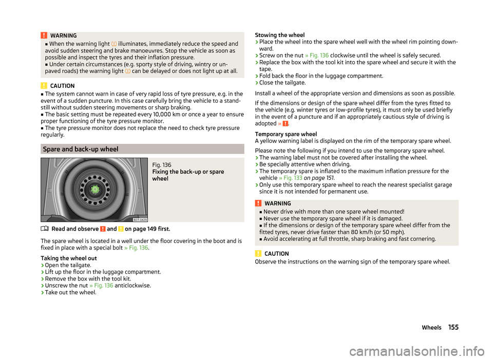
Spare and back-up wheel
Fig. 136
Fixing the back-up or spare
wheel
Read and observe and on page 149 first.
The spare wheel is located in a well under the floor covering in the boot and is fixed in place with a special bolt » Fig. 136.
Taking the wheel out
›
Open the tailgate.
›
Lift up the floor in the luggage compartment.
›
Remove the box with the tool kit.
›
Unscrew the nut » Fig. 136 anticlockwise.
›
Take out the wheel.
Stowing the wheel›Place the wheel into the spare wheel well with the wheel rim pointing down-
ward.›
Screw on the nut » Fig. 136 clockwise until the wheel is safely secured.
›
Replace the box with the tool kit into the spare wheel and secure it with the
tape.
›
Fold back the floor in the luggage compartment.
›
Close the tailgate.
Install a wheel of the appropriate version and dimensions as soon as possible.
If the dimensions or design of the spare wheel differ from the tyres fitted to
the vehicle (e.g. winter tyres or low-profile tyres), it must only be used briefly
in the event of a puncture and if an appropriately cautious style of driving is
adopted »
.
Temporary spare wheel
A yellow warning label is displayed on the rim of the temporary spare wheel.
Please note the following if you intend to use the temporary spare wheel. › The warning label must not be covered after installing the wheel.
› Be specially attentive when driving.
› The temporary spare is inflated to the maximum inflation pressure for the
vehicle » Fig. 133 on page 151 .
› Only use this temporary spare wheel to reach the nearest specialist garage
since it is not intended for permanent use.
WARNING■ Never drive with more than one spare wheel mounted!■Never use the temporary spare wheel if it is damaged.■
If the dimensions or design of the temporary spare wheel differ from the
fitted tyres, never drive faster than 80 km/h (or 50 mph).
■
Avoid accelerating at full throttle, sharp braking and fast cornering.
CAUTION
Observe the instructions on the warning sign of the temporary spare wheel.155Wheels
Page 188 of 197

BulbsChanging170
In the rear light174
Button in the driver's door Electrical power windows
51
C
Car care
126
Jack132
Washing128
Car computer see Multifunction display
29
Caring for paintwork130
Car park ticket holder80
Carrier76
Central locking button47
Central locking system45
lock47
unlock47
Changing Brake fluid
145
Bulbs170
Bulbs in the rear light174
Engine oil143
Foglight bulb (Scout, RS)173
Foglights and daytime running lights bulbs173
Front parking light bulb172
Front turn signal bulb172
Fuses168
Fuses in the dash panel168
Fuses in the engine compartment170
High beam bulb - halogen projector headlights 172
Licence plate light bulb
174
Low beam and high beam bulb - halogen head- lights
171
Low beam and high beam bulb - halogen pro- jector headlights
172
Wheels159
Changing a wheel Preparation160
Removing and fitting a wheel160
Subsequent steps160
Charging a vehicle battery148
Check Fit ball head properly
122
Checking Battery electrolyte level
147
Brake fluid145
Coolant level144
Engine oil142
Oil level142
Windscreen washer fluid140
Children and safety19
Child safety Side airbag
21
Child safety lock44
Child safety seat Use of child safety seats
21
Child seat Classification
21
ISOFIX22
on the front passenger seat20
TOP TETHER23
Use of ISOFIX child seats22
Chrome parts refer to Taking care of your vehicle
130
Cigarette lighter79
Cleaning126
Alcantara134
Covers on electrically heated seats134
Fabrics134
Headlight lenses131
Natural leather133
Plastic parts130
Synthetic leather134
Wheels132
Climatronic90
Automatic mode91
Control elements90
Controlling the blower91
Defrosting windscreen92
Recirculated air mode91
Setting the temperature91
Clock28
Clothes hook80
Cockpit 12-volt power outlet
79
Ashtray78
Cigarette lighter79
General view25
Lighting59
Storage compartments80
Compartments80
Computer see Multifunction display
29
Convenience turn signal57
Coolant143
Checking144
Display messages37
Replenishing144
Warning light37
Coolant temperature gauge display
27
Correct seated position7
Driver7
Front passenger8
Notes9
Rear seats9
Counter for distance driven28
Cruise control system117
Cupholders78
D
DAY LIGHT see Daylight running lights
56
Daylight running lights56
186Index
Page 192 of 197

SeatAdjusting65
Seat belt warning light
36
Seat belts10
Belt tensioners13
Cleaning134
fastening and unfastening12
Height adjustment13
Seatbelts Inertia reels
13
Seat belts The physical principle of a frontal collision
11
Seats folding forward
66
Head restraints68
Heating66
Removing the seats67
Seats and storage65
see Automatic gearbox Manual gear shifting on the multifunction steering wheel
106
Selector lever see Using the selector lever
105
Service display32
Service intervals126
Setting Heating
87
Manual air conditioning system89
Manually dimmed rear-view mirror64
Setting the clock Clock
28
Shifting gears Driving and saving energy
109
Side airbag16
Sliding/tilting roof53
Comfort operation54
Emergency operation55
Opening and raising54
Operation54
Sliding/tilting sunroof Closing54
Snow chains157
Spare wheel155
Speedometer27
Speed symbol see Wheels
152
Spoiler127
Stalk Main beam
57
Turn signals57
START-STOP118
Operating conditions for the system118
operation119
system-related automatic start-up119
START-STOPP Manually deactivating/activating the system
119
Starting and stopping the engine101
Starting engine Jump-starting
164
Starting the engine102
Jump-starting165
START STOP Information messages
119
Jump-starting166
Steering wheel8
Storage80
Storage Compartment Lighting
60
Storage compartments80
Sun visors61
Switching lights on and off56
Switching off the engine102
Synthetic leather134
T
Tailgate
50
Taking care of the vehicle Natural leather133
Seat belts134
Taking care of your vehicle Automatic car wash system
129
Chrome parts130
Cleaning the wheels132
Door lock cylinders131
Headlight lenses131
High-pressure cleaner129
Plastic parts130
Washing by hand128
Wash system129
Technical data176
Telephone92
Tiptronic106
Tire Explanation of the labelling
152
see wheels152
Tire size152
see wheels152
Tools159
TOP TETHER23
Tourist lights58
Towing166
Towing a trailer120
Towing device Description
121
Drawbar load120
Use and care123
Towing eye Front
167
Rear167
Towing protection50
Traction Control System (ASR)115
Trailer120, 124
Loading124
Towing a trailer124
190Index