air condition SKODA FABIA 2015 3.G / NJ User Guide
[x] Cancel search | Manufacturer: SKODA, Model Year: 2015, Model line: FABIA, Model: SKODA FABIA 2015 3.G / NJPages: 220, PDF Size: 32.46 MB
Page 99 of 220
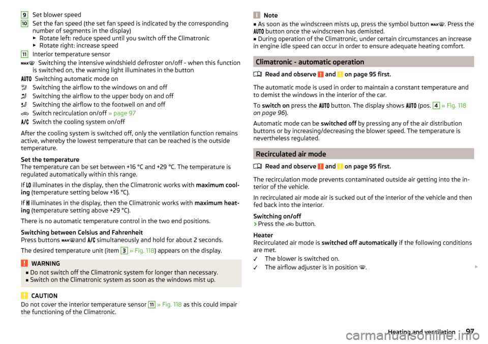
Set blower speed
Set the fan speed (the set fan speed is indicated by the corresponding
number of segments in the display)
▶ Rotate left: reduce speed until you switch off the Climatronic
▶ Rotate right: increase speed
Interior temperature sensor Switching the intensive windshield defroster on/off - when this function
is switched on, the warning light illuminates in the button
Switching automatic mode on
Switching the airflow to the windows on and off
Switching the airflow to the upper body on and off
Switching the airflow to the footwell on and off
Switch recirculation on/off » page 97
Switch the cooling system on/off
After the cooling system is switched off, only the ventilation function remains active, whereby the lowest temperature that can be reached is the outside
temperature.
Set the temperature
The temperature can be set between +16 °C and +29 °C. The temperature is
regulated automatically within this range.
If illuminates in the display, then the Climatronic works with
maximum cool-
ing (temperature setting below +16 °C).
If illuminates in the display, then the Climatronic works with
maximum heat-
ing (temperature setting above +29 °C).
There is no automatic temperature control in the two end positions.
Switching between Celsius and Fahrenheit
Press buttons and
simultaneously and hold for about 2 seconds.
The desired temperature unit (item 3
» Fig. 118 ) appears on the display.
WARNING■
Do not switch off the Climatronic system for longer than necessary.■Switch on the Climatronic system as soon as the windows mist up.
CAUTION
Do not cover the interior temperature sensor 11 » Fig. 118 as this could impair
the functioning of the Climatronic.91011Note■ As soon as the windscreen mists up, press the symbol button . Press the
button once the windscreen has demisted.■
During operation of the Climatronic, under certain circumstances an increase
in engine idle speed can occur in order to ensure adequate heating comfort.
Climatronic - automatic operation
Read and observe
and on page 95 first.
The automatic mode is used in order to maintain a constant temperature andto demist the windows in the interior of the car.
To switch on press the
button. The display shows
(pos.
4
» Fig. 118
on page 96 ).
Automatic mode can be switched off by pressing any of the air distribution
buttons or by increasing/decreasing the blower speed. The temperature is
nevertheless regulated.
Recirculated air mode
Read and observe
and on page 95 first.
The recirculation mode prevents contaminated outside air getting into the in-
terior of the vehicle.
In recirculated air mode air is sucked out of the interior of the vehicle and then
fed back into the interior.
Switching on/off
›
Press the button.
Heater
Recirculated air mode is switched off automatically if the following conditions
are met.
The blower is switched on.
The airflow adjuster is in position .
97Heating and ventilation
Page 100 of 220
Individually controlled air conditioning
Recirculated air mode is switched on automatically if the following conditions
are met.
The blower is switched on.
The airflow adjuster is outside position
.
The temperature controller is turned to the left.
Recirculated air mode is switched off automatically if the following conditions
are met.
The blower is switched on.
The airflow adjuster is in position
.
Climatronic
Depending on the moisture conditions in the vehicle interior, the air recircula-
tion may shut-down automatically .WARNINGThe recirculation system cannot be switched on for a longer period of time,
because there is no supply of fresh air from the outside. “Stale air” may re-
sult in fatigue in the driver and occupants, reduce attention levels and also
cause the windows to mist up. The risk of having an accident increases.
Switch off recirculated air mode as soon as the windows start to mist up.
CAUTION
We recommend not smoking in the vehicle when the recirculating air operation
is switched on. The smoke sucked from inside the vehicle is deposited on the
evaporator of the air conditioner. This produces a permanent odour when the
air conditioning system is operating which can only be eliminated through con-
siderable effort and expense (replacement of compressor).Air outlet ventsFig. 119
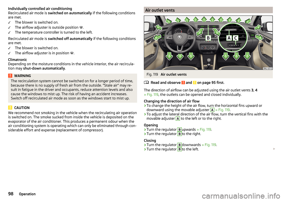
Air outlet vents
Read and observe
and on page 95 first.
The direction of airflow can be adjusted using the air outlet vents 3, 4
» Fig. 119 , the outlets can be opened and closed individually.
Changing the direction of air flow
›
To change the height of the air flow, turn the horizontal fins upward or
downward using the movable adjuster
A
» Fig. 119 .
›
To adjust the lateral direction of the air flow, turn the vertical fins with the
movable adjuster
A
to the left or to the right.
Opening
›
Turn the regulator
B
upwards » Fig. 119.
›
Turn the regulator
B
to the right.
Closing
›
Turn the regulator
B
downwards » Fig. 119.
›
Turn the regulator
B
to the left.
98Operation
Page 101 of 220
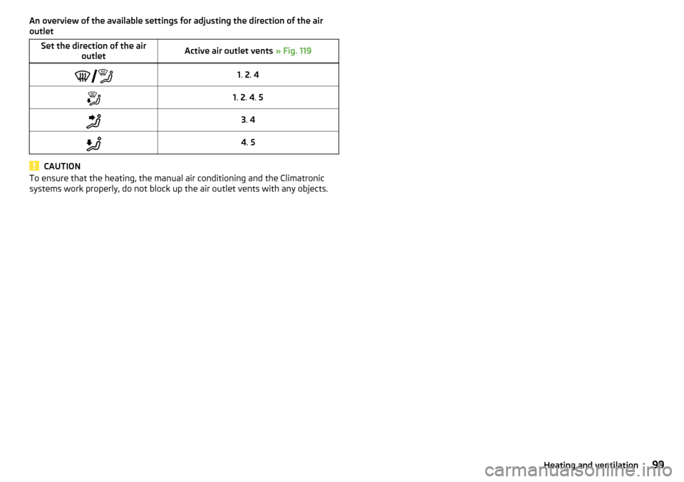
An overview of the available settings for adjusting the direction of the air
outletSet the direction of the air outletActive air outlet vents » Fig. 1191. 2 . 41. 2 . 4 . 53 . 44 . 5
CAUTION
To ensure that the heating, the manual air conditioning and the Climatronic
systems work properly, do not block up the air outlet vents with any objects.99Heating and ventilation
Page 107 of 220
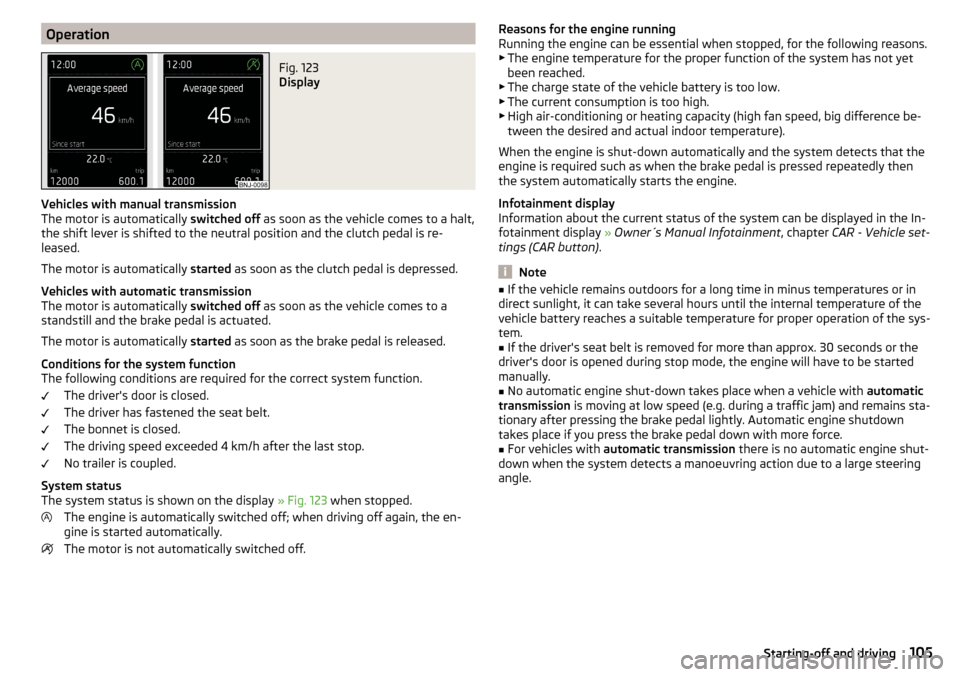
OperationFig. 123
Display
Vehicles with manual transmission
The motor is automatically switched off as soon as the vehicle comes to a halt,
the shift lever is shifted to the neutral position and the clutch pedal is re-
leased.
The motor is automatically started as soon as the clutch pedal is depressed.
Vehicles with automatic transmission
The motor is automatically switched off as soon as the vehicle comes to a
standstill and the brake pedal is actuated.
The motor is automatically started as soon as the brake pedal is released.
Conditions for the system function
The following conditions are required for the correct system function.
The driver's door is closed.
The driver has fastened the seat belt.
The bonnet is closed.
The driving speed exceeded 4 km/h after the last stop.
No trailer is coupled.
System status
The system status is shown on the display » Fig. 123 when stopped.
The engine is automatically switched off; when driving off again, the en-
gine is started automatically.
The motor is not automatically switched off.
Reasons for the engine running
Running the engine can be essential when stopped, for the following reasons. ▶ The engine temperature for the proper function of the system has not yet
been reached.
▶ The charge state of the vehicle battery is too low.
▶ The current consumption is too high.
▶ High air-conditioning or heating capacity (high fan speed, big difference be-
tween the desired and actual indoor temperature).
When the engine is shut-down automatically and the system detects that the
engine is required such as when the brake pedal is pressed repeatedly then
the system automatically starts the engine.
Infotainment display
Information about the current status of the system can be displayed in the In-
fotainment display » Owner´s Manual Infotainment , chapter CAR - Vehicle set-
tings (CAR button) .
Note
■
If the vehicle remains outdoors for a long time in minus temperatures or in
direct sunlight, it can take several hours until the internal temperature of the
vehicle battery reaches a suitable temperature for proper operation of the sys-
tem.■
If the driver's seat belt is removed for more than approx. 30 seconds or the
driver's door is opened during stop mode, the engine will have to be started
manually.
■
No automatic engine shut-down takes place when a vehicle with automatic
transmission is moving at low speed (e.g. during a traffic jam) and remains sta-
tionary after pressing the brake pedal lightly. Automatic engine shutdown
takes place if you press the brake pedal down with more force.
■
For vehicles with automatic transmission there is no automatic engine shut-
down when the system detects a manoeuvring action due to a large steering
angle.
105Starting-off and driving
Page 108 of 220
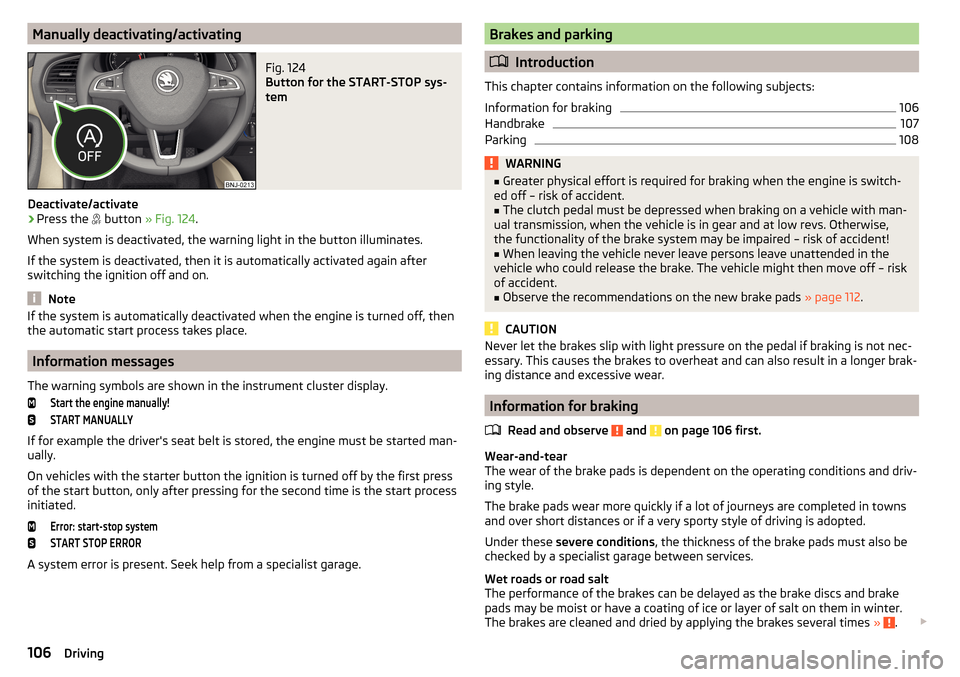
Manually deactivating/activatingFig. 124
Button for the START-STOP sys-
tem
Deactivate/activate
›
Press the button
» Fig. 124 .
When system is deactivated, the warning light in the button illuminates.
If the system is deactivated, then it is automatically activated again after
switching the ignition off and on.
Note
If the system is automatically deactivated when the engine is turned off, then
the automatic start process takes place.
Information messages
The warning symbols are shown in the instrument cluster display.
Start the engine manually!START MANUALLY
If for example the driver's seat belt is stored, the engine must be started man-
ually.
On vehicles with the starter button the ignition is turned off by the first press
of the start button, only after pressing for the second time is the start process
initiated.
Error: start-stop systemSTART STOP ERROR
A system error is present. Seek help from a specialist garage.
Brakes and parking
Introduction
This chapter contains information on the following subjects:
Information for braking
106
Handbrake
107
Parking
108WARNING■ Greater physical effort is required for braking when the engine is switch-
ed off – risk of accident.■
The clutch pedal must be depressed when braking on a vehicle with man-
ual transmission, when the vehicle is in gear and at low revs. Otherwise,
the functionality of the brake system may be impaired – risk of accident!
■
When leaving the vehicle never leave persons leave unattended in the
vehicle who could release the brake. The vehicle might then move off – risk
of accident.
■
Observe the recommendations on the new brake pads » page 112.
CAUTION
Never let the brakes slip with light pressure on the pedal if braking is not nec-
essary. This causes the brakes to overheat and can also result in a longer brak-
ing distance and excessive wear.
Information for braking
Read and observe
and on page 106 first.
Wear-and-tear
The wear of the brake pads is dependent on the operating conditions and driv-
ing style.
The brake pads wear more quickly if a lot of journeys are completed in towns
and over short distances or if a very sporty style of driving is adopted.
Under these severe conditions , the thickness of the brake pads must also be
checked by a specialist garage between services.
Wet roads or road salt
The performance of the brakes can be delayed as the brake discs and brake
pads may be moist or have a coating of ice or layer of salt on them in winter.
The brakes are cleaned and dried by applying the brakes several times »
.
106Driving
Page 114 of 220
Drive especially carefully for the first 500 km or so.
New brake pads
New brake pads have to first “grind in” because these do not initially have the
best possible braking effect.
Drive especially carefully for the first 200 km or so.
Tips for economical driving
To achieve the lowest possible fuel consumption, the following instructions
must be observed.
Looking ahead when driving
Avoid unnecessary acceleration and braking.
Change gear in an energy saving and timely manner
Observe the recommended gear » page 39.
Avoid full throttle and high speeds
Fuel consumption can be reduced by half if only three-quarters of the possible
top speed of your vehicle is used.
Reducing idling
If the vehicle is fitted with the START - STOP system there is an automatic re-
duction of the idling. If the engine is stopped on vehicles without START-STOP
system, such as when waiting in a traffic jam, the fuel economy is already
greater after 30 - 40 s than the fuel quantity which is required for engine re-
start.
Avoid short distances
When driving a short distance of less than about 4 km, the engine cannot
reach its operating temperature. As long as the engine has not reached oper-
ating temperature, the fuel consumption is significantly higher than with the
engine hot.
Pay attention to the correct tyre inflation pressure being maintained
Further information » page 161.
Avoid unnecessary ballast
Per 100 kg of weight, consumption increases by about 0.3 l/100 km. At a speed
of 100 - 120 km/h, a vehicle fitted with a roof rack cross member without a load
will use about 10 % more fuel than normal due to the increased aerodynamic
drag.
Saving electricity
Only turn on electrical consumers (e.g. seat, window and mirror heating, etc.)
for as long as necessary.
Use the cooling system economically
The air conditioning system compressor uses power from the engine when in
cooling mode, which will affect the fuel consumption.
It recommended to open the windows or the doors of a vehicle for which the
interior has been strongly heated through the effect of direct sunlight in order
to allow the heated air to escape.
The cooling system should not be switched on if the windows are open.
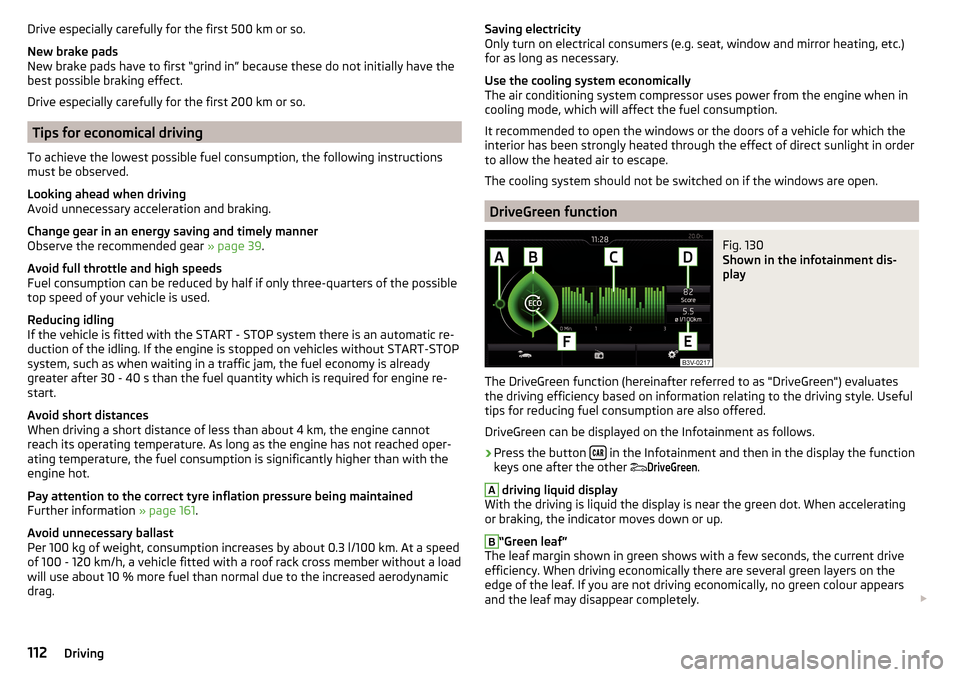
DriveGreen function
Fig. 130
Shown in the infotainment dis-
play
The DriveGreen function (hereinafter referred to as "DriveGreen") evaluates
the driving efficiency based on information relating to the driving style. Useful
tips for reducing fuel consumption are also offered.
DriveGreen can be displayed on the Infotainment as follows.
›
Press the button in the Infotainment and then in the display the function
keys one after the other
DriveGreen
.
A
driving liquid display
With the driving is liquid the display is near the green dot. When accelerating
or braking, the indicator moves down or up.
B
“Green leaf”
The leaf margin shown in green shows with a few seconds, the current drive
efficiency. When driving economically there are several green layers on the
edge of the leaf. If you are not driving economically, no green colour appears
and the leaf may disappear completely.
112Driving
Page 116 of 220
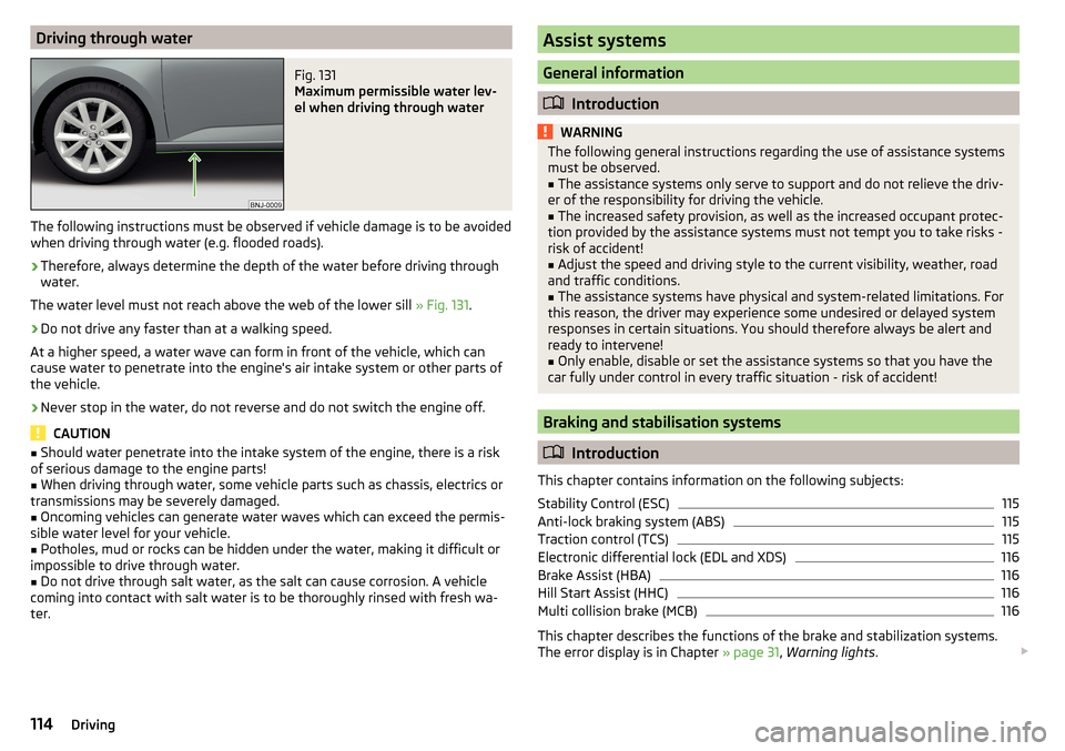
Driving through waterFig. 131
Maximum permissible water lev-
el when driving through water
The following instructions must be observed if vehicle damage is to be avoided
when driving through water (e.g. flooded roads).
›
Therefore, always determine the depth of the water before driving through
water.
The water level must not reach above the web of the lower sill » Fig. 131.
›
Do not drive any faster than at a walking speed.
At a higher speed, a water wave can form in front of the vehicle, which can
cause water to penetrate into the engine's air intake system or other parts of
the vehicle.
›
Never stop in the water, do not reverse and do not switch the engine off.
CAUTION
■ Should water penetrate into the intake system of the engine, there is a risk
of serious damage to the engine parts!■
When driving through water, some vehicle parts such as chassis, electrics or
transmissions may be severely damaged.
■
Oncoming vehicles can generate water waves which can exceed the permis-
sible water level for your vehicle.
■
Potholes, mud or rocks can be hidden under the water, making it difficult or
impossible to drive through water.
■
Do not drive through salt water, as the salt can cause corrosion. A vehicle
coming into contact with salt water is to be thoroughly rinsed with fresh wa-
ter.
Assist systems
General information
Introduction
WARNINGThe following general instructions regarding the use of assistance systems
must be observed.■
The assistance systems only serve to support and do not relieve the driv-
er of the responsibility for driving the vehicle.
■
The increased safety provision, as well as the increased occupant protec-
tion provided by the assistance systems must not tempt you to take risks -
risk of accident!
■
Adjust the speed and driving style to the current visibility, weather, road
and traffic conditions.
■
The assistance systems have physical and system-related limitations. For
this reason, the driver may experience some undesired or delayed system
responses in certain situations. You should therefore always be alert and
ready to intervene!
■
Only enable, disable or set the assistance systems so that you have the
car fully under control in every traffic situation - risk of accident!
Braking and stabilisation systems
Introduction
This chapter contains information on the following subjects:
Stability Control (ESC)
115
Anti-lock braking system (ABS)
115
Traction control (TCS)
115
Electronic differential lock (EDL and XDS)
116
Brake Assist (HBA)
116
Hill Start Assist (HHC)
116
Multi collision brake (MCB)
116
This chapter describes the functions of the brake and stabilization systems.
The error display is in Chapter » page 31, Warning lights .
114Driving
Page 119 of 220
WARNING (Continued)■External noise sources may affect the signals of the system sensors. Un-
der adverse conditions, this may cause objects or people to be not recog-
nised by the system.■
Before reversing, you should make sure that there are no small obstacles,
such as rocks, thin posts, trailer drawbars etc. in front or behind your vehi-
cle. Such obstacles may not be recognised by the system sensors.
CAUTION
■ Keep the system sensors » Fig. 133 on page 117 clean, snow-and ice-free and
do not cover with any objects of any kind, otherwise the system functioning
may be impaired.■
Under adverse weather conditions (heavy rain, water vapour, very low or
high temperatures, etc.), the system function may be limited - “incorrect recog-
nition of obstacle”.
■
Accessories additionally installed on the vehicle rear, such as bicycle carriers,
can impair the system function.
Function
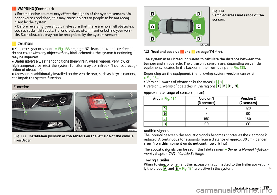
Fig. 133
Installation position of the sensors on the left side of the vehicle:
front/rear
Fig. 134
Sampled areas and range of the
sensors
Read and observe and on page 116 first.
The system uses ultrasound waves to calculate the distance between the
bumper and an obstacle. The ultrasonic sensors are, depending on vehicle
equipment,, located in the back or in the front bumper » Fig. 133.
Depending on the equipment, the following system versions can exist
» Fig. 134 .
▶ Version 1: warns of obstacles in the areas
C
,
D
.
▶ Version 2: warns of obstacles in the regions
A
,
B
,
C
,
D
.
Approximate range of sensors (in cm)
Area » Fig. 134Version 1
(3 sensors)Version 2
(7 sensors)A-120B-60C160160D6060
Audible signals
The interval between the acoustic signals becomes shorter as the clearance is
reduced. A continuous tone sounds from a distance of approx. 30 cm - danger
area. From this moment on do not continue driving!
The acoustic signals can be set in the Infotainment » Owner´s Manual Infotain-
ment , chapter CAR - Vehicle Settings .
Towing a trailer
When towing, or when another accessory is connected to the trailer socket on-
ly the areas
A
and
B
» Fig. 134 are active in the system.
117Assist systems
Page 122 of 220
Basic requirements for starting the controlThe CCS is activated.
On vehicles with a manual transmission , the second gear or higher is en-
gaged.
On vehicles with an automatic transmission , the selector lever is in the
D/S position or in the Tiptronic position.
The current speed is higher than approx. 20 km/h.
This is only possible within the range which is permitted by the power output
and braking power of the engine.WARNINGIf the engine power and engine braking effect is insufficient to maintain
the set speed, vehicle operation must be taken over!
Operating Description
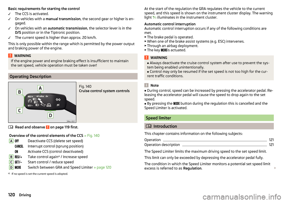
Fig. 140
Cruise control system controls
Read and observe on page 119 first.
Overview of the control elements of the CCS » Fig. 140ADeactivate CCS (delete set speed) Interrupt control (sprung position) Activate CCS (control deactivated)BTake control again a)
/ Increase speedCStart control / reduce speedDSwitch between GRA and Speed Limiter » page 120a)
If no speed is set the current speed is adopted.
At the start of the regulation the GRA regulates the vehicle to the current
speed, and this speed is shown on the instrument cluster display. The warning
light
illuminates in the instrument cluster.
Automatic control interruption
Automatic control interruption occurs if any of the following conditions are
met.
▶ The brake pedal is operated.
▶ When one of the brake assist systems (e.g. ESC) intervenes.
▶ Through an airbag deployment.
▶ The key
is actuated.WARNING■
Always deactivate the cruise control system after use to prevent the sys-
tem being enabled unintentionally.■
Control may only be resumed if the set speed is not too high for the cur-
rent traffic conditions.
Note
■ During control, speed can be increased by pressing the accelerator pedal. Re-
leasing the accelerator pedal will cause the speed to drop again to the set
speed.■
By pressing the
button during the regulation this is cancelled and the
Speed Limiter is activated.
Speed limiter
Introduction
This chapter contains information on the following subjects:
Operation
121
Operation description
121
The Speed Limiter limits the maximum driving speed to the set speed limit.
This limit can only be exceeded by depressing the accelerator pedal fully.
The condition in which the Speed Limiter monitors a potential set speed limit
excess is referred to as Regulation.
120Driving
Page 125 of 220
CAUTIONRemove the snow with a brush and the ice with a solvent-free de-icer.
OperationRead and observe
and on page 122 first.
The system support is provided in the following manner.▶ Alerts you about a dangerous proximity to the vehicle ahead.
▶ Warns you of an impending collision.
▶ Prepares the brakes for emergency braking prior to a detected danger.
▶ Assists with a brake action triggered by the driver.
▶ If the driver fails to respond to a detected danger, an automatic braking ac-
tion is performed.
The system can work only if the following basic conditions are met. The system is activated.
The TCS is activated » page 115, Traction control (TCS) .
The vehicle is moving forwards at a speed of more than approx. 5 km/h.
Note
The system can be impaired or may not be available, for example when driving
in “sharp ”curves or with an ESC engagement » page 115.
Distance warning (dangerous distance)
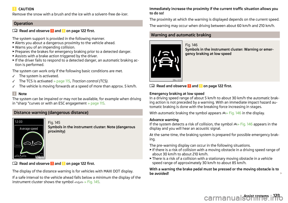
Fig. 145
Symbols in the instrument cluster: Note (dangerous
proximity)
Read and observe and on page 122 first.
The display of the distance warning is for vehicles with MAXI DOT display.
If a safe interval to the vehicle ahead falls below a minimum the display of the
instrument cluster shows the symbol
» Fig. 145 .
Immediately increase the proximity if the current traffic situation allows you
to do so!
The proximity at which the warning is displayed depends on the current speed.
The warning may occur when driving between about 60 km/h and 210 km/h.
Warning and automatic braking
Fig. 146
Symbols in the instrument cluster: Warning or emer-
gency braking at low speed
Read and observe and on page 122 first.
Emergency braking at low speed
In a driving speed range of about 5 km/h to about 30 km/h the automatic brak-
ing action is not preceded by a warning. With an immediate impact hazard au-
tomatic braking is done with the breaking force increasing in stages.
With automatic braking the symbol appears » Fig. 146
in the display.
Advance warning
If the system detects a risk of collision, the symbol » Fig. 146
appears in the
display and you will hear an acoustic signal.
At the same time, the braking system is prepared for possible emergency brak- ing.
The pre-warning display can occur in the following situations. ▶ If there is a risk of collision with a moving obstacle in a driving speed range of
about 30 km/h to about 210 km/h.
▶ There is a risk of a collision with a stationary moving obstacle in a vehicle
speed range of approximately 30 km/h to about 85 km/h.
With a warning the brake pedal must be pressed or the moving obstacle is to
be avoided!
123Assist systems