check engine SKODA FABIA 2015 3.G / NJ Owner's Guide
[x] Cancel search | Manufacturer: SKODA, Model Year: 2015, Model line: FABIA, Model: SKODA FABIA 2015 3.G / NJPages: 220, PDF Size: 32.46 MB
Page 161 of 220
WARNING■When you charge a battery, hydrogen is released, and a highly explosive
gas mixture is also produced. An explosion can be caused through sparkling
over during unclamping or loosening of the cable plug while the ignition is
on.■
Creating a bridge between the poles on the battery (e.g. with metal ob-
jects - cables) creates a short circuit - risk of damage to the battery, explo-
sion and burning of the battery, jets of acid spurting out.
■
Avoid creating sparks when working with cables and electrical devices.
Strong sparking represents a risk of injury.
■
Before carrying out any work on the electrical system, switch off the en-
gine, the ignition and all electrical consumers and disconnect the negative
terminal
.
■
“Quick-charging” the vehicle battery is dangerous and requires a special
charger and specialist knowledge.
■
We therefore recommend that vehicle batteries be “rapidly charged” by a
specialist garage.
CAUTION
On vehicles with the START/STOP system or additional heating (auxiliary heat-
ing), the pole terminal of the charger must not be connected directly to the
negative terminal of the vehicle battery, but only to the engine earth
» page 174 .
Replacing
Read and observe
and on page 157 first.
The new vehicle battery must have the same capacity, voltage, current and thesame size as the original battery. Suitable vehicle battery types can be pur-
chased from a specialist garage.
We recommend you have the battery replaced by a specialist garage.
Disconnecting or reconnecting
Read and observe
and on page 157 first.
Disconnecting
›
Switch off the ignition.
›
First, disconnect the negative terminal
first, then the positive
terminal
of the battery.
Connecting›First, connect the positive first, then the negative battery terminal.
After disconnecting and re-connecting the vehicle battery, the following func-
tions or devices are partially or completely inoperative.Function / deviceOperating measureElectric windows» page 59Time settings» page 31
CAUTION
■ Disconnect the vehicle battery only with the ignition turned off - there is a
risk of damaging the electrical system of the vehicle.■
Under no circumstances must the battery cables be connected incorrectly –
risk of a cable fire.
Note
■ After disconnecting and re-connecting the vehicle battery, we recommend
having the vehicle checked by a specialist to ensure that the full functionality
of all electrical systems is guaranteed.■
The data of the multi-function display will be reset.
Automatic load deactivation
Read and observe
and on page 157 first.
The vehicle voltage system automatically prevents the battery from discharg-ing when the battery is put under high levels of strain. This may be noticed
from the following.
▶ The idling speed is raised to allow the generator to deliver more electricity to
the electrical system.
▶ Where appropriate large convenience consumers, e.g. seat heaters, rear win-
dow heaters, have their power limited or shut off completely if necessary.
CAUTION
■ Despite such intervention by the vehicle electric system management, the
vehicle battery may be drained. For example, when the ignition is switched on
a long time with the engine turned off or the side or parking lights are turned
on during longer parking.■
Consumers which are supplied via a 12 V socket can cause the vehicle battery
to discharge when the ignition is switched off.
159Inspecting and replenishing
Page 173 of 220
WARNING■If the wheel has to be changed on a slope, first of all block the opposite
wheel with a stone or similar object to prevent the vehicle from unexpect-
edly rolling away.■
Secure the base plate of the lifting jack with suitable means to prevent
possible moving. A soft and slippery ground under the base plate may move
the lifting jack, causing the vehicle to fall down. It is therefore always nec-
essary to place the lifting jack on a solid surface or use a wide and stable
base. Use a non-slip base (e.g. a rubber foot mat) if the surface is smooth,
such as cobbled stones, tiled floor, etc.
■
Only attach the lifting jack to the attachment points provided for this pur-
pose.
■
Always raise the vehicle with the doors closed.
■
Never position any body parts, such as arms or legs under the vehicle,
while the vehicle is raised with a lifting jack.
■
When the vehicle is raised, never start the engine.
CAUTION
Make sure that the jack is attached correctly to the web on the lower sil, oth-
erwise there is a risk of damage to the vehicle.
Remove the wheel / fix
When changing a wheel, the following instructions must be followed.
›
Remove the full wheel trim or the caps of the wheel bolts.
›
First of all slacken the anti-theft wheel bolt and then the other wheel bolts.
›
Jack up the vehicle until the wheel that needs changing is clear of the
ground.
›
Unscrew the wheel bolts and place them on a clean surface (cloth, paper,
etc.).
›
Remove the wheel carefully.
›
Attach the wheel and slightly screw on the wheel bolts.
›
Lower the vehicle.
›
Tighten the opposite wheel bolts alternately (cross-wise) with the wheel
wrench. Tighten the anti-theft wheel bolt last.
›
Replace the wheel trim or the caps.
When fitting unidirectional tyres, ensure that the direction of rotation is cor-
rect » page 163 .
All bolts must be clean and must turn easily.
If it is established when changing a wheel that the wheel bolts are corroded and difficult to move, then these must be replaced.
Under no circumstances should you grease or oil the wheel bolts!WARNINGUndo the wheel bolts only a little (about one turn) until the vehicle has
been jacked up. Otherwise the wheel could become loose and fall off.
Subsequent steps
After changing the wheel, the following work should be carried out.
›
Stow the replaced wheel in the wheel well and secure it with a special screw.
›
Stow the tool kit in the space provided and secure using the strap.
›
Check the tyre pressure on the installed wheel as soon as possible.
›
Have the tightening torque of the wheel bolts checked with a torque wrench
as soon as possible.
After changing the wheel, the tyre pressure should be adjusted. In vehicles
with tyre pressure monitoring, save tyre pressure values » page 126.
Change the damaged wheel or consult a specialist garage about repair possi-
bilities.
The prescribed tightening torque of the wheel bolts is 120 Nm.
WARNING■
If the wheel bolts are tightened to a too low tightening torque, the rim
can come loose when the car is moving. A tightening torque which is too
high can damage the bolts and threads and this can result in permanent
deformation of the contact surfaces on the rim.■
Drive cautiously and only at a moderate speed until the tightening torque
has been checked.
Breakdown kit
Introduction
This chapter contains information on the following subjects:
Components of the puncture repair kit
172
General information
172
Preparations for using the breakdown kit
173
171Emergency equipment, and self-help
Page 175 of 220
▶The cut or puncture is larger than 4 mm.
▶ The tyre wall is damaged.
▶ After the expiration date (see inflation bottle).
Preparations for using the breakdown kit
Read and observe
on page 172 first.
The following preparatory work must be carried out before using the break-
down kit.
›
Switch off the engine.
›
On vehicles with Manual transmission select 1st gear .
›
On vehicles with automatic transmission place the selector lever in the P po-
sition.
›
Firmly apply the handbrake.
›
Check that you can carry out the repairs with the breakdown kit » page 172,
General information .
›
Uncouple trailer, if attached.
›
Remove the breakdown kit from the boot.
›
Stick the corresponding sticker
1
» Fig. 186 on page 172 on the dashboard in
the driver's field of view.
›
Unscrew the valve cap.
›
Use the valve remover
2
to unscrew the valve core and place it on a clean
surface (rag, paper, etc.).
Sealing and inflating the tyre
Read and observe
on page 172 first.
Sealing
›
Shake the tyre inflator bottle
10
» Fig. 186 on page 172 vigorously several
times.
›
Firmly screw the inflation hose
3
onto the tyre inflater bottle
10
. The film on
the cap is pierced automatically.
›
Remove the plug from the inflation hose
3
and push the open end fully on-
to the tyre valve.
›
Hold the bottle
10
with the bottom facing upwards and fill all of the sealing
agent from the tyre inflator bottle into the tyre.
›
Remove the filler plug from the tyre valve.
›
Screw the valve core back into the tyre valve using the valve remover
2
.
Inflating›Screw the air compressor tyre inflation hose 7 » Fig. 186 on page 172 firmly
onto the tyre valve.›
On vehicles with manual transmission , move the lever to the neutral posi-
tion.
›
On vehicles with automatic transmission place the selector lever in the P po-
sition.
›
Start the engine and run it in idle.
›
Plug the connector
6
into 12 volt socket » page 77.
›
Switch on the air compressor with the ON and OFF switch
9
.
›
Allow the air compressor to run until a pressure of 2.0 - 2.5 bar is achieved.
Maximum run time of 8 minutes » .
›
Switch off the air compressor.
›
If you cannot reach an air pressure of 2.0 - 2.5 bar, unscrew the tyre inflation
hose
7
from the tyre valve.
›
Drive the vehicle 10 metres forwards or backwards to allow the sealing agent
to “distribute” in the tyre.
›
Firmly screw the tyre inflation hose
7
back onto the tyre valve and repeat
the inflation process.
›
Switch off the air compressor.
›
Remove the tyre inflation hose
7
from the tyre valve.
Once a tyre inflation pressure of 2.0 - 2.5 bar is achieved, you can continue the journey.
WARNING■ If the tyre does not inflate to at least. 2.0 bar, the damage is too great.
The sealing agent cannot be used to seal the tyre. Do not drive the vehi-
cle! Seek help from a specialist garage.■
The tyre inflation hose and air compressor may get hot while the tyre is
being inflated – there is a risk of injury.
CAUTION
Switch off the air compressor after running 8 minutes at the most – risk of
overheating. Allow the air compressor to cool a few minutes before switching
it on again.
Notes for driving with tyre repaired
Read and observe
on page 172 first.
The filling pressure of the repaired tyre is a 10-minute test drive.
173Emergency equipment, and self-help
Page 183 of 220
Fuses and light bulbs
Fuses
Introduction
This chapter contains information on the following subjects:
Fuses in the dash panel
181
Assignment of the fuses in the dash panel
182
Fuses in the engine compartment
183
Fuse assignment in the engine compartment
183
Individual electrical circuits are protected by fuses.
Switch off the ignition and the corresponding power consuming device before
replacing a fuse.
Find out which fuse belongs to the component that is not operating
» page 181 , Fuses in the dash panel or » page 183 , Fuses in the engine com-
partment .
Fuse colourMaximum amperagepurple3light brown5dark brown7.5red10blue15yellow/blue20white25green/pink30green40red50WARNINGAlways read and observe the warnings before completing any work in the
engine compartment » page 149.CAUTION■
“Never repair” fuses or replace them with a fuse of a higher amperage – risk
of fire. This may also cause damage at another part of the electrical system.■
If a newly inserted fuse blows again after a short time, have the electrical
system checked as quickly as possible by a specialist garage.
■
A blown fuse is recognisable by the molten metal strip. Replace the faulty
fuse with a new one of the same amperage.
Note
■
We recommend that you always carry replacement fuses in the vehicle. A box
of replacement fuses and bulbs can be purchased from ŠKODA Original Acces-
sories.■
One fuse may cover several consumers.
■
A single consumer may use several fuses.
Fuses in the dash panel
Fig. 199
Remove the cover
Read and observe and on page 181 first.
The fuses are located on the bottom of the dash panel behind a cover.
Replacing fuses
›
Remove the cover of the fuse box » Fig. 199 in the direction of the arrow.
›
Remove the plastic clip from the holder in the fuse box cover.
›
Place the clamp on the respective fuse and pull this fuse out.
›
Insert a new fuse.
›
Replace the clamp in the original position.
›
Insert the top edge of the cover into the dash panel first.
›
Push the lower edge of the cover in the region
A
.
181Fuses and light bulbs
Page 186 of 220
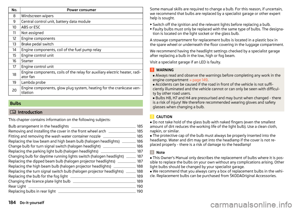
No.Power consumer8Windscreen wipers9Central control unit, battery data module10ABS or ESC11Not assigned12Engine components13Brake pedal switch14Engine components, coil of the fuel pump relay15Engine control unit16Starter17Engine control unit18Engine components, coils of the relay for auxiliary electric heater, radi-
ator fan19Lambda probe20Engine components, glow plug system, heating for the crankcase ven-
tilation
Bulbs
Introduction
This chapter contains information on the following subjects:
Bulb arrangement in the headlights
185
Removing and installing the cover in the front wheel arch
185
Fitting and removing the wash water container nozzle
185
Replacing the low beam and high beam bulb (halogen headlights)
186
Change bulb for turn signal switch (halogen headlight)
186
Replacing the parking light bulb (halogen headlights)
187
Changing bulb for daytime running lights switch (halogen headlight)
187
Replacing the dipped beam bulb (halogen projector headlights)
187
Replacing the high beam bulb (halogen projector headlights)
188
Replacing the turn signal switch bulb (halogen projector headlights)
188
Replacing the bulb for the fog light
189
Changing the licence plate light bulb
189
Rear Light
190
Replacing bulbs in rear light
190Some manual skills are required to change a bulb. For this reason, if uncertain,
we recommend that bulbs are replaced by a specialist garage or other expert
help is sought.
▶ Switch off the ignition and the relevant lights before replacing a bulb.
▶ Faulty bulbs must only be replaced with the same type of bulbs. The designa-
tion is located on the light socket or the glass bulb.
A stowage compartment for replacement bulbs is located in a plastic box in
the spare wheel or underneath the floor covering in the luggage compartment.
We recommend having the headlight settings checked by a specialist garage
after replacing a bulb in the low, high or fog beam.
Visit a specialist garage if an LED is faulty.WARNING■ Always read and observe the warnings before completing any work in the
engine compartment » page 149.■
Accidents can be caused if the road in front of the vehicle is not suffi-
ciently illuminated and the vehicle cannot or can only be seen with difficul-
ty by other road users.
■
Bulbs H8, H7 and H4 are pressurised and may burst when changed - there
is a risk of injury! We therefore recommended wearing gloves and safety
glasses when changing a bulb.
CAUTION
■ Do not take hold of the glass bulb with naked fingers (even the smallest
amount of dirt reduces the working life of the light bulb). Use a clean cloth,
napkin, or similar.■
The protective cap of the bulb must always be properly inserted into the
headlamp. Water and dirt may get into the headlamp if the cover is not re-
placed properly - there is a risk of damage to the headlamp!
Note
■ This Owner's Manual only describes the replacement of bulbs where it is pos-
sible to replace the bulbs on your own without any complications arising. Other
light bulbs should be changed by your specialist garage.■
We recommend that you always carry a box of replacement bulbs in the vehi-
cle. Replacement bulbs can be purchased from ŠKODAOriginal Accessories.
184Do-it-yourself
Page 204 of 220
Brake fluid155
Checking156
Information messages32
Brake pedal (automatic transmission) Indicator light
35
Brakes Brake booster
107
Brake fluid156
Braking and stabilisation systems114
Handbrake107
Information messages32
Running-in111
Warning light32
Brakes and parking106
Brake system114
Braking Information for braking
106
Breakdown kit171
Bulbs Replacing
184
Button CAR see Infotainment
4
Button in driver's door electric windows
57
C
Car care Jack
143
Car computer see multifunction display
40
Care and maintenance136
Car park108
Car park ticket holder74
Carrier Roof rack
93
Cavity protection143
Central locking49
Problems54
Central locking button52
Change Bulb for daytime running lights (halogen spot-light)
187
Bulb for indicator (halogen headlight)186
Engine oil152
Light bulb in tail light190
Changing Fuses
181
Fuses in the dash panel181
Licence plate light bulb189
Wheels168
Changing a wheel Preparation
168
Subsequent steps171
Changing wheels Wheel removal and fix
171
Charging a vehicle battery158
Check Fit ball head properly
130
Checking Battery electrolyte level
158
Brake fluid156
Coolant level155
Engine oil153
Oil level153
Windscreen washer fluid152
Checks Statutory checks
136
Children and safety20
Child safety Side airbag
22
Child safety lock53
Child safety seat Use of child safety seats
22
child seat Use of ISOFIX child seats
23
Child seat Classification
22
ISOFIX22
on the front passenger seat21
TOP TETHER24
Chrome parts Refer to vehicle maintenance
142
Cigarette lighter76
Clean Anodized parts
142
Chrome parts142
Cleaning Alcantara
145
and maintaining belts146
artificial leather145
headlight glasses143
materials145
natural leather145
plastic parts142
seats covers of the electrically heated seats146
wheels143
Cleaning safety belt
146
Cleaning seat covers
146
Cleaning the interior artificial leather
145
Seat covers146
Cleaning the vehicle exterior Cavity protection
143
Door locking cylinder143
Headlight glasses143
Towing device144
Under-body protection144
wheels143
Windows and external mirrors142
Cleaning vehicle139
Cleaning vehicle exterior140
Anodized parts142
Chrome parts142
Decorative films141
Plastic parts142
Protective films141
202Index
Page 205 of 220
Rubber seals142
Vehicle paint work141
Wiper blades144
Clean interior Safety belt
146
Climatronic Automatic operation
97
Operating elements96
Recirculated air mode97
Clothes hook81
Cockpit 12-volt power outlet
77
Ashtray76
Cigarette lighter76
General view26
Lighting64
Storage compartments73
useful equipment73
COMING HOME63
compartments73
Component protection138
Components of the puncture repair kit172
Computer see multifunction display
40
Convenience turn signal61
Coolant154
Checking155
Replenishing155
Temperature gauge29
Warning light36
Warning messages36
CORNER See Headlights with CORNER function
62
Correct routing of seat belt
12
Correct seated position8
Front passenger10
Rear seats10
Correct seat position Driver
9
Counter for distance driven30
cruise control operation
119
operation description120
Cup holders76
D
DAY LIGHT see Daylight running lights
60
Daylight running lights60
Dazzle see sun screen of the panoramic roof
66
De-icing windows
142
De-icing rear window65
Deactivating airbags18
Decorative films141
Delayed locking of the boot lid see boot lid
56
Departure angle196
Diesel refer to Fuel
149
Diesel fuel Operation in winter
149
Diesel particulate filter37
information messages37
Digital Clock31
Dipstick153
Display29
Compass points45
Coolant temperature29
Fuel supply30
Gear changes39
Service interval46
Disposal Acceptance and recycling of used vehicles
139
Distance driven30
Distance warning Warning light
38
DoorChild safety lock53
Closing53
Emergency locking178
Emergency locking the driver's door178
Opening53
Door warning39
Drive Driving through water
114
DriveGreen112
driving emissions
194
fuel consumption194
Driving Maximum speed
197
through water114
driving data operation
40
E
Economical driving Tips
112
EDL116
Electrical power windows Button in the rear doors
58
Electric window lifter Window operation malfunctions
59
Electric Windows57
Button in driver's door57
Electronic differential lock (EDL, XDS)116
Electronic immobilizer100
Emergency Changing a wheel
168
Hazard warning light system63
Jump-starting174
Locking the door without a locking cylinder178
Locking the driver's door178
Selector lever-unlocking179
Switch off the engine by pressing a button103
203Index
Page 206 of 220
Towing the vehicle using the tow hitch177
Towing vehicle175
Tyre repair171
Unlocking the driver's door178
Emergency equipment Fire extinguisher
167
First aid kit166
Jack167
Reflective vest166
Vehicle tool kit167
Warning triangle166
Emissions194
Engine Running-in
111
Starting the engine103
Warning messages36
Engine compartment149
Brake fluid156
Overview151
Vehicle battery156
Engine number192
engine oil specification
153
Engine oil152
change152
Checking153
Replenishing154
Warning light37
EPC Warning light
34
ESC Operation
115
Warning light33
Exhaust inspection system Warning light
33
F
Fastening elements
84
Fatigue detection125
Function125
Information messages125
Films141
Fire extinguisher167
First aid kit166
Flexible storage compartment88
Fog lights Warning light
35
Fold variable loading floor up
91
Footmats109
see Footmats109
Force limitation Power windows
58
Front airbag15
Front Assist122
Disable/enable124
Distance warning123
Information messages125
Operation123
Radar sensor122
Warning and automatic braking123
Warning light38
Front fog lights62
fuel lead-free petrol
148
Fuel147
Diesel149
Fuel gauge30
refer to Fuel147
Refuelling147
Warning light35
fuel consumption194
Fuel reserve Warning light
35
Fuses Assignment
181
Assignment of fuses in the dash panel182
Changing181
Colour coding181
Fuse assignment in the engine compartment183
G
Gear change Gear recommendation
39
Information on the selected gear39
Gear changing Gear stick
108
General view Cockpit
26
Genuine parts137
Glasses compartment79
Glow plug system Warning light
34
H
Handbrake
107
Warning light32
Hazard warning light system63
HBA116
Head airbag17
Headlight cleaning system Headlight cleaning system
67
Headlights Bulb arrangement
185
Driving abroad64
Headlight cleaning system67
Headlights with CORNER function62
Headrests70
Adjust height70
Headrest, removing and installing
70
heater Rear window
65
Heater Recirculated air mode
97
204Index
Page 207 of 220
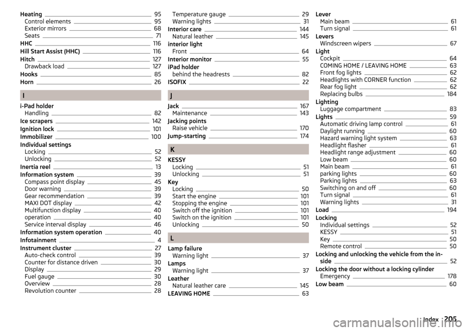
Heating95
Control elements95
Exterior mirrors68
Seats71
HHC116
Hill Start Assist (HHC)116
Hitch127
Drawback load127
Hooks85
Horn26
I
i-Pad holder Handling
82
Ice scrapers142
Ignition lock101
Immobilizer100
Individual settings Locking
52
Unlocking52
Inertia reel13
Information system39
Compass point display45
Door warning39
Gear recommendation39
MAXI DOT display42
Multifunction display40
operation40
Service interval display46
Information system operation40
Infotainment4
Instrument cluster27
Auto-check control39
Counter for distance driven30
Display29
Fuel gauge30
Overview28
Revolution counter28
Temperature gauge29
Warning lights31
Interior care144
Natural leather145
interior light Front
64
Interior monitor55
iPad holder behind the headrests
82
ISOFIX22
J
Jack
167
Maintenance143
Jacking points Raise vehicle
170
Jump-starting174
K
KESSY Locking
51
Unlocking51
Key Locking
50
Start the engine101
Stopping the engine101
Switch off the ignition101
Switch on the ignition101
Unlocking50
L
Lamp failure Warning light
37
Lamps Warning light
37
Leather Natural leather care
145
LEAVING HOME63
Lever Main beam61
Turn signal61
Levers Windscreen wipers
67
Light Cockpit
64
COMING HOME / LEAVING HOME63
Front fog lights62
Headlights with CORNER function62
Rear fog light62
Replacing bulbs184
Lighting Luggage compartment
83
Lights59
Automatic driving lamp control61
Daylight running60
Hazard warning light system63
Headlight flasher61
Headlight range adjustment60
Low beam60
Main beam61
parking lights60
Parking lights63
Switching on and off60
Turn signal61
Warning lights31
Load194
Locking Individual settings
52
KESSY51
Key50
Remote control50
Locking and unlocking the vehicle from the in- side
52
Locking the door without a locking cylinder Emergency
178
Low beam60
205Index