change wheel SKODA FABIA 2015 3.G / NJ Owner's Manual
[x] Cancel search | Manufacturer: SKODA, Model Year: 2015, Model line: FABIA, Model: SKODA FABIA 2015 3.G / NJPages: 220, PDF Size: 32.46 MB
Page 11 of 220
WARNING■The front seats and all head restraints must be adjusted to match body
size at all times and the seat belt must always be fastened properly to pro-
vide the most effective levels of protection to passengers.■
Each occupant must correctly fasten the seat belt belonging to the seat.
Children must be fastened » page 20, Transporting children safely with a
suitable restraint system.
■
By sitting incorrectly, the occupant is risking life-threatening injuries.
■
The seat backrests must not be tilted too far back when driving, as this
will impair the function of the seat belts and of the airbag system – risk of
injury!
Correct seat position of the driver
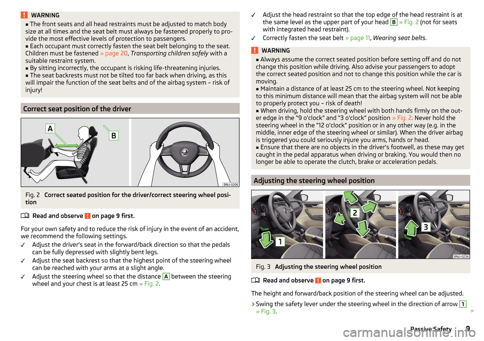
Fig. 2
Correct seated position for the driver/correct steering wheel posi-
tion
Read and observe
on page 9 first.
For your own safety and to reduce the risk of injury in the event of an accident,
we recommend the following settings.
Adjust the driver’s seat in the forward/back direction so that the pedals
can be fully depressed with slightly bent legs.
Adjust the seat backrest so that the highest point of the steering wheel
can be reached with your arms at a slight angle.
Adjust the steering wheel so that the distance
A
between the steering
wheel and your chest is at least 25 cm » Fig. 2.
Adjust the head restraint so that the top edge of the head restraint is at
the same level as the upper part of your head B » Fig. 2 (not for seats
with integrated head restraint).
Correctly fasten the seat belt » page 11, Wearing seat belts .WARNING■
Always assume the correct seated position before setting off and do not
change this position while driving. Also advise your passengers to adopt
the correct seated position and not to change this position while the car is
moving.■
Maintain a distance of at least 25 cm to the steering wheel. Not keeping
to this minimum distance will mean that the airbag system will not be able
to properly protect you – risk of death!
■
When driving, hold the steering wheel with both hands firmly on the out-
er edge in the “9 o'clock” and “3 o'clock” position » Fig. 2. Never hold the
steering wheel in the “12 o'clock” position or in any other way (e.g. in the
middle, inner edge of the steering wheel or similar). When the driver airbag
is triggered you could seriously injure you arms, hands or head.
■
Ensure that there are no objects in the driver's footwell, as these may get
caught in the pedal apparatus when driving or braking. You would then no
longer be able to operate the clutch, brake or acceleration pedals.
Adjusting the steering wheel position
Fig. 3
Adjusting the steering wheel position
Read and observe
on page 9 first.
The height and forward/back position of the steering wheel can be adjusted.
›
Swing the safety lever under the steering wheel in the direction of arrow
1
» Fig. 3 .
9Passive Safety
Page 12 of 220
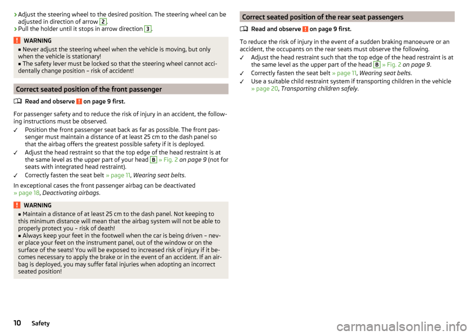
›Adjust the steering wheel to the desired position. The steering wheel can be
adjusted in direction of arrow 2.›
Pull the holder until it stops in arrow direction
3
.
WARNING■ Never adjust the steering wheel when the vehicle is moving, but only
when the vehicle is stationary!■
The safety lever must be locked so that the steering wheel cannot acci-
dentally change position – risk of accident!
Correct seated position of the front passenger
Read and observe
on page 9 first.
For passenger safety and to reduce the risk of injury in an accident, the follow-
ing instructions must be observed.
Position the front passenger seat back as far as possible. The front pas-
senger must maintain a distance of at least 25 cm to the dash panel so
that the airbag offers the greatest possible safety if it is deployed.
Adjust the head restraint so that the top edge of the head restraint is at
the same level as the upper part of your head
B
» Fig. 2 on page 9 (not for
seats with integrated head restraint).
Correctly fasten the seat belt » page 11, Wearing seat belts .
In exceptional cases the front passenger airbag can be deactivated
» page 18 , Deactivating airbags .
WARNING■
Maintain a distance of at least 25 cm to the dash panel. Not keeping to
this minimum distance will mean that the airbag system will not be able to
properly protect you – risk of death!■
Always keep your feet in the footwell when the car is being driven – nev-
er place your feet on the instrument panel, out of the window or on the
surface of the seats! You will be exposed to increased risk of injury if it be-
comes necessary to apply the brake or in the event of an accident. If an air-
bag is deployed, you may suffer fatal injuries when adopting an incorrect
seated position!
Correct seated position of the rear seat passengers
Read and observe
on page 9 first.
To reduce the risk of injury in the event of a sudden braking manoeuvre or an
accident, the occupants on the rear seats must observe the following.
Adjust the head restraint such that the top edge of the head restraint is at
the same level as the upper part of the head
B
» Fig. 2 on page 9 .
Correctly fasten the seat belt » page 11, Wearing seat belts .
Use a suitable child restraint system if transporting children in the vehicle
» page 20 , Transporting children safely .
10Safety
Page 16 of 220
Belt tensioners
Safety for the driver and front passenger wearing their seat belts is enhanced
by the belt tensioners fitted to the inertia reels of the front three-point seat
belts.
If there is a collision the seat belts are tightened by the belt tensioner so that
unwanted body motion is prevented.
The three-point seat belts are automatically tensioned in the event of a frontal
collision of a certain severity.
The front seat belts are automatically tensioned in the event of a side collision
of a certain severity.
Belt tensioners are not activated in the event of minor frontal, side or rear-
end collisions, in the case of a roll-over and also not in accidents in which no
major forces are produced.WARNING■ Any work on the belt tensioner system including removal and installation
of system components because of other repair work, must only be carried
out by a specialist garage.■
If the belt tensioners have been deployed, it is then necessary to replace
the entire system.
Note
■ The belt tensioners can also be deployed if the seat belts are not fastened.■Smoke is generated when the belt tensioners are deployed. This is not an in-
dication of a fire in the vehicle.Airbag system
Description of the airbag system
Introduction
This chapter contains information on the following subjects:
System description
15
Airbag deployment
15
The airbag system supplements the fastened seat belts and provides addition-
al occupant protection in severe frontal and side collisions.
The functional status of the airbag system is indicated by the indicator light
in the instrument cluster » page 34.
WARNING■
An airbag can only offer you optimal protection in combination with a
fastened seat belt .■
The airbag is not a substitute for the seat belt, but instead forms part of
the complete passive vehicle safety concept.
■
To ensure passengers are protected with the greatest possible effect
when the airbag is deployed, the front seats must be correctly adjusted to
match body size » page 8, Correct and safe seated position .
■
If you do not fasten the seat belts when driving, lean too far forward or
adopt an incorrect seated position, you are exposing yourself to increased
risk of injury in the event of an accident.
WARNINGInformation on the use of the airbag system■If there is a fault, have the airbag system checked immediately by a spe-
cialist garage. Otherwise, there is a risk of the airbag not being activated in
the event of an accident.■
No modifications of any kind must be made to parts of the airbag system.
■
Any work on the airbag system including the installation and removal of
system components due to other repair work (e.g. removal of the steering
wheel) must only be carried out by a specialist garage.
■
Never make any changes to the front bumper or the bodywork.
■
Do not manipulate individual parts of the airbag system, as this might re-
sult in the airbag being deployed.
■
The airbag system must then be replaced if the airbag has been deployed.
14Safety
Page 36 of 220
Seek help from a specialist garage.
Glow plug system (diesel engine)Read and observe
on page 32 first.
flashes - there is a fault in the engine management system. The system
makes possible operation emergency mode - there may be a noticeable reduc-
tion in engine performance.
There is a fault in the glow plug system if the warning light
does not come
on or illuminates continuously.
Seek help from a specialist garage.
Engine performance check (petrol engine)
Read and observe
on page 32 first.
illuminates - there is a fault in the engine management system. The system
makes possible operation emergency mode - there may be a noticeable reduc-
tion in engine performance.
Seek help from a specialist garage.
Airbag system
Read and observe
on page 32 first.
System fault
illuminates - there is a fault in the airbag system.
Error: airbagAIRBAG ERROR
Seek help from a specialist garage.
The front passenger airbag has been disabled with the key switch
illuminates for around 4 seconds after the ignition has been switched on.
under the letters
in the middle of the dash panel illumi-
nates after switching on the ignition » page 19.
One of the airbags or a belt tensioner has been disabled by the diagnostic
tool
illuminates for approximately 4 seconds after the ignition is switched on
and then flashes again for approximately 12 seconds.
Airbag/ belt tensioner deactivated.AIRBAG/ BELT TENSIONER OFFWARNINGIf a fault in the airbag system occurs, there is a risk of the system not being
triggered in the event of an accident! Therefore, this must be checked im-
mediately by a specialized garage.
Tyre pressure
Read and observe
on page 32 first.
Change of tyre pressure values
illuminates - there was a pressure change in one of the tyres.
An audible signal sounds as a warning.
›
Immediately reduce speed and avoid sudden steering and braking manoeu-
vres.
›
Stop the vehicle, turn the ignition off and check the tyres and their inflation
pressure » page 161 .
›
Correct the tyre pressure, if necessary or replace the affected wheel
» page 168 or use the repair kit » page 171.
›
Store the tyre pressure values in the system » page 126.
System fault
flashes for approximately 1 minute and remains lit - there may be a fault in
the tyre pressure monitoring system.
›
Stop the vehicle, turn the ignition off and start the engine again.
If the warning light flashes again after the engine has started, there is a
system error.
Seek help from a specialist garage.
Disconnecting the vehicle battery
If the vehicle's battery has been disconnected and reconnected, the indicator
light comes on after switching on the ignition.
The warning light should go out after driving a short distance.
If, after a short drive, the indicator light does not go out, there is a system er-
ror.
Seek help from a specialist garage.
34Operation
Page 37 of 220
Other incidents
The following reasons can also apply if the warning light is illuminated.
▶ The vehicle is loaded on one side. Distribute loads as evenly as possible.
▶ The wheels of one axle are loaded more heavily (e.g. when towing a trailer or
when driving uphill or downhill).
▶ Snow chains are fitted.
▶ A wheel has been changed.
CAUTION
Under certain circumstances (e.g. sporty style of driving, wintry or unpaved
roads) the warning light in the instrument cluster can be delayed or does
not light up at all.
Fuel reserve
Read and observe
on page 32 first.
illuminates - the fuel level in the fuel tank has reached the reserve level (ap-
proximately 7 litres).
Please refuel. Range: ...
kmPLEASE REFUEL RANGE …
km
An audible signal sounds as a warning.
Note
The text in the display goes out after refuelling and driving a short distance.
Turn signal system
Read and observe
on page 32 first.
flashes - the left turn signal is turned on.
flashes - the right turn signal is turned on.
If there is a fault in the turn signal system, the warning light flashes at twice
its normal rate. This does not apply when towing a trailer.
When the hazard warning light system is switched on, this will cause all of the
turn signal lights as well as both warning lights to flash.
Trailer turn signal lights
Read and observe
on page 32 first.
flashes - the trailer lights are switched on.
If a trailer is hitched and the warning light
is not flashing, one of the trailer
turn signal lights has failed.
An example message in the display of the instrument cluster
Trailer: check left turn signal!TRAILER TURN SIG_ CHECK LEFT
Check the trailer bulbs.
Fog lights
Read and observe
on page 32 first.
illuminates - the fog lamps are switched on.
Speed control/speed limiter
Read and observe
on page 32 first.
illuminates - the vehicle speed is limited by the speed regulator system
and/or the automatic distance control or by the speed limiter.
flashes - the speed set with the limiter has been exceeded.
Brake pedal (automatic transmission)
Read and observe
on page 32 first.
illuminates - apply the brake.
Main beam
Read and observe
on page 32 first.
illuminates - the main beam or the headlight flasher is switched on.
35Instruments and warning lights
Page 45 of 220
›Press and hold the dial G on the multifunction steering wheel
» Fig. 31 on
page 43 .
Main menu items (depending on vehicle equipment) ■Driving data
» page 40
■
Assist systems
» page 45
■
Navigation
» page 44
■
Audio
» page 44
■
Telephone
» page 45 ;
■
Vehicle
» page 39 , Auto-check control
The menus can be opened using the buttons on the control lever » Fig. 30 on
page 43 or on the multi-function steering wheel » Fig. 31 on page 43 .
Note
■
If warning messages are displayed, these messages must first be confirmed
to access the main menu.■
The travel mode can be set in the Infotainment » Owner´s Manual Infotain-
ment , chapter Vehicle settings (SETUP button) .
■
For vehicles without Infotainment, the display language can only be adjusted
by a specialist garage.
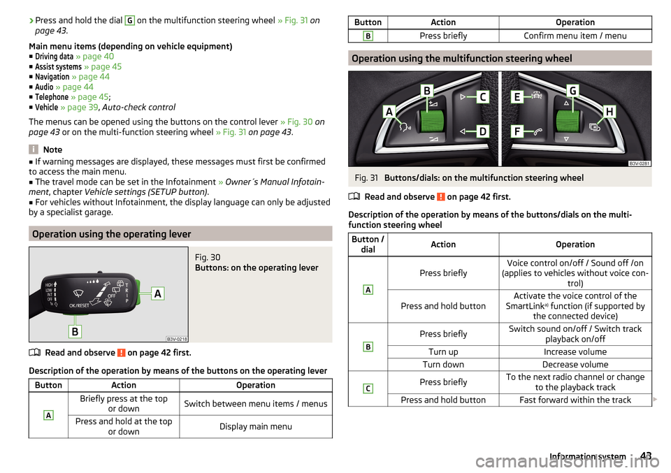
Operation using the operating lever
Fig. 30
Buttons: on the operating lever
Read and observe on page 42 first.
Description of the operation by means of the buttons on the operating lever
ButtonActionOperationABriefly press at the top or downSwitch between menu items / menusPress and hold at the top or downDisplay main menuButtonActionOperationBPress brieflyConfirm menu item / menu
Operation using the multifunction steering wheel
Fig. 31
Buttons/dials: on the multifunction steering wheel
Read and observe
on page 42 first.
Description of the operation by means of the buttons/dials on the multi-
function steering wheel
Button / dialActionOperationA
Press brieflyVoice control on/off / Sound off /on
(applies to vehicles without voice con- trol)Press and hold buttonActivate the voice control of the
SmartLink a)
function (if supported by
the connected device)BPress brieflySwitch sound on/off / Switch track playback on/offTurn upIncrease volumeTurn downDecrease volumeCPress brieflyTo the next radio channel or changeto the playback trackPress and hold buttonFast forward within the track 43Information system
Page 46 of 220
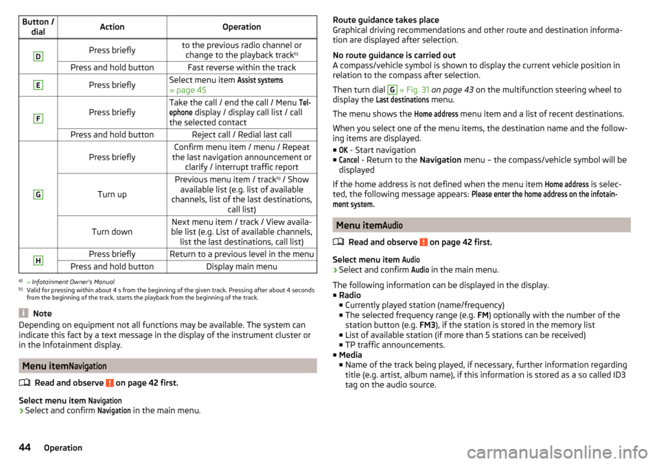
Button /dialActionOperationDPress brieflyto the previous radio channel orchange to the playback track b)Press and hold buttonFast reverse within the trackEPress brieflySelect menu item Assist systems
» page 45
F
Press brieflyTake the call / end the call / Menu Tel-ephone
display / display call list / call
the selected contactPress and hold buttonReject call / Redial last callG
Press brieflyConfirm menu item / menu / Repeat
the last navigation announcement or clarify / interrupt traffic report
Turn up
Previous menu item / track b)
/ Show
available list (e.g. list of available
channels, list of the last destinations, call list)Turn downNext menu item / track / View availa-
ble list (e.g. List of available channels, list the last destinations, call list)HPress brieflyReturn to a previous level in the menuPress and hold buttonDisplay main menua)
» Infotainment Owner's Manual
b)
Valid for pressing within about 4 s from the beginning of the given track. Pressing after about 4 seconds
from the beginning of the track, starts the playback from the beginning of the track.
Note
Depending on equipment not all functions may be available. The system can
indicate this fact by a text message in the display of the instrument cluster or
in the Infotainment display.
Menu item
Navigation
Read and observe on page 42 first.
Select menu item
Navigation›
Select and confirm
Navigation
in the main menu.
Route guidance takes place
Graphical driving recommendations and other route and destination informa-
tion are displayed after selection.
No route guidance is carried out
A compass/vehicle symbol is shown to display the current vehicle position in relation to the compass after selection.
Then turn dial G
» Fig. 31 on page 43 on the multifunction steering wheel to
display the
Last destinations
menu.
The menu shows the
Home address
menu item and a list of recent destinations.
When you select one of the menu items, the destination name and the follow-
ing items are displayed.
■
OK
- Start navigation
■
Cancel
- Return to the Navigation menu – the compass/vehicle symbol will be
displayed
If the home address is not defined when the menu item
Home address
is selec-
ted, the following message appears:
Please enter the home address on the infotain-ment system.
Menu item
Audio
Read and observe on page 42 first.
Select menu item
Audio›
Select and confirm
Audio
in the main menu.
The following information can be displayed in the display.
■ Radio
■ Currently played station (name/frequency)
■ The selected frequency range (e.g. FM) optionally with the number of the
station button (e.g. FM3), if the station is stored in the memory list
■ List of available station (if more than 5 stations can be received)
■ TP traffic announcements.
■ Media
■ Name of the track being played, if necessary, further information regarding
title (e.g. artist, album name), if this information is stored as a so called ID3
tag on the audio source.
44Operation
Page 63 of 220
›Pull the indicator / main beam lever towards the steering wheel, push down
and hold in this position.›
Switch on the ignition.
›
Hold the operating lever in this position for min. 3 seconds after switching on
the ignition.
The deactivation of the function is confirmed by an audible signal.
Activating on vehicles without Infotainment
›
Switch off the ignition.
›
Pull the indicator / main beam lever towards the steering wheel, push up and
hold in this position.
›
Switch on the ignition.
›
Hold the operating lever in this position for min. 3 seconds after switching on
the ignition.
The activation of the function is confirmed by an audible signal.
WARNINGAlways switch on the low beam when the visibility is poor.
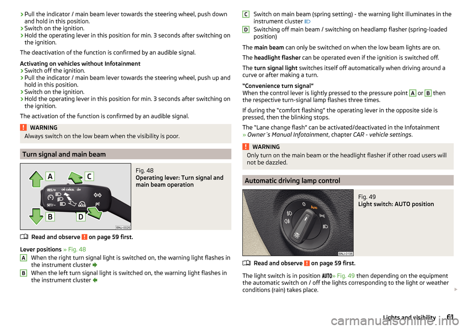
Turn signal and main beam
Fig. 48
Operating lever: Turn signal and
main beam operation
Read and observe on page 59 first.
Lever positions » Fig. 48
When the right turn signal light is switched on, the warning light flashes in
the instrument cluster
When the left turn signal light is switched on, the warning light flashes in
the instrument cluster
ABSwitch on main beam (spring setting) - the warning light illuminates in the
instrument cluster
Switching off main beam / switching on headlamp flasher (spring-loaded
position)
The main beam can only be switched on when the low beam lights are on.
The headlight flasher can be operated even if the ignition is switched off.
The turn signal light switches itself off automatically when driving around a
curve or after making a turn.
“Convenience turn signal”
When the control lever is lightly pressed to the pressure point A
or
B
then
the respective turn-signal lamp flashes three times.
If during the “comfort flashing” the operating lever in the opposite side is
pressed, then the blinking stops.
The “Lane change flash” can be activated/deactivated in the Infotainment
» Owner´s Manual Infotainment , chapter CAR - vehicle settings .
WARNINGOnly turn on the main beam or the headlight flasher if other road users will
not be dazzled.
Automatic driving lamp control
Fig. 49
Light switch: AUTO position
Read and observe on page 59 first.
The light switch is in position
» Fig. 49 then depending on the equipment
the automatic switch on / off the lights corresponding to the light or weather
conditions (rain) takes place.
CD61Lights and visibility
Page 112 of 220
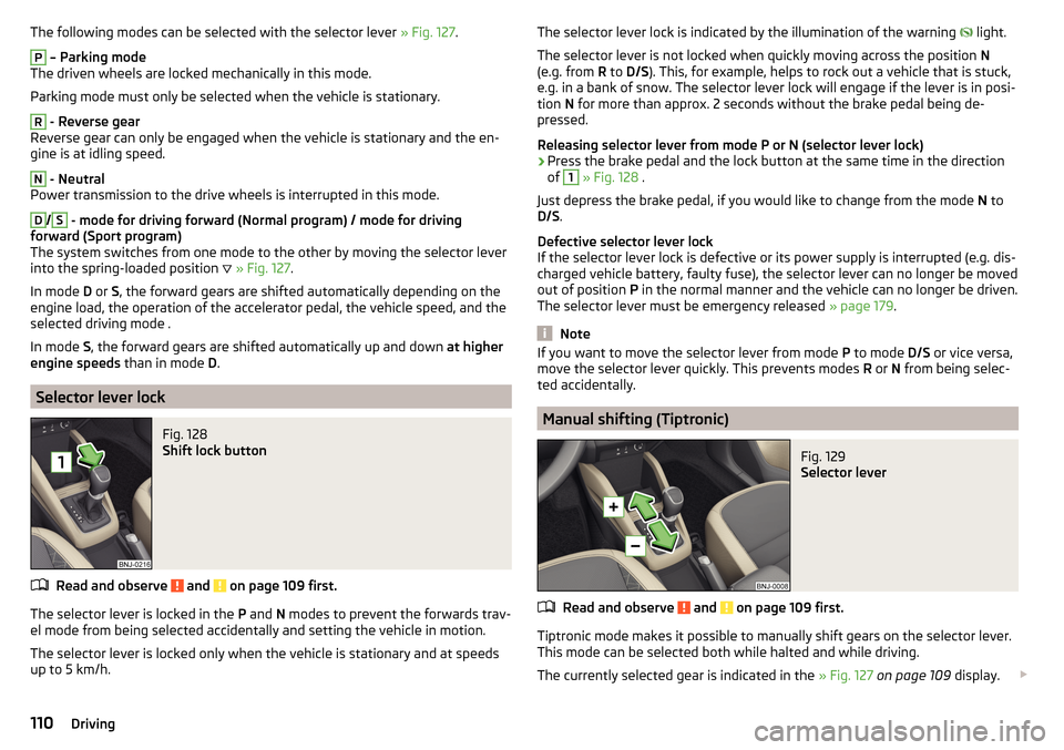
The following modes can be selected with the selector lever » Fig. 127.P
– Parking mode
The driven wheels are locked mechanically in this mode.
Parking mode must only be selected when the vehicle is stationary.
R
- Reverse gear
Reverse gear can only be engaged when the vehicle is stationary and the en-
gine is at idling speed.
N
- Neutral
Power transmission to the drive wheels is interrupted in this mode.
D
/
S
- mode for driving forward (Normal program) / mode for driving
forward (Sport program)
The system switches from one mode to the other by moving the selector lever
into the spring-loaded position
» Fig. 127 .
In mode D or S, the forward gears are shifted automatically depending on the
engine load, the operation of the accelerator pedal, the vehicle speed, and the
selected driving mode .
In mode S, the forward gears are shifted automatically up and down at higher
engine speeds than in mode D.
Selector lever lock
Fig. 128
Shift lock button
Read and observe and on page 109 first.
The selector lever is locked in the P and N modes to prevent the forwards trav-
el mode from being selected accidentally and setting the vehicle in motion.
The selector lever is locked only when the vehicle is stationary and at speeds
up to 5 km/h.
The selector lever lock is indicated by the illumination of the warning light.
The selector lever is not locked when quickly moving across the position N
(e.g. from R to D/S ). This, for example, helps to rock out a vehicle that is stuck,
e.g. in a bank of snow. The selector lever lock will engage if the lever is in posi-
tion N for more than approx. 2 seconds without the brake pedal being de-
pressed.
Releasing selector lever from mode P or N (selector lever lock)›
Press the brake pedal and the lock button at the same time in the direction
of
1
» Fig. 128 .
Just depress the brake pedal, if you would like to change from the mode N to
D/S .
Defective selector lever lock
If the selector lever lock is defective or its power supply is interrupted (e.g. dis-
charged vehicle battery, faulty fuse), the selector lever can no longer be moved
out of position P in the normal manner and the vehicle can no longer be driven.
The selector lever must be emergency released » page 179.
Note
If you want to move the selector lever from mode P to mode D/S or vice versa,
move the selector lever quickly. This prevents modes R or N from being selec-
ted accidentally.
Manual shifting (Tiptronic)
Fig. 129
Selector lever
Read and observe and on page 109 first.
Tiptronic mode makes it possible to manually shift gears on the selector lever. This mode can be selected both while halted and while driving.
The currently selected gear is indicated in the » Fig. 127 on page 109 display.
110Driving
Page 128 of 220
An audible signal is also emitted.
Tyre pressure monitoring
Introduction
This chapter contains information on the following subjects:
Save tyre pressure values
126
Save tyre pressure values and infotainment display
126
Save tyre pressure values by pressing a button
127
The tyre pressure monitoring function (hereinafter known as "system") moni-
tors the tyre pressure while driving.
When changing the tyre inflation pressure, the warning light illuminates in
the instrument cluster and an audible signal is heard.
Information on the procedure for the indication of change in tyre pressure val-
ues » page 34 .
The system can only function properly if the tyres have the prescribed tyre
pressure and this pressure values are stored in the system.
WARNING■ The general information relating to the use of assistance systems must
be observed » page 114, in section Introduction .■
The correct tyre pressure values is always the driver's responsibility. The
tyre pressure should be checked regularly » page 161.
■
The system cannot warn in case of very rapid loss of tyre pressure, e.g. in
the event of a sudden puncture.
Save tyre pressure values
Read and observe
on page 126 first.
The tyre pressure valuesare always stored in the system, if one of the follow-ing events is present. ▶ Change of tyre pressure values.
▶ Change one or more wheels.
▶ Change in position of a wheel on the vehicle.
▶ The warning light in the instrument cluster.
The storage of the tyre pressure values depends on equipment, either in the
infotainment or by pressing a button.WARNINGBefore storing the tyre pressures they must be inflated to the specified in-
flation pressure » page 161. If incorrect pressure values are storedthe sys-
tem may not warn even with a tyre pressure that is too low.
CAUTION
The tyre pressure values should be stored every 10 000 km or once a year to
ensure proper system function.
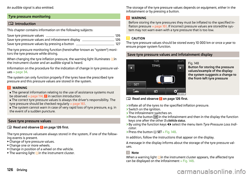
Save tyre pressure values and infotainment display
Fig. 148
Button for storing the pressure
values/example of the display:
the system suggests a change to
the front-left tyre pressure
Read and observe on page 126 first.
›
Inflate all of the tyres to the specified inflation pressure.
›
Switch on the ignition.
›
The Infotainment switches on.
›
Press the button in the Infotainment and then in the display the function
keys one after the other
Vehicle status
.
›
By using the function keys
select the menu item Tyre Pressure Loss Indi-
cator .
›
Press the button
SET
» Fig. 148 .
In addition, follow the instructions that appear on the display.
A message in the display informs about the storage of the tyre pressure val-
ues.
Note
When a warning light in the instrument cluster appears, the affected tyre
can be displayed on the infotainment » Fig. 148.126Driving