inflation pressure SKODA FABIA 2015 3.G / NJ Owner's Manual
[x] Cancel search | Manufacturer: SKODA, Model Year: 2015, Model line: FABIA, Model: SKODA FABIA 2015 3.G / NJPages: 220, PDF Size: 32.46 MB
Page 10 of 220
Safety
Passive Safety
General information
Introduction
This chapter contains information on the following subjects:
Before every journey
8
Driving safety
8
In this section of the instructions you will find important information, tips and
notes on the subject of passive safety.
We have combined everything here which you should be familiar with, for ex-
ample, regarding seat belts, airbags, safety of children and anything similar.
You will find further information on safety, which concerns you and those trav-
elling with you, in the following chapters of this Owner's Manual.
The complete on-board literature should therefore always be in the vehicle.
This particularly applies, if you rent out or sell the vehicle.
Before every journey
For your own safety and the safety of the people travelling with you, please
pay attention to the following points before setting off.
▶ Ensure that the lighting and the turn signal system are functioning properly.
▶ Make sure that the function of the wiper and the condition of the wiper
blades are free of any defects.
▶ Ensure that all of the windows offer good visibility to the outside.
▶ Adjust the rear-view mirror so that vision to the rear is guaranteed.
▶ Ensure that the mirrors are not covered.
▶ Check the tyre inflation pressure.
▶ Check the engine oil, brake fluid and coolant levels.
▶ Secure all items of luggage.
▶ Do not exceed the permissible axle loads and permissible gross weight of the
vehicle – risk of accident.
▶ Close all doors and the engine compartment and luggage compartment lid.
▶ Ensure that no objects can obstruct the pedals.
▶
Protect children in suitable child seats with correctly fastened seat belts
» page 20 , Transporting children safely .
▶ Adopt the correct seated position » page 8, Correct and safe seated posi-
tion . Tell your passengers to assume the correct seated position.
Driving safety
The driver is fully responsible for himself and passengers, especially children. If
your driving safety is affected, you place yourself and oncoming traffic at risk.
The following guidelines must therefore be observed. ▶ Do not become distracted from concentrating on the traffic situation, (e.g. by
your passengers or mobile phone calls).
▶ Never drive when your driving ability is impaired, (e.g. due to medication, al-
cohol or drugs).
▶ Keep to the traffic regulations and the permissible speed limit.
▶ Always adjust the driving speed to the road, traffic and weather conditions.
▶ Take regular breaks on long journeys (at least every two hours).
The following list contains instructions for the Passenger which, if not ob-
served, may cause serious injuries or death. ▶ Do not lean against the dash panel.
▶ Do not put your feet on the dash panel.
The following list contains instructions for all Passengers which, if not ob-
served, may cause serious injuries or death. ▶ Do not sit only on the front edge of the seat.
▶ Do not sit facing to the side.
▶ Do not lean out of the window.
▶ Do not put your limbs out of the window.
▶ Do not put your feet on the seat upholstery.
Correct and safe seated position
Introduction
This chapter contains information on the following subjects:
Correct seat position of the driver
9
Adjusting the steering wheel position
9
Correct seated position of the front passenger
10
Correct seated position of the rear seat passengers
10
8Safety
Page 36 of 220
Seek help from a specialist garage.
Glow plug system (diesel engine)Read and observe
on page 32 first.
flashes - there is a fault in the engine management system. The system
makes possible operation emergency mode - there may be a noticeable reduc-
tion in engine performance.
There is a fault in the glow plug system if the warning light
does not come
on or illuminates continuously.
Seek help from a specialist garage.
Engine performance check (petrol engine)
Read and observe
on page 32 first.
illuminates - there is a fault in the engine management system. The system
makes possible operation emergency mode - there may be a noticeable reduc-
tion in engine performance.
Seek help from a specialist garage.
Airbag system
Read and observe
on page 32 first.
System fault
illuminates - there is a fault in the airbag system.
Error: airbagAIRBAG ERROR
Seek help from a specialist garage.
The front passenger airbag has been disabled with the key switch
illuminates for around 4 seconds after the ignition has been switched on.
under the letters
in the middle of the dash panel illumi-
nates after switching on the ignition » page 19.
One of the airbags or a belt tensioner has been disabled by the diagnostic
tool
illuminates for approximately 4 seconds after the ignition is switched on
and then flashes again for approximately 12 seconds.
Airbag/ belt tensioner deactivated.AIRBAG/ BELT TENSIONER OFFWARNINGIf a fault in the airbag system occurs, there is a risk of the system not being
triggered in the event of an accident! Therefore, this must be checked im-
mediately by a specialized garage.
Tyre pressure
Read and observe
on page 32 first.
Change of tyre pressure values
illuminates - there was a pressure change in one of the tyres.
An audible signal sounds as a warning.
›
Immediately reduce speed and avoid sudden steering and braking manoeu-
vres.
›
Stop the vehicle, turn the ignition off and check the tyres and their inflation
pressure » page 161 .
›
Correct the tyre pressure, if necessary or replace the affected wheel
» page 168 or use the repair kit » page 171.
›
Store the tyre pressure values in the system » page 126.
System fault
flashes for approximately 1 minute and remains lit - there may be a fault in
the tyre pressure monitoring system.
›
Stop the vehicle, turn the ignition off and start the engine again.
If the warning light flashes again after the engine has started, there is a
system error.
Seek help from a specialist garage.
Disconnecting the vehicle battery
If the vehicle's battery has been disconnected and reconnected, the indicator
light comes on after switching on the ignition.
The warning light should go out after driving a short distance.
If, after a short drive, the indicator light does not go out, there is a system er-
ror.
Seek help from a specialist garage.
34Operation
Page 114 of 220
Drive especially carefully for the first 500 km or so.
New brake pads
New brake pads have to first “grind in” because these do not initially have the
best possible braking effect.
Drive especially carefully for the first 200 km or so.
Tips for economical driving
To achieve the lowest possible fuel consumption, the following instructions
must be observed.
Looking ahead when driving
Avoid unnecessary acceleration and braking.
Change gear in an energy saving and timely manner
Observe the recommended gear » page 39.
Avoid full throttle and high speeds
Fuel consumption can be reduced by half if only three-quarters of the possible
top speed of your vehicle is used.
Reducing idling
If the vehicle is fitted with the START - STOP system there is an automatic re-
duction of the idling. If the engine is stopped on vehicles without START-STOP
system, such as when waiting in a traffic jam, the fuel economy is already
greater after 30 - 40 s than the fuel quantity which is required for engine re-
start.
Avoid short distances
When driving a short distance of less than about 4 km, the engine cannot
reach its operating temperature. As long as the engine has not reached oper-
ating temperature, the fuel consumption is significantly higher than with the
engine hot.
Pay attention to the correct tyre inflation pressure being maintained
Further information » page 161.
Avoid unnecessary ballast
Per 100 kg of weight, consumption increases by about 0.3 l/100 km. At a speed
of 100 - 120 km/h, a vehicle fitted with a roof rack cross member without a load
will use about 10 % more fuel than normal due to the increased aerodynamic
drag.
Saving electricity
Only turn on electrical consumers (e.g. seat, window and mirror heating, etc.)
for as long as necessary.
Use the cooling system economically
The air conditioning system compressor uses power from the engine when in
cooling mode, which will affect the fuel consumption.
It recommended to open the windows or the doors of a vehicle for which the
interior has been strongly heated through the effect of direct sunlight in order
to allow the heated air to escape.
The cooling system should not be switched on if the windows are open.
DriveGreen function
Fig. 130
Shown in the infotainment dis-
play
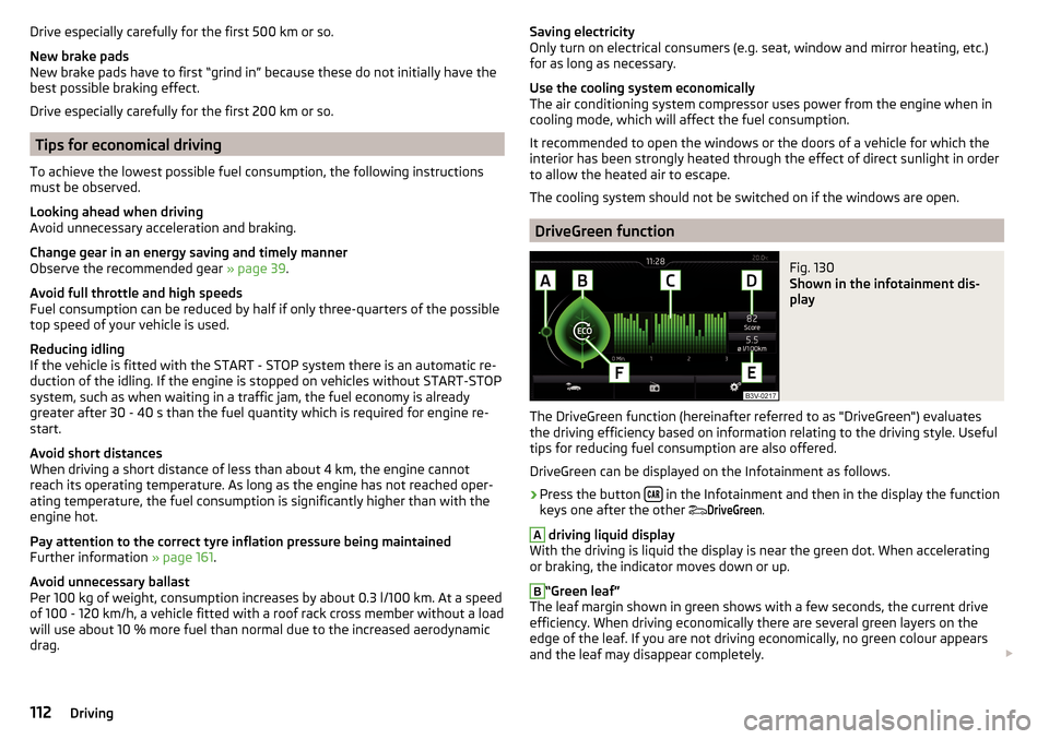
The DriveGreen function (hereinafter referred to as "DriveGreen") evaluates
the driving efficiency based on information relating to the driving style. Useful
tips for reducing fuel consumption are also offered.
DriveGreen can be displayed on the Infotainment as follows.
›
Press the button in the Infotainment and then in the display the function
keys one after the other
DriveGreen
.
A
driving liquid display
With the driving is liquid the display is near the green dot. When accelerating
or braking, the indicator moves down or up.
B
“Green leaf”
The leaf margin shown in green shows with a few seconds, the current drive
efficiency. When driving economically there are several green layers on the
edge of the leaf. If you are not driving economically, no green colour appears
and the leaf may disappear completely.
112Driving
Page 128 of 220
An audible signal is also emitted.
Tyre pressure monitoring
Introduction
This chapter contains information on the following subjects:
Save tyre pressure values
126
Save tyre pressure values and infotainment display
126
Save tyre pressure values by pressing a button
127
The tyre pressure monitoring function (hereinafter known as "system") moni-
tors the tyre pressure while driving.
When changing the tyre inflation pressure, the warning light illuminates in
the instrument cluster and an audible signal is heard.
Information on the procedure for the indication of change in tyre pressure val-
ues » page 34 .
The system can only function properly if the tyres have the prescribed tyre
pressure and this pressure values are stored in the system.
WARNING■ The general information relating to the use of assistance systems must
be observed » page 114, in section Introduction .■
The correct tyre pressure values is always the driver's responsibility. The
tyre pressure should be checked regularly » page 161.
■
The system cannot warn in case of very rapid loss of tyre pressure, e.g. in
the event of a sudden puncture.
Save tyre pressure values
Read and observe
on page 126 first.
The tyre pressure valuesare always stored in the system, if one of the follow-ing events is present. ▶ Change of tyre pressure values.
▶ Change one or more wheels.
▶ Change in position of a wheel on the vehicle.
▶ The warning light in the instrument cluster.
The storage of the tyre pressure values depends on equipment, either in the
infotainment or by pressing a button.WARNINGBefore storing the tyre pressures they must be inflated to the specified in-
flation pressure » page 161. If incorrect pressure values are storedthe sys-
tem may not warn even with a tyre pressure that is too low.
CAUTION
The tyre pressure values should be stored every 10 000 km or once a year to
ensure proper system function.
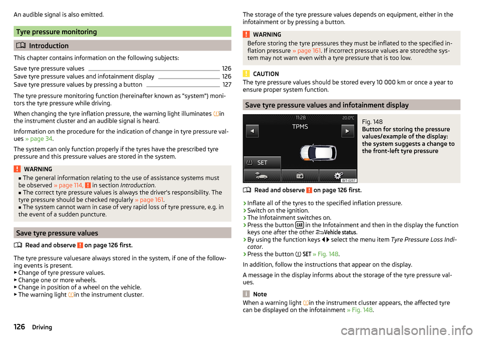
Save tyre pressure values and infotainment display
Fig. 148
Button for storing the pressure
values/example of the display:
the system suggests a change to
the front-left tyre pressure
Read and observe on page 126 first.
›
Inflate all of the tyres to the specified inflation pressure.
›
Switch on the ignition.
›
The Infotainment switches on.
›
Press the button in the Infotainment and then in the display the function
keys one after the other
Vehicle status
.
›
By using the function keys
select the menu item Tyre Pressure Loss Indi-
cator .
›
Press the button
SET
» Fig. 148 .
In addition, follow the instructions that appear on the display.
A message in the display informs about the storage of the tyre pressure val-
ues.
Note
When a warning light in the instrument cluster appears, the affected tyre
can be displayed on the infotainment » Fig. 148.126Driving
Page 129 of 220
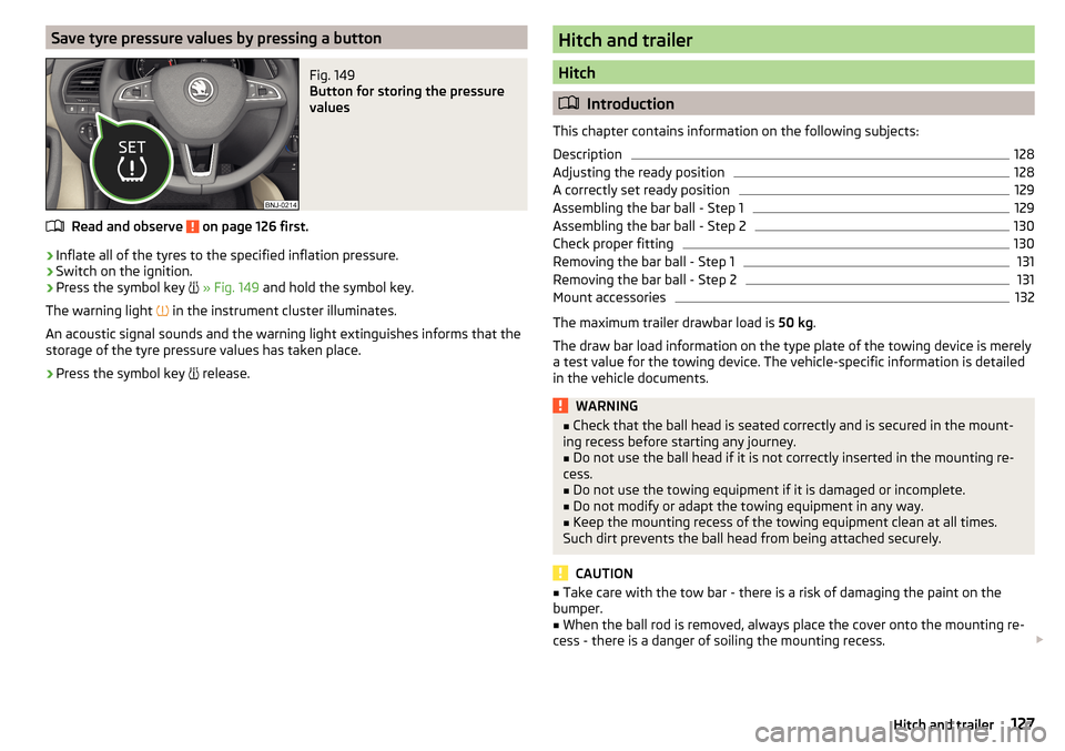
Save tyre pressure values by pressing a buttonFig. 149
Button for storing the pressure
values
Read and observe on page 126 first.
›
Inflate all of the tyres to the specified inflation pressure.
›
Switch on the ignition.
›
Press the symbol key
» Fig. 149 and hold the symbol key.
The warning light in the instrument cluster illuminates.
An acoustic signal sounds and the warning light extinguishes informs that the
storage of the tyre pressure values has taken place.
›
Press the symbol key release.
Hitch and trailer
Hitch
Introduction
This chapter contains information on the following subjects:
Description
128
Adjusting the ready position
128
A correctly set ready position
129
Assembling the bar ball - Step 1
129
Assembling the bar ball - Step 2
130
Check proper fitting
130
Removing the bar ball - Step 1
131
Removing the bar ball - Step 2
131
Mount accessories
132
The maximum trailer drawbar load is 50 kg.
The draw bar load information on the type plate of the towing device is merely
a test value for the towing device. The vehicle-specific information is detailed
in the vehicle documents.
WARNING■ Check that the ball head is seated correctly and is secured in the mount-
ing recess before starting any journey.■
Do not use the ball head if it is not correctly inserted in the mounting re-
cess.
■
Do not use the towing equipment if it is damaged or incomplete.
■
Do not modify or adapt the towing equipment in any way.
■
Keep the mounting recess of the towing equipment clean at all times.
Such dirt prevents the ball head from being attached securely.
CAUTION
■ Take care with the tow bar - there is a risk of damaging the paint on the
bumper.■
When the ball rod is removed, always place the cover onto the mounting re-
cess - there is a danger of soiling the mounting recess.
127Hitch and trailer
Page 135 of 220
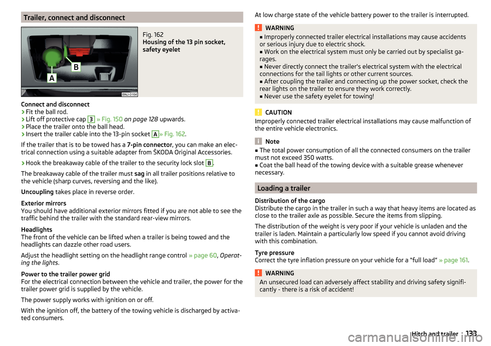
Trailer, connect and disconnectFig. 162
Housing of the 13 pin socket,
safety eyelet
Connect and disconnect
›
Fit the ball rod.
›
Lift off protective cap
3
» Fig. 150 on page 128 upwards.
›
Place the trailer onto the ball head.
›
Insert the trailer cable into the 13-pin socket
A
» Fig. 162.
If the trailer that is to be towed has a 7-pin connector, you can make an elec-
trical connection using a suitable adapter from ŠKODA Original Accessories.
›
Hook the breakaway cable of the trailer to the security lock slot
B
.
The breakaway cable of the trailer must sag in all trailer positions relative to
the vehicle (sharp curves, reversing and the like).
Uncoupling takes place in reverse order.
Exterior mirrors
You should have additional exterior mirrors fitted if you are not able to see the
traffic behind the trailer with the standard rear-view mirrors.
Headlights
The front of the vehicle can be lifted when a trailer is being towed and the
headlights can dazzle other road users.
Adjust the headlight setting on the headlight range control » page 60, Operat-
ing the lights .
Power to the trailer power grid
For the electrical connection between the vehicle and trailer, the power for the
trailer power grid is supplied by the vehicle.
The power supply works with ignition on or off.
With the ignition off, the battery of the towing vehicle is discharged by activa- ted consumers.
At low charge state of the vehicle battery power to the trailer is interrupted.WARNING■ Improperly connected trailer electrical installations may cause accidents
or serious injury due to electric shock.■
Work on the electrical system must only be carried out by specialist ga-
rages.
■
Never directly connect the trailer's electrical system with the electrical
connections for the tail lights or other current sources.
■
After coupling the trailer and connecting up the power socket, check the
rear lights on the trailer to ensure they work correctly.
■
Never use the safety eyelet for towing!
CAUTION
Improperly connected trailer electrical installations may cause malfunction of
the entire vehicle electronics.
Note
■ The total power consumption of all the connected consumers on the trailer
must not exceed 350 watts.■
Coat the ball head of the towing device with a suitable grease whenever
necessary.
Loading a trailer
Distribution of the cargo
Distribute the cargo in the trailer in such a way that heavy items are located as
close to the trailer axle as possible. Secure the items from slipping.
The distribution of the weight is very poor if your vehicle is unladen and the
trailer is laden. Maintain a particularly low speed if you cannot avoid driving
with this combination.
Tyre pressure
Correct the tyre inflation pressure on your vehicle for a “full load” » page 161.
WARNINGAn unsecured load can adversely affect stability and driving safety signifi-
cantly - there is a risk of accident!133Hitch and trailer
Page 163 of 220
Always store wheels or tyres in a cool, dry and, where possible, dark place.
Tyres which are not fixed to a wheel trim should be stored upright.
Tyre age
Tyres age losing their original characteristics, even if they are not used. The
service life of the tyres is 6 years. Therefore, we recommend not using tyres
older than 6 years.
Wheel bolts
Wheels and wheel bolts are matched to each other in terms of design. There-
fore we recommend that you use wheel rims and wheel bolts from ŠKODA
Original Accessories.WARNINGNever use tyres if you do not know anything about the condition and age.
Tyre pressure
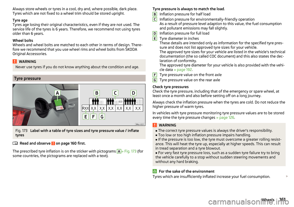
Fig. 173
Label with a table of tyre sizes and tyre pressure value / inflate
tyres
Read and observe
on page 160 first.
The prescribed tyre inflation is on the sticker with pictograms
A
» Fig. 173 (for
some countries, the pictograms are replaced with a text).
Tyre pressure is always to match the load .
Inflation pressure for half load
Inflation pressure for environmentally-friendly operation
As a result of pressure level adaption to this value, the fuel consumption
and pollutant emissions may fall slightly.
Inflation pressure for full load
Tyre diameter in inches
These details are intended only as information for the specified tyre pres-
sure and does not list approved tyre sizes for your vehicle.
The approved tyre sizes for your vehicle are listed in the vehicle's technical
documentation (the so called COC document) and this also states the dec-
laration of conformity.
The approved tyre diameter for your vehicle is also provided with the vehi-
cle data » page 192 .
Tyre pressure value on the front axle
Tyre pressure value on the rear axle
Check tyre pressures
Check the tyre pressure, including that of the emergency or spare wheel, at
least once a month and also before setting off on a long journey.
Always check the inflation pressure when the tyres are cold. Do not reduce the
higher pressure of warm tyres.
In vehicles with tyre pressure monitoring tyre pressure values are to be stored
every time the tyre pressure changes » page 126.WARNING■
The correct tyre pressure values is always the driver's responsibility.■Too low or too high inflation pressure impairs handling.■
If the pressure is too low, the tyre must overcome a greater rolling resist-
ance. This will heat the tyre up, especially at higher speeds. This can result
in tread separation and a tyre blowout.
■
For very fast tyre pressure loss, such as a sudden tyre failure try to bring
the vehicle carefully to a stop without sudden steering movements and
without any hard braking.
For the sake of the environment
Tyres which are insufficiently inflated increase your fuel consumption. BCDEFG161Wheels
Page 165 of 220
Tyre damageRead and observe
on page 160 first.
We recommend checking your tyres and wheel rims for damage (punctures,
cuts, splits and bulges, etc.) on a regular basis.
Remove any foreign objects in the tyre tread immediately (e.g. small stones).
Foreign bodies which have penetrated into the tyre (e.g. screws or nails)
should not be removed and seek help from a specialist garage.
WARNINGNever drive with damaged tyres – there is the risk of an accident.
CAUTION
The tyres must be protected from contact with substances such as oil, grease
and fuel, which could damage them. If the tyres with these substances come
into contact, then we recommend that you check this in a specialist workshop.
Unidirectional tyres
Read and observe
on page 160 first.
The direction of rotation of the tyres is marked by arrows on the wall of the
tyre .
The direction of rotation indicated must be complied with to obtain the best
benefits from the characteristics of these tyres.
These characteristics are principally the following.
▶ Increased driving stability.
▶ Reduced risk of aquaplaning.
▶ Reduced tyre noise and reduced tyre wear.
Spare wheel
Read and observe
on page 160 first.
The size of the spare wheel is identical to that of the vehicle factory installedwheels.
After changing the spare wheel, the tyre pressure should be adjusted.
In vehicles with tyre pressure monitoring, save tyre pressure values » page 126.
WARNING■
If, you get a puncture and a spare tyre has to be mounted with opposite
direction of rotation, then drive carefully. In this situation the best proper-
ties of the tyre are no longer present.■
If the dimensions or design of the spare wheel differ from the tyres fitted
to the vehicle (e.g. winter tyres or low-profile tyres), it must only be used
briefly in the event of a puncture and if an appropriately cautious style of
driving is adopted.
■
Never use the temporary spare wheel if it is damaged.
Spare wheel
Read and observe
on page 160 first.
A yellow warning label is always displayed on the rim of the temporary spare
wheel.
Please note the following if you intend to use the temporary spare wheel. ▶ The warning label must not be covered after installing the wheel.
▶ Be specially attentive when driving.
▶ The temporary spare wheel is inflated to the maximum inflation pressure for
the vehicle » page 161.
▶ Only use the temporary spare wheel to reach the nearest specialist garage
since it is not intended for permanent use.
If you need to use a spare wheel, make sure to fit a standard wheel of the ap-
propriate dimensions and design as soon as possible.
In vehicles with tyre pressure monitoring, save tyre pressure values » page 126.
WARNING■
Never drive with more than one spare wheel mounted!■Only use the spare wheel while absolutely necessary.■
Avoid accelerating at full throttle, sharp braking and fast cornering.
■
The snow chains cannot be used on the spare wheel.
■
If the dimensions or design of the temporary spare wheel differ from the
tyres fitted, never drive faster than 80 km/h (or 50 mph).
■
Never use the emergency spare wheel if it is damaged.
■
Observe the instructions on the warning sign of the temporary spare
wheel.
163Wheels
Page 174 of 220
Sealing and inflating the tyre173Notes for driving with tyre repaired173
Use the breakdown kit to reliably repair tyre damage caused by foreign bodies
or a puncture with diameters up to approx. 4 mm.
A repair made using the breakdown kit is never intended to replace a perma-
nent repair on the tyre. Its purpose is to get you to the nearest specialist ga-
rage.
The wheel need not be removed during the repair.
Do not remove foreign bodies that have penetrated the wheel profile from
the tyre (e.g. screws or nails).
Immediately replace the wheel that was repaired using the breakdown kit or
consult a specialist garage about repair possibilities.
WARNING■ The sealant is hazardous to heath. Remove immediately if it comes into
contact with the skin.■
Observe the manufacturer's usage instructions for the breakdown kit.
Note
A new bottle of sealant can be purchased from ŠKODA Original Parts.
Components of the puncture repair kit
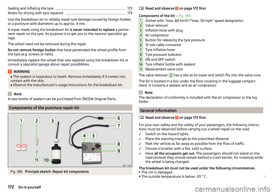
Fig. 186
Principle sketch: Repair kit components
Read and observe on page 172 first.
Components of the kit » Fig. 186
Sticker with “max. 80 km/h”/“max. 50 mph” speed designation
Valve remover
Inflation hose with plug
Air compressor
Button for releasing the tyre pressure
12 volt cable connector
Tyre inflation hose
Tyre pressure indicator
ON and OFF switch
Tyre inflator bottle with sealant
Replacement valve core
The valve remover
2
has a slot at its lower end which fits into the valve core.
The kit is located in a box under the floor covering in the luggage compart-
ment. It contains a sealant and an air compressor.
Note
The declaration of conformity is included with the air compressor or the log
folder.
General information
Read and observe
on page 172 first.
For your own safety and the safety of your passengers, the following instruc-
tions must be observed before carrying out a wheel repair on the road.
Switch on the hazard lights.
Place the warning triangle at the prescribed distance.
Park the vehicle as far away as possible from the flow of traffic.
Choose a location with a flat, solid surface.
Have all the occupants get out. The passengers should not stand on the
road (instead they should remain behind a crash barrier, for instance) while
the wheel is being changed.
The breakdown kit must not be used under the following circumstances. ▶ The rim is damaged.
▶ The outside temperature is below -20 ° C.
1234567891011172Do-it-yourself
Page 175 of 220
▶The cut or puncture is larger than 4 mm.
▶ The tyre wall is damaged.
▶ After the expiration date (see inflation bottle).
Preparations for using the breakdown kit
Read and observe
on page 172 first.
The following preparatory work must be carried out before using the break-
down kit.
›
Switch off the engine.
›
On vehicles with Manual transmission select 1st gear .
›
On vehicles with automatic transmission place the selector lever in the P po-
sition.
›
Firmly apply the handbrake.
›
Check that you can carry out the repairs with the breakdown kit » page 172,
General information .
›
Uncouple trailer, if attached.
›
Remove the breakdown kit from the boot.
›
Stick the corresponding sticker
1
» Fig. 186 on page 172 on the dashboard in
the driver's field of view.
›
Unscrew the valve cap.
›
Use the valve remover
2
to unscrew the valve core and place it on a clean
surface (rag, paper, etc.).
Sealing and inflating the tyre
Read and observe
on page 172 first.
Sealing
›
Shake the tyre inflator bottle
10
» Fig. 186 on page 172 vigorously several
times.
›
Firmly screw the inflation hose
3
onto the tyre inflater bottle
10
. The film on
the cap is pierced automatically.
›
Remove the plug from the inflation hose
3
and push the open end fully on-
to the tyre valve.
›
Hold the bottle
10
with the bottom facing upwards and fill all of the sealing
agent from the tyre inflator bottle into the tyre.
›
Remove the filler plug from the tyre valve.
›
Screw the valve core back into the tyre valve using the valve remover
2
.
Inflating›Screw the air compressor tyre inflation hose 7 » Fig. 186 on page 172 firmly
onto the tyre valve.›
On vehicles with manual transmission , move the lever to the neutral posi-
tion.
›
On vehicles with automatic transmission place the selector lever in the P po-
sition.
›
Start the engine and run it in idle.
›
Plug the connector
6
into 12 volt socket » page 77.
›
Switch on the air compressor with the ON and OFF switch
9
.
›
Allow the air compressor to run until a pressure of 2.0 - 2.5 bar is achieved.
Maximum run time of 8 minutes » .
›
Switch off the air compressor.
›
If you cannot reach an air pressure of 2.0 - 2.5 bar, unscrew the tyre inflation
hose
7
from the tyre valve.
›
Drive the vehicle 10 metres forwards or backwards to allow the sealing agent
to “distribute” in the tyre.
›
Firmly screw the tyre inflation hose
7
back onto the tyre valve and repeat
the inflation process.
›
Switch off the air compressor.
›
Remove the tyre inflation hose
7
from the tyre valve.
Once a tyre inflation pressure of 2.0 - 2.5 bar is achieved, you can continue the journey.
WARNING■ If the tyre does not inflate to at least. 2.0 bar, the damage is too great.
The sealing agent cannot be used to seal the tyre. Do not drive the vehi-
cle! Seek help from a specialist garage.■
The tyre inflation hose and air compressor may get hot while the tyre is
being inflated – there is a risk of injury.
CAUTION
Switch off the air compressor after running 8 minutes at the most – risk of
overheating. Allow the air compressor to cool a few minutes before switching
it on again.
Notes for driving with tyre repaired
Read and observe
on page 172 first.
The filling pressure of the repaired tyre is a 10-minute test drive.
173Emergency equipment, and self-help