turn signal SKODA KODIAQ 2016 1.G Owner's Guide
[x] Cancel search | Manufacturer: SKODA, Model Year: 2016, Model line: KODIAQ, Model: SKODA KODIAQ 2016 1.GPages: 344, PDF Size: 58.96 MB
Page 144 of 344
Radio text display / image presentation (DAB) (does not apply to Infotain-
ment Swing)
Menu Settings Radio
Information symbol in the status lineSymbolMeaningTraffic signal is available Traffic signal is not available RDS function is switched off (FM) AF Alternative frequency is switched off (FM)Signal is not available (DAB)
If the displayed station name continuously changes (dynamic text), then it is
possible to fix the current text by holding your finger on the device screen in
the station name area. By holding your finger in the area of the station name
again, the station name is displayed in its entirety again.
Display DAB main menu (does not apply to Infotainment Swing)
In DAB broadcasting, the display of additional information and images (Slide- show) is possible as long as the currently tuned station is broadcasting this in-
formation.
The display variant can be selected from the menu that appears as follows. ▶ In the Radio main menu, press the function surface in the
DAB
area
.
Search stations and select frequency
Find stations
›
Tap on the function surface in the Radio main menu
or
.
Depending on the setting
Arrow buttons:
will set an available station from the
Station list or a station of the current broadcast range on the Station buttons.
Select frequency
›
To display the value of the currently chosen frequency, tap the function sur-
face in the Radio main menu
.
›
To
Set the desired frequency value in Infotainment Swing, use the slider or
the function surfaces
Use the bottom of the screen, if necessary, turn
the controller .
The frequency selection is terminated by pressing
the button.
Scan through the stations one after the other (scan)
The function scans through all the available stations in the current frequency
range in succession, for a few seconds each.›
To start/finish the automatic play of the available stations in Infotainment
Columbus, Amundsen, Bolero press the function surface in the Radio main
menu
Tap →
scan
.
›
To end autoplay, tap the function surface
.
›
To start/finish the automatic play of the available stations in Infotainment
Swing, press the controller in the Radio main menu
/ press.
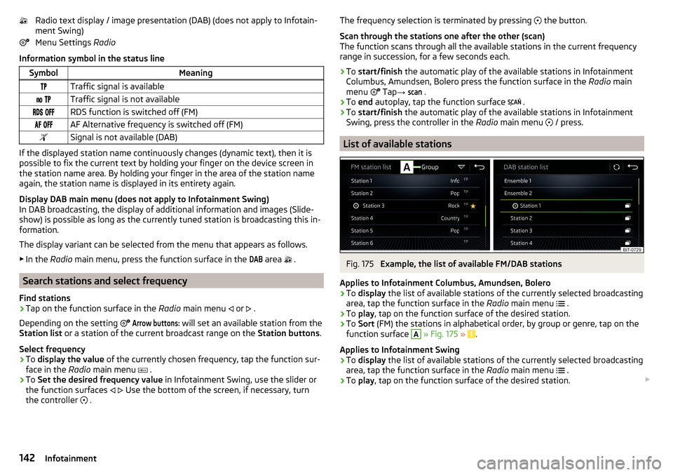
List of available stations
Fig. 175
Example, the list of available FM/DAB stations
Applies to Infotainment Columbus, Amundsen, Bolero
›
To display the list of available stations of the currently selected broadcasting
area, tap the function surface in the Radio main menu
.
›
To
play , tap on the function surface of the desired station.
›
To Sort (FM) the stations in alphabetical order, by group or genre, tap on the
function surface
A
» Fig. 175 » .
Applies to Infotainment Swing
›
To display the list of available stations of the currently selected broadcasting
area, tap the function surface in the Radio main menu
.
›
To
play , tap on the function surface of the desired station.
142Infotainment
Page 175 of 344
CAUTIONTo establish the connection, it is necessary that the date and time in Infotain-
ment are set correctly. If the date and time setting is based on the GPS signal,
then problems may arise with establishing a connection with a poor GPS signal
reception.
Note
■ During the connection process, information messages may be displayed on
the Infotainment screen, and in the phone display. These messages must be
observed and confirmed if necessary (e.g. Release of data transfer, enabling
the contact import, release of text messages).■
We recommend that you use extension cords from ŠKODA Original Accesso-
ries.
■
With some connected devices, it is necessary that the connected external
device is unlocked over the entire duration of the connection for trouble-free
functioning of the SmartLink function“”.
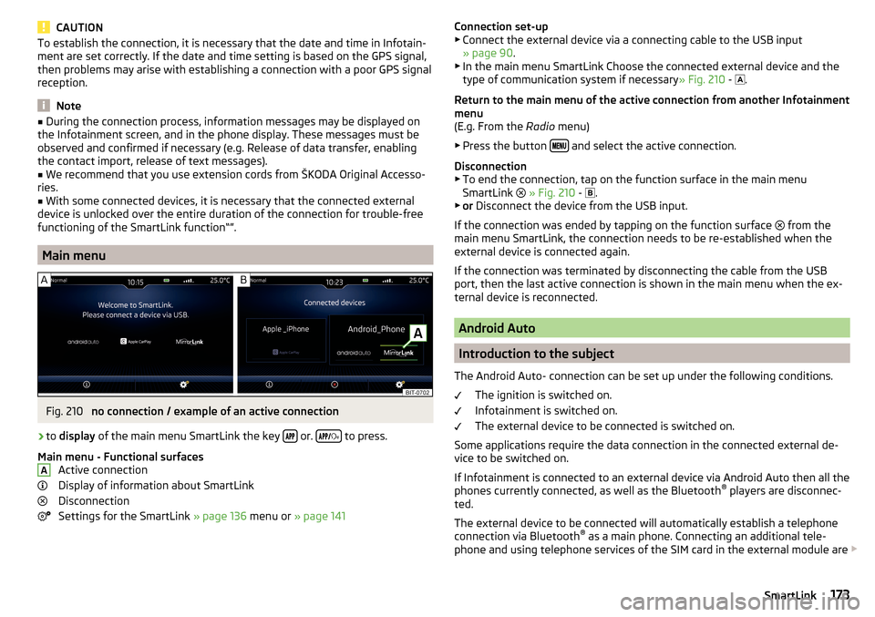
Main menu
Fig. 210
no connection / example of an active connection
›
to display of the main menu SmartLink the key or.
to press.
Main menu - Functional surfaces Active connection
Display of information about SmartLink
Disconnection
Settings for the SmartLink » page 136 menu or » page 141
AConnection set-up
▶ Connect the external device via a connecting cable to the USB input
» page 90 .
▶ In the main menu SmartLink Choose the connected external device and the
type of communication system if necessary » Fig. 210 -
.
Return to the main menu of the active connection from another Infotainment
menu
(E.g. From the Radio menu)
▶ Press the button
and select the active connection.
Disconnection ▶ To end the connection, tap on the function surface in the main menu
SmartLink
» Fig. 210 -
.
▶ or Disconnect the device from the USB input.
If the connection was ended by tapping on the function surface from the
main menu SmartLink, the connection needs to be re-established when the
external device is connected again.
If the connection was terminated by disconnecting the cable from the USB
port, then the last active connection is shown in the main menu when the ex-
ternal device is reconnected.
Android Auto
Introduction to the subject
The Android Auto- connection can be set up under the following conditions. The ignition is switched on.
Infotainment is switched on.
The external device to be connected is switched on.
Some applications require the data connection in the connected external de-
vice to be switched on.
If Infotainment is connected to an external device via Android Auto then all the
phones currently connected, as well as the Bluetooth ®
players are disconnec-
ted.
The external device to be connected will automatically establish a telephone
connection via Bluetooth ®
as a main phone. Connecting an additional tele-
phone and using telephone services of the SIM card in the external module are
173SmartLink
Page 206 of 344
Note■The engine running noises may be louder at first for a short time after start-
ing the cold engine.■
You should not switch on any major electrical components during the heat-
ing period, otherwise the vehicle battery will be drained unnecessarily.
■
After switching off the ignition, the radiator fan may intermittently continue
to run for approx. 10 minutes (also continuously).
Problems with the engine start - vehicles with starter button
Fig. 252
Engine start - hold key on button
Read and observe and on page 202 first.
If no engine start is possible and the display of the instrument cluster shows a message that the key could not be detected by the system or there is a system
fault, then try to start the engine as follows.
›
Push the starter button and then hold the key with the back of it on the but-
ton » Fig. 252 .
If the engine does not start, the help of a specialist garage is required.
CAUTION
The key may not be detected by the system if the battery in the key is running
out of charge or the signal fails (strong electromagnetic field) or is shielded
(e.g. in an aluminium case).START-STOP-System
Introduction
This chapter contains information on the following subjects:
operation
204
manually activate/deactivate system
205
The START-STOPsystem (hereinafter referred to as the system) reduces
CO 2emissions and harmful emissions, and saves fuel.
If the system determine that the engine is not needed when the vehicle stops
or is at a standstill (e.g. at the traffic lights), it turns off the engine and starts it
again when moving off.
The system function depends on many factors. Some of them are down to the
driver, while others are systemic and can neither be influenced nor identified.
For this reason, the system may react differently in situations which seem
identical from the driver's perspective.
The system is automatically activated every time the ignition is switched on
(even when it has previously been manually deactivated with the button).
Note
If the engine has stopped due to the system, the ignition remains switched on.
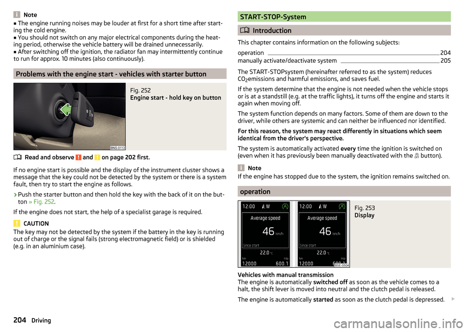
operation
Fig. 253
Display
Vehicles with manual transmission
The engine is automatically switched off as soon as the vehicle comes to a
halt, the shift lever is moved into neutral and the clutch pedal is released.
The engine is automatically started as soon as the clutch pedal is depressed.
204Driving
Page 209 of 344
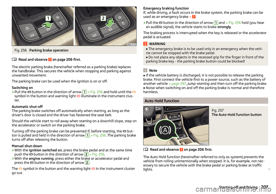
Fig. 256
Parking brake operation
Read and observe
on page 206 first.
The electric parking brake (hereinafter referred as a parking brake) replaces the handbrake. This secures the vehicle when stopping and parking against
unwanted movement.
The parking brake can be used when the ignition is on or off.
Switching on
›
Pull the button in the direction of arrow
1
» Fig. 256 and hold until the
symbol in the button and warning light illuminate in the instrument clus-
ter.
Automatic shut-off
The parking brake switches off automatically when starting, as long as the
driver's door is closed and the driver has fastened the seat belt.
Should the vehicle start to roll away when starting on a downhill slope, step on
the accelerator or switch on the parking brake.
Turning off the parking brake can be prevented if, before starting, the but-
ton is pulled and held in the direction of arrow
1
» Fig. 256 . The parking brake
turns off after releasing the button.
Manual shut-down
›
With the ignition switched on , press the brake pedal and at the same time
push the button in the direction of arrow
2
» Fig. 256 .
›
With the engine running , press either the brake or accelerator pedal and
press the button in the direction of arrow
2
.
The symbol in the button and the warning light
in the instrument cluster
go out.
Emergency braking function
If, while driving, a fault occurs in the brake system, the parking brake can be
used as an emergency brake »
.
›
Pull the
button in the direction of arrow
1
and » Fig. 256 hold (you hear
an audible signal), the vehicle starts to brake strongly.
The braking process is interrupted when the key is released or the accelerator
pedal is actuated.
WARNING■ The emergency brake is to be used only in an emergency when the vehi-
cle cannot be stopped with the brake pedal.■
Do not place any objects in the recessed grip for the finger in front of the
parking brake key - the parking brake button could be blocked!
Note
■ If the vehicle battery is discharged, it is not possible to release the parking
brake. First connect the vehicle first to a power source, such as the battery of
another vehicle » page 297, Jump-starting and then turn off the parking brake.■
Noise when switching on and off the parking brake is normal and therefore
harmless.
Auto Hold function
Fig. 257
The Auto-Hold function button
Read and observe on page 206 first.
The Auto Hold function (hereinafter referred to only as system) prevents the
vehicle from rolling unintentionally when stopped. It is, for example, not nec-
essary to secure the vehicle with the brake pedal or parking brake at traffic
lights.
207Starting-off and Driving
Page 228 of 344
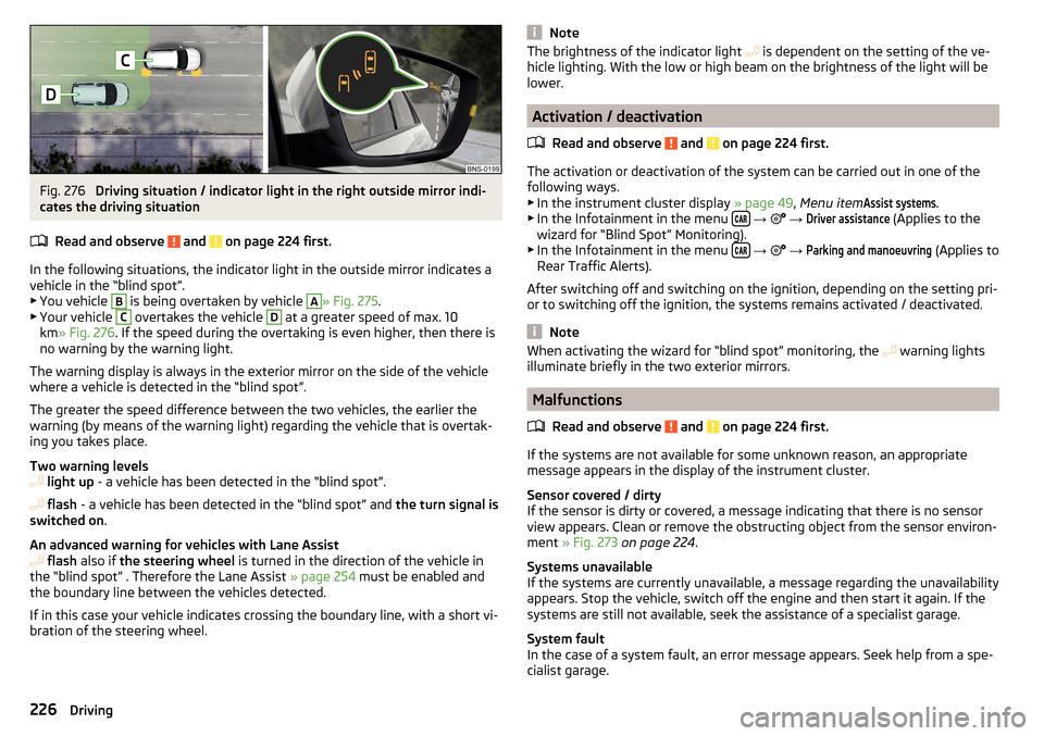
Fig. 276
Driving situation / indicator light in the right outside mirror indi-
cates the driving situation
Read and observe
and on page 224 first.
In the following situations, the indicator light in the outside mirror indicates avehicle in the “blind spot”.
▶ You vehicle
B
is being overtaken by vehicle
A
» Fig. 275 .
▶ Your vehicle
C
overtakes the vehicle
D
at a greater speed of max. 10
km » Fig. 276 . If the speed during the overtaking is even higher, then there is
no warning by the warning light.
The warning display is always in the exterior mirror on the side of the vehicle where a vehicle is detected in the “blind spot”.
The greater the speed difference between the two vehicles, the earlier the
warning (by means of the warning light) regarding the vehicle that is overtak-
ing you takes place.
Two warning levels
light up - a vehicle has been detected in the “blind spot”.
flash - a vehicle has been detected in the “blind spot” and the turn signal is
switched on .
An advanced warning for vehicles with Lane Assist
flash also if the steering wheel is turned in the direction of the vehicle in
the “blind spot” . Therefore the Lane Assist » page 254 must be enabled and
the boundary line between the vehicles detected.
If in this case your vehicle indicates crossing the boundary line, with a short vi-
bration of the steering wheel.
NoteThe brightness of the indicator light is dependent on the setting of the ve-
hicle lighting. With the low or high beam on the brightness of the light will be
lower.
Activation / deactivation
Read and observe
and on page 224 first.
The activation or deactivation of the system can be carried out in one of the
following ways. ▶ In the instrument cluster display » page 49, Menu item
Assist systems
.
▶ In the Infotainment in the menu
→
→
Driver assistance
(Applies to the
wizard for “Blind Spot” Monitoring).
▶ In the Infotainment in the menu
→
→
Parking and manoeuvring
(Applies to
Rear Traffic Alerts).
After switching off and switching on the ignition, depending on the setting pri-
or to switching off the ignition, the systems remains activated / deactivated.
Note
When activating the wizard for “blind spot” monitoring, the warning lights
illuminate briefly in the two exterior mirrors.
Malfunctions
Read and observe
and on page 224 first.
If the systems are not available for some unknown reason, an appropriate
message appears in the display of the instrument cluster.
Sensor covered / dirty
If the sensor is dirty or covered, a message indicating that there is no sensor
view appears. Clean or remove the obstructing object from the sensor environ-
ment » Fig. 273 on page 224 .
Systems unavailable
If the systems are currently unavailable, a message regarding the unavailability
appears. Stop the vehicle, switch off the engine and then start it again. If the
systems are still not available, seek the assistance of a specialist garage.
System fault
In the case of a system fault, an error message appears. Seek help from a spe-
cialist garage.
226Driving
Page 237 of 344
Activation/deactivation
The system can be activated/deactivated by pressing the button » Fig. 289 .
When the system is activated, the symbol illuminates in the button.
Search for parking space
Read and observe
and on page 234 first.
The system searches for a parking space in a number of parallel and transverse
parked vehicles on the passenger or driver's side.
Process with the parking space search
›
Slowly drive past a row of parked vehicles.
›
Activate the system with the button
» Fig. 289 on page 234 .
The system will automatically search for a parking space on the passenger
side.
If the system finds a parking space, the recommended parking mode is dis-
played » Fig. 291 on page 235
or
» Fig. 292 on page 236 -
.
Activate the turn signal on the driver's side if you wish to look for a parking
space on this side of the road. The display changes and the system searches
for a parking space on the driver's side.
Note
If the symbol (km / h) is shown in the display while you are looking for a
parking space, the vehicle speed should be reduced below 40 km / hr (parallel parking) or below 20 km / hr (Transverse parking).
Switch to park mode
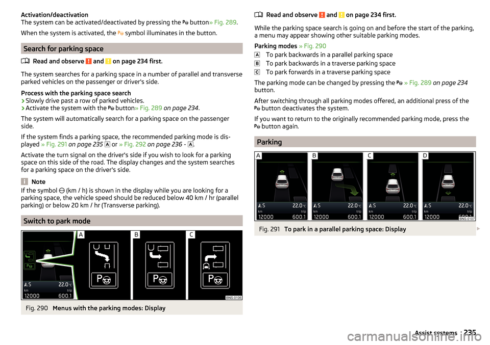
Fig. 290
Menus with the parking modes: Display
Read and observe and on page 234 first.
While the parking space search is going on and before the start of the parking,a menu may appear showing other suitable parking modes.
Parking modes » Fig. 290
To park backwards in a parallel parking space
To park backwards in a traverse parking space
To park forwards in a traverse parking space
The parking mode can be changed by pressing the
» Fig. 289 on page 234
button.
After switching through all parking modes offered, an additional press of the
button deactivates the system.
If you want to return to the originally recommended parking mode, press the
button again.
Parking
Fig. 291
To park in a parallel parking space: Display
235Assist systems
Page 239 of 344
Leaving a parallel parking spaceRead and observe
and on page 234 first.
The system supports the driver when leaving a parking space of a parallel
parking space.
Leaving a parking space process
›
Press the
» Fig. 289 on page 234 button.
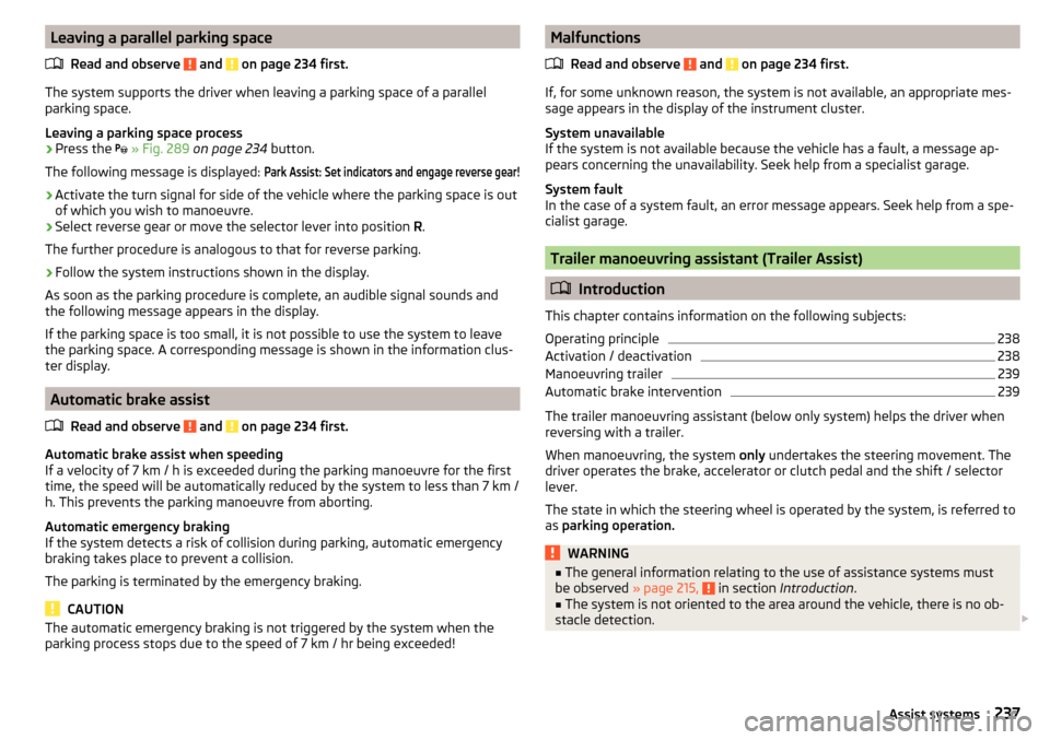
The following message is displayed:
Park Assist: Set indicators and engage reverse gear!›
Activate the turn signal for side of the vehicle where the parking space is out
of which you wish to manoeuvre.
›
Select reverse gear or move the selector lever into position R.
The further procedure is analogous to that for reverse parking.
›
Follow the system instructions shown in the display.
As soon as the parking procedure is complete, an audible signal sounds and
the following message appears in the display.
If the parking space is too small, it is not possible to use the system to leave
the parking space. A corresponding message is shown in the information clus-
ter display.
Automatic brake assist
Read and observe
and on page 234 first.
Automatic brake assist when speeding
If a velocity of 7 km / h is exceeded during the parking manoeuvre for the first
time, the speed will be automatically reduced by the system to less than 7 km /
h. This prevents the parking manoeuvre from aborting.
Automatic emergency braking
If the system detects a risk of collision during parking, automatic emergency
braking takes place to prevent a collision.
The parking is terminated by the emergency braking.
CAUTION
The automatic emergency braking is not triggered by the system when the
parking process stops due to the speed of 7 km / hr being exceeded!Malfunctions
Read and observe
and on page 234 first.
If, for some unknown reason, the system is not available, an appropriate mes-
sage appears in the display of the instrument cluster.
System unavailable
If the system is not available because the vehicle has a fault, a message ap-
pears concerning the unavailability. Seek help from a specialist garage.
System fault
In the case of a system fault, an error message appears. Seek help from a spe-
cialist garage.
Trailer manoeuvring assistant (Trailer Assist)
Introduction
This chapter contains information on the following subjects:
Operating principle
238
Activation / deactivation
238
Manoeuvring trailer
239
Automatic brake intervention
239
The trailer manoeuvring assistant (below only system) helps the driver when
reversing with a trailer.
When manoeuvring, the system only undertakes the steering movement. The
driver operates the brake, accelerator or clutch pedal and the shift / selector
lever.
The state in which the steering wheel is operated by the system, is referred to
as parking operation.
WARNING■
The general information relating to the use of assistance systems must
be observed » page 215, in section Introduction .■
The system is not oriented to the area around the vehicle, there is no ob-
stacle detection.
237Assist systems
Page 249 of 344
›Using the switch
on the lever, adjust the line 2 to the desired dis-
tance.
Note
■ If the proximity is changed in infotainment, the change will only come into
effect after a subsequent activation of the ACC.■
The higher the speed, the greater the proximity to the vehicle ahead.
■
The adjustment of the distance is stored (depending on Infotainment type) in
the active user account personalisation » page 50.
Special driving conditions
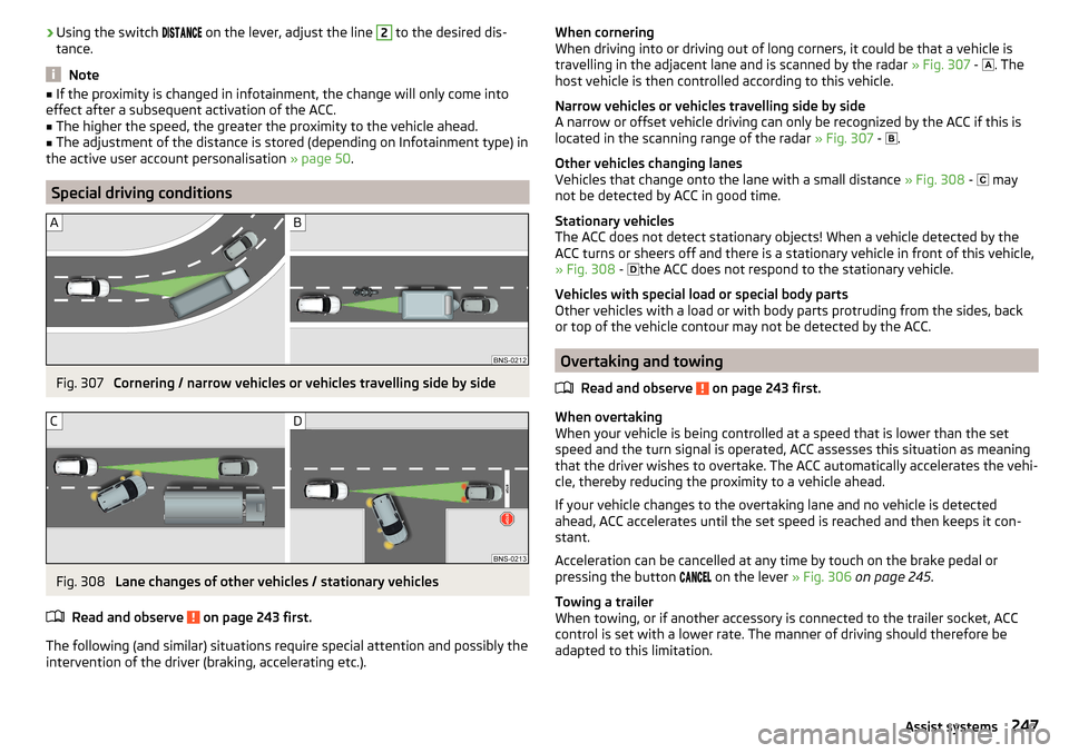
Fig. 307
Cornering / narrow vehicles or vehicles travelling side by side
Fig. 308
Lane changes of other vehicles / stationary vehicles
Read and observe
on page 243 first.
The following (and similar) situations require special attention and possibly the
intervention of the driver (braking, accelerating etc.).
When cornering
When driving into or driving out of long corners, it could be that a vehicle is
travelling in the adjacent lane and is scanned by the radar » Fig. 307 -
. The
host vehicle is then controlled according to this vehicle.
Narrow vehicles or vehicles travelling side by side
A narrow or offset vehicle driving can only be recognized by the ACC if this is
located in the scanning range of the radar » Fig. 307 -
.
Other vehicles changing lanes
Vehicles that change onto the lane with a small distance » Fig. 308 -
may
not be detected by ACC in good time.
Stationary vehicles
The ACC does not detect stationary objects! When a vehicle detected by the
ACC turns or sheers off and there is a stationary vehicle in front of this vehicle,
» Fig. 308 -
the ACC does not respond to the stationary vehicle.
Vehicles with special load or special body parts
Other vehicles with a load or with body parts protruding from the sides, back
or top of the vehicle contour may not be detected by the ACC.
Overtaking and towing
Read and observe
on page 243 first.
When overtaking
When your vehicle is being controlled at a speed that is lower than the set
speed and the turn signal is operated, ACC assesses this situation as meaning
that the driver wishes to overtake. The ACC automatically accelerates the vehi-
cle, thereby reducing the proximity to a vehicle ahead.
If your vehicle changes to the overtaking lane and no vehicle is detected
ahead, ACC accelerates until the set speed is reached and then keeps it con-
stant.
Acceleration can be cancelled at any time by touch on the brake pedal or
pressing the button on the lever
» Fig. 306 on page 245 .
Towing a trailer
When towing, or if another accessory is connected to the trailer socket, ACC
control is set with a lower rate. The manner of driving should therefore be
adapted to this limitation.
247Assist systems
Page 257 of 344
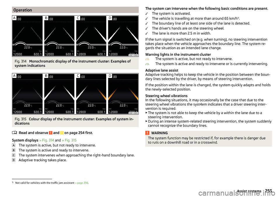
OperationFig. 314
Monochromatic display of the instrument cluster: Examples of
system indications
Fig. 315
Colour display of the instrument cluster: Examples of system in-
dications
Read and observe
and on page 254 first.
System displays » Fig. 314 and » Fig. 315
The system is active, but not ready to intervene.
The system is active and ready to intervene.
The system intervenes when approaching the right-hand boundary lane.
Adaptive tracking takes place.
The system can intervene when the following basic conditions are present. The system is activated.
The vehicle is travelling at more than around 65 km/h 1)
.
The boundary line of at least one side of the lane is detected.
The driver's hands are on the steering wheel.
The lane is more than 2.5 m in width.
If the turn signal is switched on (e.g. when turning), no steering intervention takes place when the vehicle approaches the boundary line. The system re-
gards the situation as an intended lane change.
Warning lights in the instrument cluster The system is active, but not ready to intervene.
The system is active and ready to intervene or is currently intervening.
Adaptive lane assist
Adaptive tracking helps to keep the vehicle in the position between the boun-
dary lines selected by the driver, by means of steering intervention.
If the position within the lane is changed, the system quickly adapts and holds
the newly-selected position.
Steering wheel vibrations
In the following situations, it may occasionally be the case that due to the
steering wheel vibrations the syst4em indicates that a driver steering inter-
vention is required.
▶ The system is not able to keep the vehicle by a within the lane due to a
steering intervention.
▶ During an intense system-related steering intervention, the system suddenly
cannot recognize the boundary lines.WARNINGThe system function may be restricted if, for example there is danger due
to ruts on a downhill road or in a crosswind.1)
Not valid for vehicles with the traffic jam assistant » page 256.
255Assist systems
Page 262 of 344
WARNING■Please take note of the general points relating to the use of assistance
systems » page 215, in section Introduction .■
For the driving ability is always the driver's responsibility. Never drive if
you feel tired.
■
The system may not detect all cases where a break is needed.
■
Therefore, take regular, sufficient breaks during long trips.
■
There will be no system warning during the so-called micro-sleep.
Note
■ In some situations, the system may evaluate the driving incorrectly and thus
mistakenly recommend a break (e.g. sporty driving, adverse weather condi-
tions or poor road conditions).■
The system is designed primarily for use on motorways.
Tyre pressure monitoring
Introduction
This chapter contains information on the following subjects:
Storing the tyre pressure values and Infotainment display
260
The tyre pressure monitoring function (following known as system) monitors
the tyre pressure while driving.
If the tyre inflation pressure changes, the warning light
lights up in the in-
strument cluster and an audible signal sounds » page 37.
The system can only function properly if the tyres have the prescribed inflation
pressure and these pressure values are stored in the system.
Always save the tyre pressure values in the system if one of the following
events occurs.
▶ Change of tyre pressure values.
▶ Change one or more wheels.
▶ Change in position of a wheel on the vehicle.
▶ The warning light
in the instrument cluster.
WARNING■
Please take note of the general points relating to the use of assistance
systems » page 215, in section Introduction .■
Having the correct tyre inflation pressure is always the driver's responsi-
bility. Tyre pressure should be checked regularly » page 286.
■
The system cannot warn in case of very rapid tyre inflation pressure loss,
e.g. in case of sudden tyre damage.
■
Before storing the pressures, the tyres must be inflated to the specified
inflation pressure » page 286. If the wrong pressure valuesare stored, the
system may not issue any warnings, even if the tyre pressure is too low.
CAUTION
To ensure proper system function, the tyre pressure values must be stored ev-
ery 10,000 km or 1x a year.
Storing the tyre pressure values and Infotainment display
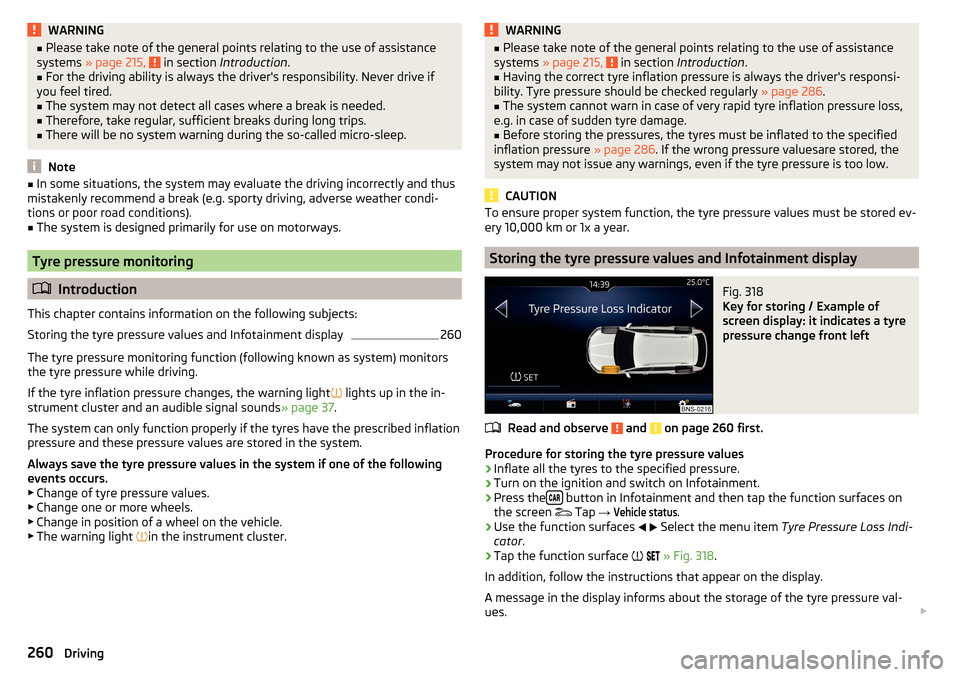
Fig. 318
Key for storing / Example of
screen display: it indicates a tyre
pressure change front left
Read and observe and on page 260 first.
Procedure for storing the tyre pressure values
›
Inflate all the tyres to the specified pressure.
›
Turn on the ignition and switch on Infotainment.
›
Press the button in Infotainment and then tap the function surfaces on
the screen Tap
→
Vehicle status
.
›
Use the function surfaces
Select the menu item
Tyre Pressure Loss Indi-
cator .
›
Tap the function surface
» Fig. 318 .
In addition, follow the instructions that appear on the display.
A message in the display informs about the storage of the tyre pressure val-
ues.
260Driving