Jump start SKODA KODIAQ 2016 1.G Owner's Manual
[x] Cancel search | Manufacturer: SKODA, Model Year: 2016, Model line: KODIAQ, Model: SKODA KODIAQ 2016 1.GPages: 344, PDF Size: 58.96 MB
Page 6 of 344
Do-it-yourself
Emergency equipment and self-help290
Emergency equipment
290
Changing a wheel
291
Puncture repair kit
295
Jump-starting
297
Towing the vehicle
298
Remote control and removable light -
replacing the battery/batteries
300
Emergency unlocking / locking of doors
302
Replacing windscreen wiper blades
303
Fuses and light bulbs
305
Fuses
305
Bulbs
308
Technical data
Technical data
313
Basic vehicle data
313
Vehicle-specific details per engine type
318
Index
4Table of Contents
Page 149 of 344
CAUTION■Do not save any important data or that which has not been backed up on the
connected audio sources. ŠKODA assumes no responsibility for lost or dam-
aged files or connected audio sources.■
When changing or connecting an audio source, this may cause sudden
changes in volume. Reduce the volume before changing or connecting an au-
dio source.
■
When connecting an external audio source, the external source information
messages can be displayed. These messages must be observed and if neces-
sary confirmed (e.g. enabling data transfer etc).
Note
The national copyright laws that apply in your country must be observed.
CD / DVD
Only valid for Infotainment Columbus.
Fig. 180
CD / DVD case
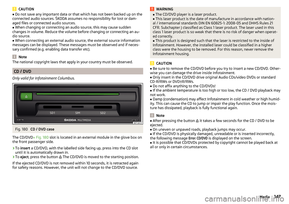
The CD/DVD » Fig. 180 slot is located in an external module in the glove box on
the front passenger side.
›
To insert a CD/DVD, with the labelled side facing up, press into the CD slot
until it is automatically drawn in.
›
To eject , press the button
The CD/DVD is moved to the starting position.
If the ejected CD/DVD is not removed within 10 seconds, it is retracted again
for safety reasons. However, the unit will not change to the CD/DVD source.
WARNING■ The CD/DVD player is a laser product.■This laser product is the date of manufacture in accordance with nation-
al / international standards DIN EN 60825-1: 2008-05 and DHHS Rules 21
CFR. Subchapter J classified as Class 1 laser product. The laser used in this
class 1 laser product is so weak that there is no risk of danger when operat-
ed correctly.■
This product is designed such that the laser is restricted to the inside of
Infotainment. However, the installed laser could be classified in a higher
class were the housing to be removed. For this reason, never remove the
Infotainment housing.
CAUTION
■ Be sure to remove the CD/DVD before you try to insert a new CD/DVD. Other-
wise you can damage the drive inside Infotainment.■
Only insert in the CD/DVD drive original Audio CDs/video DVDs or standard
CD-R/RWs or DVD±R/RWs.
■
Do not affix anything to the CD/DVDs!
■
If the ambient temperature is too high or too low, the CD / DVD playback may
not work.
■
Damp (condensation) may affect Infotainment in cold weather or high humid-
ity. This can cause the CD to jump or impair the play function. Once the mois-
ture has dissipated, playback is fully functional again.
Note
■ After pressing the button it takes a few seconds for the CD / DVD to be
ejected.■
On uneven or unpaved roads, playback jumps may occur.
■
If the CD/DVD is physically damaged, unreadable or is inserted incorrectly,
the following message
Error: CD/DVD
is displayed on the screen.
■
It is possible that CD/DVDs protected by copyright cannot be played back at
all or only in certain circumstances.
147Media
Page 150 of 344
SD cardFig. 181
Infotainment Columbus, Amund-
sen, Bolero: insert SD card
Fig. 182
Infotainment Swing: insert SD
card
›
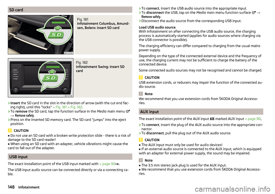
Insert the SD card in the slot in the direction of arrow (with the cut end fac-
ing right), until this “locks” » Fig. 181 » Fig. 182 .
›
To remove the SD card, tap the function surface in the Media main menu
→
Remove safely
.
›
Press on the inserted SD memory card. The SD card “jumps” into the eject
position.
CAUTION
■ Do not use an SD card with a broken write protection slide - there is a risk of
damage to the SD card reader!■
When using an SD card with an adapter, vehicle vibrations might cause the
card to fall out of the adapter.
USB input
The exact installation point of the USB input marked with » page 90
.
The USB input audio source can be connected directly or via a connecting ca-
ble.
› To
connect , insert the USB audio source into the appropriate input.›To disconnect the USB, tap on the Media main menu function surface →
Remove safely
.
›
Disconnect the audio source from the corresponding USB input.
Load USB audio source
With Infotainment on after connecting the USB audio source, the charging
process is automatically started (applies for audio sources where charging via
the USB connector is possible).
The charging efficiency can differ compared to charging from the usual mains
power supply.
Depending on the type of the connected external device and the frequency of
use, the charging current may not be sufficient to charge the battery of the
connected device.
Some connected audio sources may not be recognised and cannot be charged.
CAUTION
USB extension cords, or reducers may impair the function of the connected au-
dio source.
Note
We recommend that you use extension cords from ŠKODA Original Accesso-
ries.
AUX input
The exact installation point of the AUX input
marked AUX input » page 90,
›
To connect , insert the plug of the AUX audio source into the appropriate con-
nector.
›
To disconnect , pull the plug out of the AUX audio source.
CAUTION
■
The AUX input must only be used for audio devices!■If an external audio source is connected to the AUX input, which is equipped
with an adapter for external power supply, the sound may be impaired.
Note
■ The 3.5 mm stereo jack plug is used for the AUX input.■We recommend that you use extension cords from ŠKODA Original Accesso-
ries.148Infotainment
Page 209 of 344
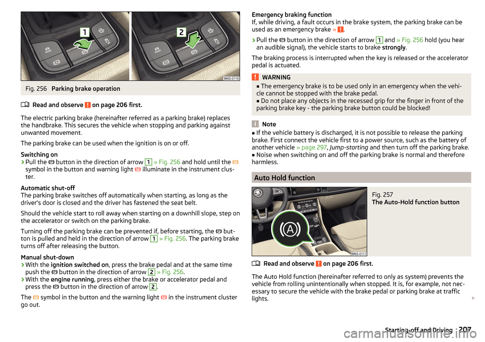
Fig. 256
Parking brake operation
Read and observe
on page 206 first.
The electric parking brake (hereinafter referred as a parking brake) replaces the handbrake. This secures the vehicle when stopping and parking against
unwanted movement.
The parking brake can be used when the ignition is on or off.
Switching on
›
Pull the button in the direction of arrow
1
» Fig. 256 and hold until the
symbol in the button and warning light illuminate in the instrument clus-
ter.
Automatic shut-off
The parking brake switches off automatically when starting, as long as the
driver's door is closed and the driver has fastened the seat belt.
Should the vehicle start to roll away when starting on a downhill slope, step on
the accelerator or switch on the parking brake.
Turning off the parking brake can be prevented if, before starting, the but-
ton is pulled and held in the direction of arrow
1
» Fig. 256 . The parking brake
turns off after releasing the button.
Manual shut-down
›
With the ignition switched on , press the brake pedal and at the same time
push the button in the direction of arrow
2
» Fig. 256 .
›
With the engine running , press either the brake or accelerator pedal and
press the button in the direction of arrow
2
.
The symbol in the button and the warning light
in the instrument cluster
go out.
Emergency braking function
If, while driving, a fault occurs in the brake system, the parking brake can be
used as an emergency brake »
.
›
Pull the
button in the direction of arrow
1
and » Fig. 256 hold (you hear
an audible signal), the vehicle starts to brake strongly.
The braking process is interrupted when the key is released or the accelerator
pedal is actuated.
WARNING■ The emergency brake is to be used only in an emergency when the vehi-
cle cannot be stopped with the brake pedal.■
Do not place any objects in the recessed grip for the finger in front of the
parking brake key - the parking brake button could be blocked!
Note
■ If the vehicle battery is discharged, it is not possible to release the parking
brake. First connect the vehicle first to a power source, such as the battery of
another vehicle » page 297, Jump-starting and then turn off the parking brake.■
Noise when switching on and off the parking brake is normal and therefore
harmless.
Auto Hold function
Fig. 257
The Auto-Hold function button
Read and observe on page 206 first.
The Auto Hold function (hereinafter referred to only as system) prevents the
vehicle from rolling unintentionally when stopped. It is, for example, not nec-
essary to secure the vehicle with the brake pedal or parking brake at traffic
lights.
207Starting-off and Driving
Page 299 of 344
›Firmly screw the inflation hose 3 onto the tyre inflater bottle 10. The film on
the cap is pierced automatically.›
Remove the plug from the inflation hose
3
and plug the open end fully onto
the tyre valve.
›
Hold the bottle
10
with the bottom facing upwards and fill all of the sealing
agent from the tyre inflator bottle into the tyre.
›
Remove the filler plug from the tyre valve.
›
Screw in the valve insert using the valve remover
2
.
Inflating
›
Screw the air compressor tyre inflation hose
7
» Fig. 349 on page 296 firmly
onto the tyre valve.
›
For vehicles with manual transmission , set the lever in the neutral position.
›
On vehicles with automatic transmission , place the selector lever in the P
position.
›
Start the engine.
›
Plug the connector
6
into 12 volt socket » page 97.
›
Switch on the air compressor with the ON and OFF switch
9
.
›
Once a tyre inflation pressure of 2.0-2.5 bar is reached, turn off the air com-
pressor. Maximum run time of 6 minutes » .
›
If you cannot reach an air pressure of 2.0 - 2.5 bar, unscrew the tyre inflation
hose
7
from the tyre valve.
›
Drive the vehicle approx. 10 metres forwards or backwards to allow the seal-
ing agent to “distribute” in the tyre.
›
Firmly screw the tyre inflation hose
7
back onto the tyre valve and repeat
the inflation process.
›
Stick the corresponding sticker
1
on the dashboard in the driver's field of
view.
Once a tyre inflation pressure of 2.0 – 2.5 bar is achieved, continue the journey
at a maximum speed of 80 km/h (50 mph).
WARNING■ If it is not possible to inflate the tyre to at least. 2.0 bar, the damage is
too great. The sealing agent cannot be used to seal the tyre. Stop driv-
ing! Seek help from a specialist garage.■
The tyre inflation hose and air compressor may get hot as the tyre is be-
ing inflated – risk of burning.
CAUTIONSwitch off the air compressor after running 6 minutes at the most – risk of
overheating! Allow the air compressor to cool a few minutes before switching
it on again.
Information for driving with repaired tyres
Read and observe
on page 296 first.
The inflation pressure of the repaired tyre must be checked after driving for 10minutes.
If the tyre inflation pressure is 1.3 bar or less
›
The tyre cannot be properly sealed with the breakdown kit.
Do not drive
the vehicle! Seek help from a specialist garage.
If the tyre inflation pressure is 1.3 bar or more
›
Set the tyre pressure back to the correct value » page 286.
›
Continue driving carefully to the nearest specialist garage at a maximum
speed of 80 km/h (50 mph).
WARNINGA tyre filled with sealant has the same driving characteristics as a standard
tyre. The following guidelines must be observed.■
Do not drive faster than 80 km/h (50 mph).
■
Avoid accelerating at full throttle, sharp braking and fast cornering.
Jump-starting
Introduction
This chapter contains information on the following subjects:
Jump-starting using the battery from another vehicle
298WARNING■ The following instructions must be followed at all times when working on
the engine compartment » page 278.■
When handling the vehicle battery, the following warnings must be ob-
served » page 283 .
297Emergency equipment and self-help
Page 300 of 344
WARNING (Continued)■A discharged vehicle battery may already freeze at temperatures just be-
low 0 °C. If the battery is frozen, do not carry out a jump start with the bat-
tery of another vehicle – risk of explosion!■
Never jump-start vehicle batteries with an acid level that is too low – risk
of explosion and caustic burns!
Jump-starting using the battery from another vehicle
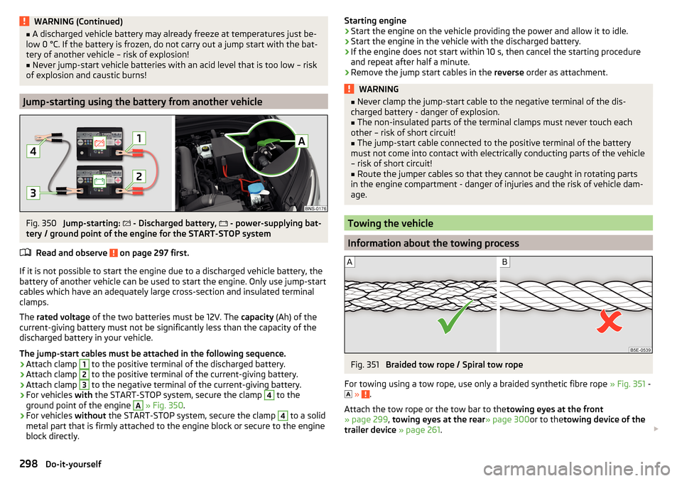
Fig. 350
Jump-starting: - Discharged battery,
- power-supplying bat-
tery / ground point of the engine for the START-STOP system
Read and observe
on page 297 first.
If it is not possible to start the engine due to a discharged vehicle battery, the
battery of another vehicle can be used to start the engine. Only use jump-start
cables which have an adequately large cross-section and insulated terminal
clamps.
The rated voltage of the two batteries must be 12V. The capacity (Ah) of the
current-giving battery must not be significantly less than the capacity of the
discharged battery in your vehicle.
The jump-start cables must be attached in the following sequence.
›
Attach clamp
1
to the positive terminal of the discharged battery.
›
Attach clamp
2
to the positive terminal of the current-giving battery.
›
Attach clamp
3
to the negative terminal of the current-giving battery.
›
For vehicles with the START-STOP system, secure the clamp
4
to the
ground point of the engine
A
» Fig. 350 .
›
For vehicles without the START-STOP system, secure the clamp
4
to a solid
metal part that is firmly attached to the engine block or secure to the engine
block directly.
Starting engine›Start the engine on the vehicle providing the power and allow it to idle.›
Start the engine in the vehicle with the discharged battery.
›
If the engine does not start within 10 s, then cancel the starting procedure
and repeat after half a minute.
›
Remove the jump start cables in the reverse order as attachment.
WARNING■
Never clamp the jump-start cable to the negative terminal of the dis-
charged battery - danger of explosion.■
The non-insulated parts of the terminal clamps must never touch each
other – risk of short circuit!
■
The jump-start cable connected to the positive terminal of the battery
must not come into contact with electrically conducting parts of the vehicle
– risk of short circuit!
■
Route the jumper cables so that they cannot be caught in rotating parts
in the engine compartment - danger of injuries and the risk of vehicle dam-
age.
Towing the vehicle
Information about the towing process
Fig. 351
Braided tow rope / Spiral tow rope
For towing using a tow rope, use only a braided synthetic fibre rope » Fig. 351 -
»
.
Attach the tow rope or the tow bar to the towing eyes at the front
» page 299 , towing eyes at the rear » page 300or to thetowing device of the
trailer device » page 261 .
298Do-it-yourself
Page 301 of 344
Conditions for towing.Cars with automatic gearboxes must not be towed with the rear wheels
raised - there is a risk of gearbox damage!
If the gearbox has no oil, your vehicle must be towed with the front axle
raised clear of the ground or on a breakdown vehicle or trailer.
The maximum towing speed is 50 km/h.
The vehicle must be transported on a special breakdown vehicle or trailer
if it is not possible to tow in the vehicle in the way described or if the tow-
ing distance is greater than 50 km.
Driver of the tow vehicle›
On vehicles with manual transmission , engage gear slowly when starting.
›
On vehicles with automatic transmission , accelerate with particular care.
›
Only then approach correctly when the rope is taut.
Driver of the towed vehicle
›
If possible, the vehicle should be towed with the engine running. Operate the
brake booster and power steering only if the engine is running, otherwise
the brake pedal must be depressed more strongly and more power has to be
directed to the steering.
›
If it is not possible to start the engine, switch on the ignition so that the
steering wheel is not locked and so that the turn signal lights, windscreen
wipers and windscreen washer system can be used.
›
Take the vehicle out of gear or move the selector lever into position N if the
vehicle is fitted with an automatic gearbox.
›
Always keep the tow rope taut during the towing procedure.
WARNING■ Wound tow ropes must not be used for towing » Fig. 351- , the towing
eye may unscrew out of the vehicle - risk of accident.■
Ensure tow rope is not twisted - risk of accident.
CAUTION
■ Do not tow-start the engine – risk of damaging the engine! The battery from
another vehicle can be used as a jump-start aid » page 297, Jump-starting .■
In the case of off-road towing manoeuvres, for both vehicles there is the risk
that the fastening parts could be overloaded and damaged.
Note
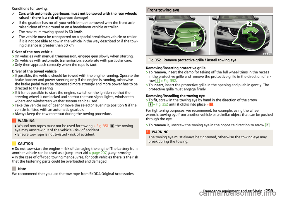
We recommend that you use the tow rope from ŠKODA Original Accessories.Front towing eyeFig. 352
Remove protective grille / install towing eye
Removing/inserting protective grille
›
To remove , insert the clamp for taking off the full wheel trims in the recess
in the protective grille and remove the protective grille in the direction of ar-
row
1
» Fig. 352 .
›
To insert , insert the protective grille in the opening and push in gently. The
protective grille must engage firmly.
Removing/installing the towing eye
›
To fit, screw in the towing eye by hand in the direction of the arrow
2
» Fig. 352 until it clicks into place » .
For tightening purposes, we recommend, for example, using the wheel
wrench, towing eye from another vehicle or a similar object that can be pushed through the eye.
›
To remove it, unscrew the towing eye in the opposite direction to arrow
2
.
WARNINGThe towing eye must always be tightened, otherwise the towing eye may
break during the towing.299Emergency equipment and self-help
Page 326 of 344
Destination managementDestination details192
Favourite192
Storage192
Destination on the map Destinationentered in map
183
Diesel276
Diesel fuel276
Diesel particle filter (DPF)41
Digital Clock44
Digital Service Plan270
Dipped beam66
Dipstick281
Disclaimer applications
120
external devices120
Mobile phones120
Display Coolant temperature
32
Fuel level33
Gear changes44
In the instrument cluster43
MAXI DOT48
Rear centre console33
Display of a low temperature42
Disposal Acceptance and recycling of used vehicles
268
Distance warning249
Diverting calls134
Door Child safety lock
56
Door edge protection55
Emergency locking303
Emergency locking of the driver's door302
Opening/ Closing55
Door alarm43
Door edge protection55
Drive Driving through water
214
DriveGreen213
Driver information system43
Driving Emissions
315
Fuel consumption315
Maximum speed318
through water214
Driving mode251
Adaptive Chassis Control (DCC)251
Comfort252
Eco251
Individual252
Individual mode settings253
Mode selection and Infotainment display252
Normal252
Snow252
Sports252
Driving Mode Selection251
DSR217
DVD147
DVD-Video main menu
153
menu153
Select video source153
DVD video Compatible sources
154
Supported file formats154
Dynamic Road Sign Display Additional display
259
Operation258
Dynamic route200
E
Easy Entry
81
Economical driving212
Economy mode Warning light
42
Edit route194
EDS217
Electrical boot lid set the top position of the lid60
Electrical power windows63
Electric boot lid Force limiter
59
Manual operation59
Open/close60
Electric parking brake206
Electric power windows61
Malfunctions63
Electric tailgate Malfunctions
61
Electric windows Buttons on the driver door
62
Electronic Differential Lock (EDL, XDS)217
Electronic immobiliser202
Elevation178
emergency Jump-starting
298
Starting the engine / stopping at the push of a button
204
Emergency Changing a wheel
291
Hazard warning light system70
Jump-starting297
selector lever release303
Starting the engine / stopping the push of a button
203
Towing the using the tow hitch300
Towing the vehicle298
Tyre repair295
Unlocking/locking the door302
Unlocking / locking the door303
emergency call14, 118
see emergency14
see emergency call14
Emergency call164
Emergency equipment Fire extinguisher
290
First aid kit290
324Index
Page 328 of 344
Genuine parts267
Glasses compartment92
Google Earth ™180, 189
Google Street View ™180
GPS178
Graphical driving recommendations193
H
Hazard warning light system
70
HBA217
Headrests83
Heating109, 110
Air distribution control113
Mirrors76
Seats85
Steering wheel86
Windscreen and rear window72
HHC217
High-beam assistant41
High beam Light Assist
68
Hill Descent Assistant219
Hill Start Assist (HHC)217
hitch263
Hitch261
home address137
Home address185
Hook102
Horn31
I
I-PAD holder
99
I-Size28
Ignition lock203
Images Display
134
main menu151
Operation152
safe removal of the data source132
Select Image Source151
Set to134
Image viewer151
Immobiliser202
import Destinations (online)
188
Objectives (vCard)187
POI categories187
POI categories (online)179, 188
Routes (online)196
Import contacts134
In-car communication126
Inertia reels18
Information about the towing process298
information call118
Information call164
Information system43
Gear recommendation44
MAXI DOT display48
Multifunction display46
Service interval display49
infotainment Description Amundsen
121
bolero122
Columbus121
swing122
Infotainment language131, 139
Infotainment menus126
infotainment online118
Infotainment operation124
Infotainment screen124
Infotainment operation using an application in the external device
127
Infotainment Overview121
Infotainment Restart125
Infotainment screen131, 138
Areas124
Important information123
keyboard125
Maintenance123
Operation124
Input screen Language characters
139
Input screen with keyboard125
Instrument cluster32
Vehicle condition45
Warning lights33
interior light71
Interior lighting71
Ambient lighting72
Interior monitor58
Intermediate target192
Internet171
ISOFIX27
J
Jack
291
- fit295
Journey47
Jukebox149
Jump-starting297, 298
K
KESSY Ignition on / off
203
Starting engine / Stopping203
Unlocking / locking53
key Ignition on / off
203
Starting engine / Stopping203
Key Changing battery
300, 301
Take out emergency key53
keyboard125
key CAR201
326Index
Page 335 of 344
SmartLink172
Android Auto173
Apple CarPlay174
Application ŠKODA One App176
Introduction to the subject172
Main menu173
MirrorLink®175
Set to136, 141
SMS168
Snow chains289
Sockets 12-volt socket in the interior
97
12 volt socket in luggage compartment97
230 V97
Software Update129, 133
Software updates139
SOS button see emergency call
14
sound130
Sound138
sound system130
Spare wheel287
Removing / stowing292
Removing / stowing (sound system)293
speech enhancement126
Speed limitations193
Speed limiter38 , 241
Speed regulating system Warning light
38
Speed symbol288
Spoiler267
Spurhalteassistent254
SSID132
Stabilisation system215
Stability Control (ESC)36, 216
standby125
START-STOP204
Jump-starting298
manually activate/ deactivate system205
operation204
Warning light41
START-STOP system204
Start engine203
Immobiliser202
Jump-starting298
starter button Ignition on / off
203
Starting engine / Stopping203
Starter button Lock / unlock the steering lock
202
Problems with the engine start204
Starting the engine Jump-starting
297
Start the route guidance192
status line Navigation
138
Status line124, 180
Telephone158, 159
Steering lock (KESSY system)35
Steering wheel Buttons
45
Heating86
Proper posture13
Setting13
Stop engine203
Stopping see Parking
208
Storage compartment Glasses compartment
92
In the front centre console89
in the rear centre console95
on the driver's side88
on the front passenger side93
under the front arm rest92
under the passenger seat93
Storage compartments87
Storage net92
Stored destinations Final destinations184
target memory185
Store destination192
Storing seats
79
Stowage compartments in the doors
89
Sunblind for the tilt / slide sunroof65
Sun visor73
Supported sources media
150
surround130
swing infotainment Description
122
Switch Car battery
285
Switching the lights on and off66
Switch off Alarm
57
Switch off the ignition203
switch on / offTraffic dynamic route
200
Switch on ignition203
system information129
System information133, 139
T
Tablet holder
99
Tailgate58
target memory185
Technical data313
Telefon Bluetooth-Profile
160
telephone conditions for pairing
160
Telephone Additional telephone
157
Breakdown call164
333Index