technical data SKODA OCTAVIA 2007 1.G / (1U) Owner's Manual
[x] Cancel search | Manufacturer: SKODA, Model Year: 2007, Model line: OCTAVIA, Model: SKODA OCTAVIA 2007 1.G / (1U)Pages: 288, PDF Size: 15.19 MB
Page 244 of 288
Fuses and light bulbs243
Using the systemSafetyDriving TipsGeneral MaintenanceBreakdown assistanceTechnical Data
Fuses and light bulbs
Electric fuses
Replacing fuses
Defect fuses must be replaced.
Individual electrical circuits are protected by fuses. The fuses are located
on the left side of the dash panel behind the safety cover and under the
cover in the engine compartment on the left.
– Switch the ignition off and also the electrical component affected.
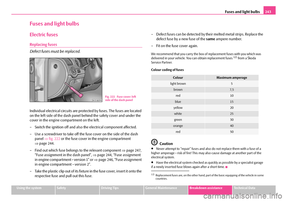
– Use a screwdriver to take off the fuse cover on the side of the dash panel ⇒fig. 222 or the fuse cover in the engine compartment
⇒ page 244.
– Find out which fuse belongs to the relevant component ⇒page 247,
“Fuse assignment in the dash panel”, ⇒page 244, “Fuse assignment
in engine compartment - version 1” or ⇒page 246, “Fuse assignment
in engine compartment - version 2”.
– Take the plastic clip out of its fixture in the fuse cover, insert it onto the respective fuse and pull out this fuse. – Defect fuses can be detected by their melted metal strips. Replace the
defect fuse by a new fuse of the same ampere number.
– Fit on the fuse cover again.
We recommend that you carry the box of replacement fuses with you which was
delivered in your vehicle. You can obtain replacement fuses 12) from a Škoda
Service Partner.
Colour coding of fuses
Caution
•Never attempt to “repair” fuses and also do not replace them with a fuse of a
higher amperage - risk of fire! This may also cause damage at another part of the
electrical system.
•Have the electrical system checked as quickly as possible by a specialist garage
if a newly inserted fuse blows again after a short time.
Fig. 222 Fuse cover: left
side of the dash panel
12)Replacement fuses are, on the other hand, part of the basic equipping of the vehicle in some
countries.
ColourMaximum amperage
light brown5
brown7,5
red10
blue15
yellow20
white25
green30
orange40
red50
NKO A5 20 MR08.book Page 243 Wednesday, April 11, 2007 2:54 PM
Page 246 of 288
Fuses and light bulbs245
Using the systemSafetyDriving TipsGeneral MaintenanceBreakdown assistanceTechnical Data
F11Lambda probe upstream of catalytic converter,
engine control unit10
F12Lambda probe downstream of catalytic converter10
F13Control unit for automatic gearbox15
F14Not assigned
F15Coolant pump10
F16Windshield wiper lever and turn signal light lever5
F17Instrument cluster5
F18Audio amplifier (sound system)30
F19Radio15
F20Phone5
F21Not assigned
F22Not assigned
F23Engine control unit10
F24Control unit for CAN databus5
F25Not assigned
F26Not assigned
F27Not assigned
F28Engine control unit25
F29Actuation for coolant pump after-running5
F30Control unit for auxiliary heating20
F31Front window wiper30
F32Not assigned
F33Not assigned
F34Not assigned
No.Power consumerAmperes
F35Not assigned
F36Not assigned
F37Not assigned
F38Radiator fan, valves10
F39Clutch pedal switch, brake pedal switch5
F40Ignition coils20
F41Not assigned
F42Actuation of fuel pump5
F43Not assigned
F44Not assigned
F45Not assigned
F46Not assigned
F47Central control unit, Left main headlights30
F48Central control unit, Right main headlights30
F49Power supply for terminal 15 (ignition on)40
F50Not assigned
F51Not assigned
F52Power supply relay - terminal X a)40
F53Accessory equipment50
F54Not assigned
a)In order not to drain the battery unnecessarily when starting the engine, the electrical
components of this terminal are automatically switched off.
No.Power consumerAmperes
NKO A5 20 MR08.book Page 245 Wednesday, April 11, 2007 2:54 PM
Page 248 of 288
Fuses and light bulbs247
Using the systemSafetyDriving TipsGeneral MaintenanceBreakdown assistanceTechnical Data
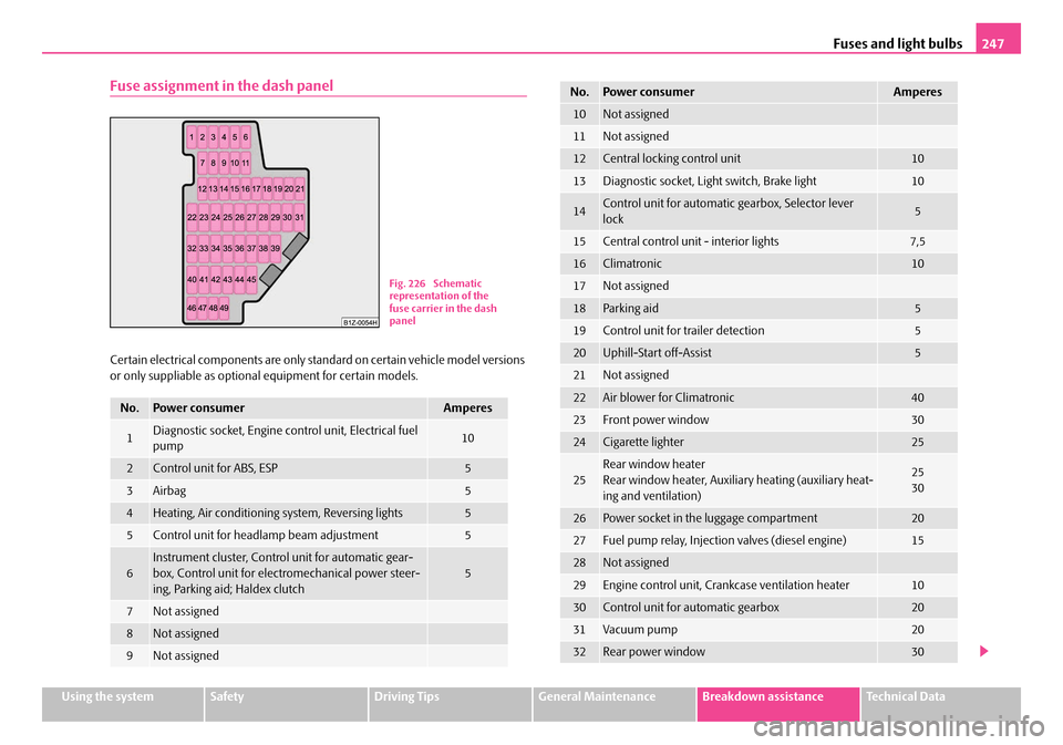
Fuse assignment in the dash panel
Certain electrical components are only standard on certain vehicle model versions
or only suppliable as optional equipment for certain models.
No.Power consumerAmperes
1Diagnostic socket, Engine co ntrol unit, Electrical fuel
pump10
2Control unit for ABS, ESP5
3Airbag5
4Heating, Air conditioning system, Reversing lights5
5Control unit for headla mp beam adjustment5
6Instrument cluster, Contro l unit for automatic gear-
box, Control unit for elec tromechanical power steer-
ing, Parking aid; Haldex clutch5
7Not assigned
8Not assigned
9Not assigned
Fig. 226 Schematic
representation of the
fuse carrier in the dash
panel
10Not assigned
11Not assigned
12Central locking control unit10
13Diagnostic socket, Light switch, Brake light10
14Control unit for automatic gearbox, Selector lever
lock5
15Central control unit - interior lights7,5
16Climatronic10
17Not assigned
18Parking aid5
19Control unit for trailer detection5
20Uphill-Start off-Assist5
21Not assigned
22Air blower for Climatronic40
23Front power window30
24Cigarette lighter25
25Rear window heater
Rear window heater, Auxiliar y heating (auxiliary heat-
ing and ventilation)25
30
26Power socket in the luggage compartment20
27Fuel pump relay, Injection valves (diesel engine)15
28Not assigned
29Engine control unit, Crankcase ventilation heater10
30Control unit for automatic gearbox20
31Vacuum pump20
32Rear power window30
No.Power consumerAmperes
NKO A5 20 MR08.book Page 247 Wednesday, April 11, 2007 2:54 PM
Page 250 of 288
Fuses and light bulbs249
Using the systemSafetyDriving TipsGeneral MaintenanceBreakdown assistanceTechnical Data
WARNING
•Bulbs H7 and H1 are pressurised and may burst when changing the bulb
- risk of injury!
•It is recommended to wear gloves and eye protection when changing a
light bulb.
•Gas discharge bulbs* (xenon bulbs) op erate with a high voltage, profes-
sional knowledge is required - danger to life!
Caution
Do not take hold of the glass bulb with naked fingers (even the smallest amount of
dirt reduces the working life of the light bu lb). Use a clean cloth, serviette or some-
thing similar.
Note
This Owner's Manual only describes the replacement of bulbs where it is assumed
that no major complications wi ll arise. Other light bulbs should be changed by your
specialist garage.
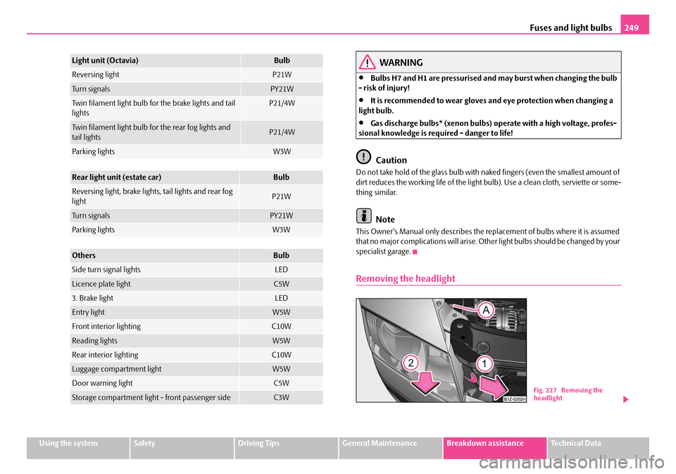
Removing the headlight
Light unit (Octavia)Bulb
Reversing lightP21W
Tu r n s i g n a l sPY21W
Twin filament light bulb for the brake lights and tail
lightsP21/4W
Twin filament light bulb for the rear fog lights and
tail lightsP21/4W
Parking lightsW3W
Rear light unit (estate car)Bulb
Reversing light, brake lights, tail lights and rear fog
lightP21W
Tu r n s i g n a l sPY21W
Parking lightsW3W
OthersBulb
Side turn signal lightsLED
Licence plate lightC5W
3. Brake lightLED
Entry lightW5W
Front interior lightingC10W
Reading lightsW5W
Rear interior lightingC10W
Luggage compartment lightW5W
Door warning lightC5W
Storage compartment light - front passenger sideC3WFig. 227 Removing the
headlight
NKO A5 20 MR08.book Page 249 Wednesday, April 11, 2007 2:54 PM
Page 252 of 288
Fuses and light bulbs251
Using the systemSafetyDriving TipsGeneral MaintenanceBreakdown assistanceTechnical Data
Low beam
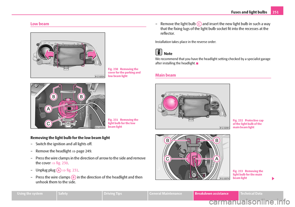
Removing the light bulb for the low beam light
– Switch the ignition and all lights off.
– Remove the headlight ⇒page 249.
– Press the wire clamps in the direction of arrow to the side and remove the cover ⇒fig. 230 .
– Unplug plug ⇒fig. 231 .
– Press the wire clamps in the direction of the headlight and then unhook them to the side. – Remove the light bulb and insert the new light bulb in such a way
that the fixing lugs of the light bulb socket fit into the recesses at the
reflector.
Installation takes place in the reverse order.
Note
We recommend that you have the headlight setting checked by a specialist garage
after installing the headlight.
Main beam
Fig. 230 Removing the
cover for the parking and
low beam light
Fig. 231 Removing the
light bulb for the low
beam light
AA
AB
AC
Fig. 232 Protective cap
of the light bulb of the
main beam light
Fig. 233 Removing the
light bulb for the main
beam light
NKO A5 20 MR08.book Page 251 Wednesday, April 11, 2007 2:54 PM
Page 254 of 288
Fuses and light bulbs253
Using the systemSafetyDriving TipsGeneral MaintenanceBreakdown assistanceTechnical Data
Light unit (Octavia)
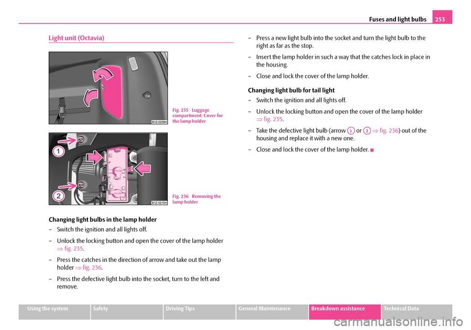
Changing light bulbs in the lamp holder
– Switch the ignition and all lights off.
– Unlock the locking button and open the cover of the lamp holder
⇒ fig. 235 .
– Press the catches in the directio n of arrow and take out the lamp
holder ⇒fig. 236 .
– Press the defective light bulb into the socket, turn to the left and
remove. – Press a new light bulb into the socket and turn the light bulb to the
right as far as the stop.
– Insert the lamp holder in such a wa y that the catches lock in place in
the housing.
– Close and lock the cover of the lamp holder.
Changing light bulb for tail light
– Switch the ignition and all lights off.
– Unlock the locking button and open the cover of the lamp holder ⇒fig. 235 .
– Take the defective light bulb (arrow or ⇒fig. 236 ) out of the
housing and replace it with a new one.
– Close and lock the cover of the lamp holder.
Fig. 235 Luggage
compartment: Cover for
the lamp holder
Fig. 236 Removing the
lamp holder
A1A2
NKO A5 20 MR08.book Page 253 Wednesday, April 11, 2007 2:54 PM
Page 256 of 288
Technical Data255
Using the systemSafetyDriving TipsGeneral MaintenanceBreakdown assistanceTechnical Data
Technical Data
Technical Data
General comments
The details given in the official vehicle registration documents always take prece-
dence over the details in th e Owner's Manual. Please refer to the official vehicle
registration documents or consult your Škoda Service Partner concerning the
engine with which your vehicle is equipped.
Used abbreviations
Performances
The listed performance values were de termined without performance-reducing
equipment, e.g. air conditioning system.
Weight
The loading capacity is reduced in line with the range of the special equipment. The
unloaden weight contains a fuel tank topped up to 90%. A driver with a weight of
75 kg is also included in the value.
Identification details
AbbreviationImportance
kWKilowatt, measuring unit for the engine output
rpmEngine revolutions per minute
NmNewton meter, measuring unit for the engine torque
g/kmdischarged quantity of carbon dioxide in grams per
driven kilometer
RONResearch octane number, measuring unit for the
knocking resistance of petrol
FSIFuel Stratified Injection
M5 / M65-speed/6-speed manual gearbox
AG66-speed automatic gearbox
DQ66-speed automatic gearbox Tiptronic
DPFDiesel particle filterFig. 239 Vehicle data
sticker
NKO A5 20 MR08.book Page 255 Wednesday, April 11, 2007 2:54 PM
Page 257 of 288

Technical Data
256
Vehicle data sticker
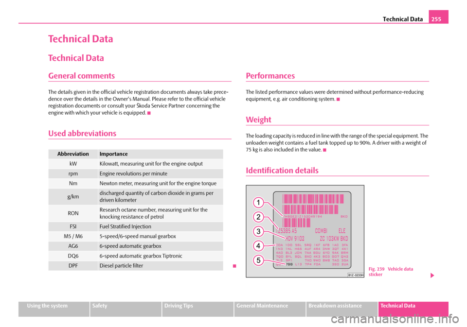
The vehicle data sticker ⇒page 255, fig. 239 is located on the floor of the luggage
compartment and is also stated in the Service schedule.
The vehicle data sticker co ntains the following data:
Vehicle identification number (VIN)
Vehicle type
Gearbox code, paint number, interior equipment number, engine output,
engine code
Partial description of the vehicle
7GG - vehicles with DPF
Vehicle identification number (VIN)
The vehicle identification num ber - VIN (vehicle body number) is stamped into the
engine compartment on the right hand shoc k absorber dome. This number is also
located on a sign on the lower left hand edge below the windscreen.
Engine number
The engine number is stamped into the engine block.
Type plate (production plate)
The type plate is located in the lower area of the left centre column.
Homologation sign
The homologation sign is located on the in side of the bonnet next to the lock. Vehi-
cles for certain countries do not have an homologation sign.
Sticker on inside of fuel filler flap
The stickers are affixed to the inside of th e fuel filler flap and contain the following
information:
•The prescribed types of fuel,
•Tyre si z e,
•Tyre pressure.
Fuel consumption according to the regulations
(99/100/EU)
Depending on the range of the special equipment, style of driving, traffic situation,
weather influences and vehi cle condition, the consumption values which in prac-
tice result when using the vehicle ca n deviate from the indicated values.
Urban traffic
The consumption measurement in urban traf fic begins with starting of the cold
engine. Afterwards the normal urban traffic is simulated.
Non-urban traffic
For the consumption measurement in non-ur ban traffic the vehicle, as in daily
motoring, is accelerated and braked several times in all gears. The vehicle speed
changes within the range from 0 to 120 km/h.
Combined traffic
The consumption value in the combined traf fic consists of 37% from the value for
the urban traffic and of 63% from the value for the non-urban traffic.
A1
A2
A3
A4
A5
NKO A5 20 MR08.book Page 256 Wednesday, April 11, 2007 2:54 PM
Page 258 of 288

Technical Data257
Using the systemSafetyDriving TipsGeneral MaintenanceBreakdown assistanceTechnical Data
Dimensions
Dimensions (mm)
OCTAVIAOCTAVIA RSESTATE CARCOMBI 4x4COM B I R SSCOUT
Length457245784572457245794581
Width176917691769176917691784
Width including exterior mirror197319731973197319731973
Height1462/1485a)/
1449b)
a)The value is valid for vehicles with rough road package.b)The value corresponds to the status with SPORT package.
14471468/1490a)/
1455b)1495/1520a)14511533
Wheel base257825772578257825772578
Tr a c k g a u g e f r o n t / r e a r1539/15281526/15141539/15281533/15221526/15141534/1515
NKO A5 20 MR08.book Page 257 Wednesday, April 11, 2007 2:54 PM
Page 259 of 288

Technical Data
258
1.4 ltr./59 kW - EU4
Engine
Performances
Fuel consumption (in ltr./100 km) and CO
2 emission (in g/km)
Power outputkW per rpm59/5000
Maximum torqueNm per rpm132/3800
Number of cylinders/Displacement (cm3)4/1390
Fuel - unleaded petrol min. RON95
OCTAVIA
M5COMBIM5
Maximum speedkm/h173172
Acceleration 0 - 100 km/hs14,214,3
OCTAVIA M5COMBIM5
Urban9,69,6
Non-urban5,65,6
Combination7,07,0
CO2 emission - combination167167
NKO A5 20 MR08.book Page 258 Wednesday, April 11, 2007 2:54 PM