instrument cluster SKODA OCTAVIA 2009 2.G / (1Z) Owner's Guide
[x] Cancel search | Manufacturer: SKODA, Model Year: 2009, Model line: OCTAVIA, Model: SKODA OCTAVIA 2009 2.G / (1Z)Pages: 304, PDF Size: 19.56 MB
Page 199 of 304
Intelligent Technology
198
Brake Assist*During a severe brake application (e.g. if a hazard exists), the Brake Assist increases the braking force and thus makes it possible to rapidly produce the pressure required in the brake system. The majority of drivers do
apply the brakes in good time in dangerous situations,
but do not depress the brake pedal with su
fficient pressure. Consequently, it is not
possible for the vehicle to achieve its maximum deceleration and the vehicle covers a greater distance than necessary. The Brake Assist is activated by the very quick operation of the brake pedal. In such cases, a much greater braking pressure ex
ists than during a normal brake applica-
tion. This makes it possible, even with a relatively low resistance of the brake pedal, to produce an adequate pressure in the brake system in the shortest possible time, which is required for maximum deceleration of the vehicle. You must apply the brake pedal firmly and hold it in this po
sition in order to achieve the shortest
possible braking distance. The Brake Assist is able to help you achieve a shorter braking distance in emergency situations by rapidly producing the pressure
required in the brake system. It fully
exploits the attributes of the ABS. After you release the brake pedal, the function of the Brake Assist is automatically switched off and the brakes operate in the normal way. The Brake Assist is part of the ESP system. If a fault occurs in the ESP, the Brake Assist function is also not available.
Further information on the ESP
⇒page 193.
WARNING
•
The Brake Assist is also not able to overcome the physical limits of your
vehicle in terms of the braking distance required.•
Adapt your speed to the conditions of the road surface and to the traffic
situation.•
The increased safety offered by the Brake Assist must not tempt you to
take a greater safety risk than otherwise.
Uphill-Start
off-Assist*
The uphill-start off-assist makes it much easier to start off on steep hills. The system assists a start off by holding the brake pr
essure produced by the brake pedal actu-
ation for approx. 2 seconds after releasing the brake pedal. The driver can therefore move his foot from the brake pedal to th
e accelerator pedal and start off on the
slope, without having to actuate the hand
brake. The brake pressure drops gradually
the more you operate the accelerator pedal. If the vehicle does not start off within 2 seconds, it starts to roll back. The uphill-start off-assist is active in the ev
ent of a 5% slope, if the vehicle door is
closed. It is alwa
ys active on slopes when in forward or reverse start off. When
driving downhill, it is inactive.Electromechanical power steeringThe power steering enables you to steer
the vehicle with le
ss physical force.
With the electromechanical power steering, the steering assist is automatically adapted to the speed and to the steering angle. It is still possible to fully steer the vehicle if the power steering fails or if the engine is not running (vehicle being towed in). The
only difference is that greater physical
effort is required. If there is a fault in the power steering, the warning light
or lights up in the
instrument cluster
⇒page 35.
WARNING
Contact your specialist
garage if the power steering is defective.
se0.1.book Page 198 Frida
y, April 10, 2009 3:19 PM
Page 228 of 304

Inspecting and replenishing
227
Using the system
Safety
Driving Tips
General Maintenance
Breakdown assistance
Technical Data
Engine oilCheck engine oil level The dipstick indicates the level of oil in the engine.Checking the oil level – Ensure that the vehicle is positioned on a level surface. – Switch the engine off. – Open the bonnet
⇒
in “Working in the engine compartment” on
page 225.
– Wait a few minutes and pull out the oil dipstick.– Wipe off the dipstick with a clea
n cloth and insert it again fully.
– Then withdraw the dipstick ag
ain and read off the oil level.
Oil level within range – You must
not
top up the oil.
Oil level within range –You
may
top up the oil. It is possible that the oil level may then be
within range after doing this.
Oil level within range –You
must
top up the oil
⇒
page 228. It is sufficient, once this is done,
to keep the oil level within range .
It is normal for the engine to consume oi
l. The oil consumption may be as much as
0.5 l/1 000 km depending on your style of driving and the conditions under which you operate your vehicle. The oil consumpt
ion may be slightly higher than this
during the first 5 000 kilometres. One should therefore check the oil level at regular intervals, preferably every time after the fuel tank is filled or after driving for long stretches. We recommend maintaining the oil level within the range -
but not above this
,
if the engine has been operating at hi
gh loads, for example during a lengthy
motorway trip during the summer months,
towing a trailer or negotiating a high
mountain pass. The warning light in the instrument cluster* will indicate
⇒page 35, “Engine oil
pressure
” whether the oil level is too low. In this case, check the oil level as soon
as possible. Top up with an appropriate quantity of oil.
Caution
•
The oil level must on no account ex
tend beyond the range . Danger of
damaging the cata
lytic converter.
•
Do not continue your journey
if for some reason it is not possible under the
conditions prev
ailing to top up with oil.
Switch of the engine and contact
and
obtain professional assistance from a specialist garage.
Note
Engine oil specifications
⇒page 271, “Technical Data”.
Fig. 211 Dipstick
AA
AB
AA
AC
AB
AA
AA
se0.1.book Page 227 Frida
y, April 10, 2009 3:19 PM
Page 230 of 304
Inspecting and replenishing
229
Using the system
Safety
Driving Tips
General Maintenance
Breakdown assistance
Technical Data
also protects the cooling and heating system from corrosion. It also prevents the formation of scale and significantly increases the boiling point of the coolant. You must therefore not reduce the concentr
ation of antifreeze agent in the coolant
by adding water, also not during the summ
er months or in countries with a warm
climate.
The concentration of coolant additive in the coolant must be at least
40%. You can increase the amount of antifreeze
in the coolant if a higher concentration
of antifreeze is necessary for climatic
reasons but only up to 60% (antifreeze
protection down to approx. -40°C). The an
tifreeze protection tails off above that
concentration. Vehicles exported to countries with a co
ld climate (e.g. Sweden, Norway, Finland)
are already factory-filled with a coolant wh
ich offers antifreeze protection down to
about -35°C. In these countries the concentr
ation of coolant additive should be at
least 50 %. Coolant The cooling system is factory-filled with co
olant (purple in colour), which complies
with the specification TL-VW 774 G. We recommend that you use the same c
oolant additive - G12 PLUS-PLUS (purple
in colour) for toppi
ng up the system.
Please contact an authorised Škoda Service Partner if you have any questions regarding the coolant or if you wish to fill up with a different coolant. An authorised Škoda Service Partner can al
so supply you with the correct coolant
additives.
Caution
•
Other coolant additives may cause operational problems which, in partic-
ular, involves significantly redu
cing the anticorrosion effect.
•
Any faults or problems resulting from corrosion may cause a loss of
coolant and, as a consequence of th
is, result in major engine damage.
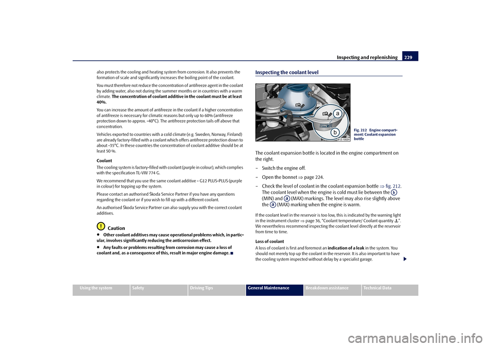
Inspecting the coolant levelThe coolant expansion bottle is loca
ted in the engine compartment on
the right. – Switch the engine off. – Open the bonnet
⇒
page 224.
– Check the level of coolant in the coolant expansion bottle
⇒
fig. 212
.
The coolant level when the engine is cold must lie between the (MIN) and (MAX) markings. The level may also rise slightly above the (MAX) marking when the engine is warm.
If the coolant level in the reservoir is too low, this is indicated by the warning light in the instrument cluster
⇒page 36, “Coolant temperat
ure/ Coolant quantity
”.
We nevertheless recommend in
specting the coolant level directly at the reservoir
from time to time. Loss of coolant A loss of coolant is first and foremost an
indication of a leak
in the system. You
should not merely top up the coolant in the
reservoir. It is also important to have
the cooling system inspected without delay by a specialist garage.
Fig. 212 Engine compart- ment: Coolant expansion bottle
Ab
Aa
Aa
se0.1.book Page 229 Frida
y, April 10, 2009 3:19 PM
Page 260 of 304

Fuses and light bulbs
259
Using the system
Safety
Driving Tips
General Maintenance
Breakdown assistance
Technical Data
Fuse cover in engine compartment The fuse box in the engine comp
artment exists in two different
versions. You can determine which version your vehicle is fitted with after removing the fuse cover at the location of the fuses.On some vehicles, the battery cover
must be removed before removing
the fuse cover
⇒
page 232.
Removing fuse cover – Move the circlips
⇒
fig. 238
as far as the stop, the symbol
appears behind the circlip and remove the cover.
Installing fuse cover – Position the fuse cover on the fuse box and push the circlips as far
as the stop - the symbol
is visible behind the circlip.
Caution
•
When unlocking and locking the fuse cover,
it must be pressed on the sides to
the box, otherwise damage can
occur to the locking mechanism.
•
Carefully position the fuse cover in th
e engine compartment. If the cover was
not correctly positioned, water can get into
the fuses and this results in a damage
to the vehicle!
Fuse assignment in engine compartmentCertain electrical components are only standard on certain vehicle model versions or only suppliable as optional
equipment for certain models.
Fig. 238 Fuse cover in engine compartment
AA
AA
No.
Power consumer
Amperes
F1
Not assigned
F2
Control unit for automatic gearbox DQ 200
30
F3
Measuring circuit
5
F4
Valves for ABS
30/20
F5
Control unit for automatic gearbox
15
F6
Instrument cluster, windshield
wiper lever and turn sig-
nal light lever
5
F7
Power suppy terminal 15, Starter
40
F8
Radio
15
F9
Phone
5
F10
Engine control unit, Main relay
5/10
F11
Control unit for auxiliary heating
20
F12
Control unit for CAN databus
5
Fig. 239 Schematic repre- sentation of fuse carrier in engine compartment
se0.1.book Page 259 Frida
y, April 10, 2009 3:19 PM
Page 261 of 304
Fuses and light bulbs
260
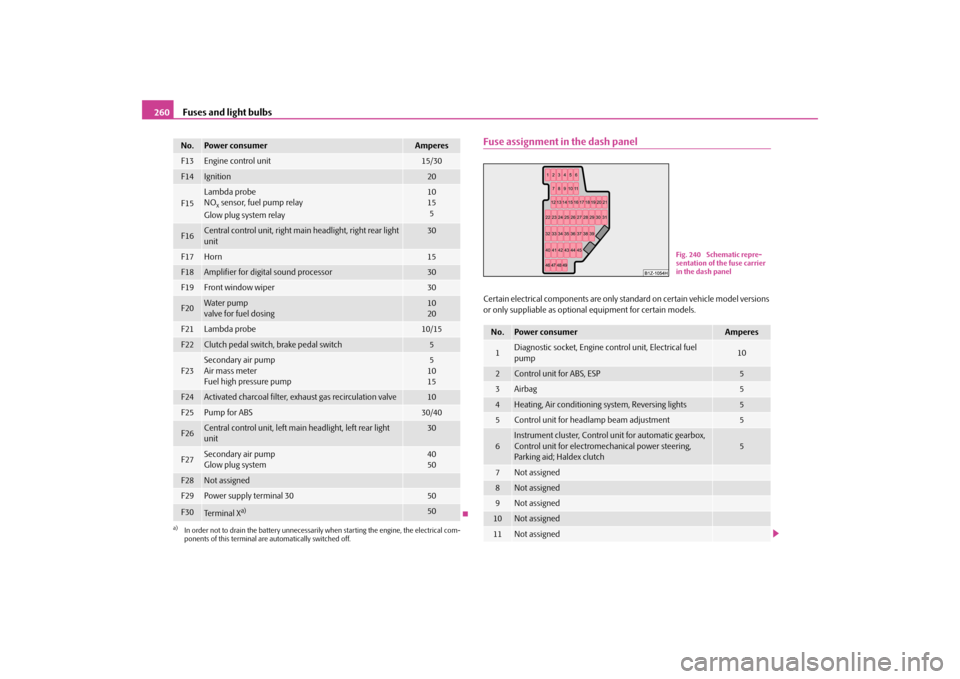
Fuse assignment in the dash panelCertain electrical components are only standard on certain vehicle model versions or only suppliable as optional
equipment for certain models.
F13
Engine control unit
15/30
F14
Ignition
20
F15
Lambda probe NO
x sensor, fuel pump relay
Glow plug system relay
10 15 5
F16
Central control unit, right main headlight, right rear light unit
30
F17
Horn
15
F18
Amplifier for digital sound processor
30
F19
Front window wiper
30
F20
Water pumpvalve for fuel dosing
1020
F21
Lambda probe
10/15
F22
Clutch pedal switch, brake pedal switch
5
F23
Secondary air pump Air mass meter Fuel high pressure pump
5 10 15
F24
Activated charcoal filter, ex
haust gas recirculation valve
10
F25
Pump for ABS
30/40
F26
Central control unit, left main headlight, left rear light unit
30
F27
Secondary air pump Glow plug system
4050
F28
Not assigned
F29
Power supply terminal 30
50
F30
Te r m i n a l X
a)
50
a)In order not to drain the battery unnecessarily
when starting the engine, the electrical com-
ponents of this terminal are automatically switched off.No.
Power consumer
Amperes
No.
Power consumer
Amperes
1
Diagnostic socket, Engine co
ntrol unit, Electrical fuel
pump
10
2
Control unit for ABS, ESP
5
3
Airbag
5
4
Heating, Air conditioning system, Reversing lights
5
5
Control unit for headla
mp beam adjustment
5
6
Instrument cluster, Control unit for automatic gearbox, Control unit for electromec
hanical power steering,
Parking aid; Haldex clutch
5
7
Not assigned
8
Not assigned
9
Not assigned
10
Not assigned
11
Not assigned
Fig. 240 Schematic repre- sentation of the fuse carrier in the dash panel
se0.1.book Page 260 Frida
y, April 10, 2009 3:19 PM
Page 298 of 304

Index297
Using the system
Safety
Driving Tips
General Maintenance
Breakdown assistance
Technical Data Engine oil . . . . . . . . . . . . . . . . . . . . . . . . . . . . . . . . . . . 227
Changing . . . . . . . . . . . . . . . . . . . . . . . . . . . . . . . . 228
changing . . . . . . . . . . . . . . . . . . . . . . . . . . . . . . . . 228
check . . . . . . . . . . . . . . . . . . . . . . . . . . . . . . . . . . . 227
replenishing . . . . . . . . . . . . . . . . . . . . . . . . . . . . . 228
Warning light . . . . . . . . . . . . . . . . . . . . . . . . . . . . . . 35
Engine oil level
Warning light . . . . . . . . . . . . . . . . . . . . . . . . . . . . . . 40
Engine revolutions counter . . . . . . . . . . . . . . . . . . . . 18
Environment . . . . . . . . . . . . . . . . . . . . . . . . . . . . . . . . 202
Environmental compatibility . . . . . . . . . . . . . 202, 206
ESP . . . . . . . . . . . . . . . . . . . . . . . . . . . . . . . . . . . . . . . . 193
Warning light . . . . . . . . . . . . . . . . . . . . . . . . . . . . . . 37
Exhaust gas
Warning light . . . . . . . . . . . . . . . . . . . . . . . . . . . . . . 35
Exhaust gas inspection
Warning light . . . . . . . . . . . . . . . . . . . . . . . . . . . . . . 35
Explanations . . . . . . . . . . . . . . . . . . . . . . . . . . . . . . . . . . . 6
Exterior mirror . . . . . . . . . . . . . . . . . . . . . . . . . . . . . . . . 73
Exterior mirror heater . . . . . . . . . . . . . . . . . . . . . . . . . . 73
FFirst-aid box . . . . . . . . . . . . . . . . . . . . . . . . . . . . . . . . 245
Fixing net
Combi . . . . . . . . . . . . . . . . . . . . . . . . . . . . . . . . . . . . 87
Octavia . . . . . . . . . . . . . . . . . . . . . . . . . . . . . . . . . . . 86
Fog lights . . . . . . . . . . . . . . . . . . . . . . . . . . . . . . . . . . . . . 62
Indicator light . . . . . . . . . . . . . . . . . . . . . . . . . . . . . 33
Warning light . . . . . . . . . . . . . . . . . . . . . . . . . . . . . . 33
Fog lights with the function Corner . . . . . . . . . . . . . 62
Front airbag . . . . . . . . . . . . . . . . . . . . . . . . . . . . . . . . . 175
Front armrest . . . . . . . . . . . . . . . . . . . . . . . . . . . . . . . 103Fuel . . . . . . . . . . . . . . . . . . . . . . . . . . . . . . . . . . . . . . . . . 219
Diesel fuel . . . . . . . . . . . . . . . . . . . . . . . . . . . . . . . 221
Fuel gauge . . . . . . . . . . . . . . . . . . . . . . . . . . . . . . . . 18
Petrol . . . . . . . . . . . . . . . . . . . . . . . . . . . . . . . . . . . 219
Fuel consumption . . . . . . . . . . . . . . . . . . . . . . . . . . . 202
Saving energy . . . . . . . . . . . . . . . . . . . . . . . . . . . . 202
Fuel gauge . . . . . . . . . . . . . . . . . . . . . . . . . . . . . . . . . . . 18
Fuel reserve
Warning light . . . . . . . . . . . . . . . . . . . . . . . . . . . . . . 41
Full wheel trim . . . . . . . . . . . . . . . . . . . . . . . . . . . . . . . 249
Fuses . . . . . . . . . . . . . . . . . . . . . . . . . . . . . . . . . . . . . . . 258
GGauges . . . . . . . . . . . . . . . . . . . . . . . . . . . . . . . . . . . . . . . 17
Gearbox
mechanical . . . . . . . . . . . . . . . . . . . . . . . . . . . . . . 125
General view
Cockpit . . . . . . . . . . . . . . . . . . . . . . . . . . . . . . . . . . . . 9
Glass roof . . . . . . . . . . . . . . . . . . . . . . . . . . . . . . . . . . . . 55
Glow plug system . . . . . . . . . . . . . . . . . . . . . . . . . . . . 124
Warning light . . . . . . . . . . . . . . . . . . . . . . . . . . . . . . 36
GSM . . . . . . . . . . . . . . . . . . . . . . . . . . . . . . . . . . . 142, 152HHandbrake . . . . . . . . . . . . . . . . . . . . . . . . . . . . . . . . . . 126
Hazard warning light system . . . . . . . . . . . . . . . . . . . 64
Warning light . . . . . . . . . . . . . . . . . . . . . . . . . . . . . . 33
Head airbag . . . . . . . . . . . . . . . . . . . . . . . . . . . . . . . . . 180
Head restraint . . . . . . . . . . . . . . . . . . . . . . . . . . . . . . . . 79
Headlight cleaning system . . . . . . . . . . . . . . . . . . . . . 70
Headlight flasher . . . . . . . . . . . . . . . . . . . . . . . . . . . . . . 65Headlights
Fog lights . . . . . . . . . . . . . . . . . . . . . . . . . . . . . . . . . 62
Headlight cleaning system . . . . . . . . . . . . . . . . . 70
Heated windscreen washer nozzles . . . . . . . . . . . . 69
Heating . . . . . . . . . . . . . . . . . . . . . . . . . . . . . . . . . . . . . 109
Auxiliary heating (auxiliary heating) . . . . . . . . 119
Defrosting windows . . . . . . . . . . . . . . . . . . . . . . 110
Recirculated air mode . . . . . . . . . . . . . . . . . . . . 111
Horn . . . . . . . . . . . . . . . . . . . . . . . . . . . . . . . . . . . . . . . . . . 9
IIgnition . . . . . . . . . . . . . . . . . . . . . . . . . . . . . . . . . . . . . 123
Ignition lock . . . . . . . . . . . . . . . . . . . . . . . . . . . . . . . . . 123
Immobiliser . . . . . . . . . . . . . . . . . . . . . . . . . . . . . . . . . . 43
Information display . . . . . . . . . . . . . . . . . . . . . . . . . . . 26
Instrument cluster . . . . . . . . . . . . . . . . . . . . . . . . . . . . 17
Instrument lighting . . . . . . . . . . . . . . . . . . . . . . . . . . . 63
Interior light
Luggage compartment . . . . . . . . . . . . . . . . . . . . 66
Interior lighting
front . . . . . . . . . . . . . . . . . . . . . . . . . . . . . . . . . . . . . 65
interior lighting . . . . . . . . . . . . . . . . . . . . . . . . . . . . . . . 65
rear . . . . . . . . . . . . . . . . . . . . . . . . . . . . . . . . . . . . . . 65
Interior mirror . . . . . . . . . . . . . . . . . . . . . . . . . . . . . . . . 72
Interior monitor . . . . . . . . . . . . . . . . . . . . . . . . . . . . . . 51
Intermittent wiping . . . . . . . . . . . . . . . . . . . . . . . . . . . 69
ISOFIX . . . . . . . . . . . . . . . . . . . . . . . . . . . . . . . . . . . . . . 190
ISOFIX system . . . . . . . . . . . . . . . . . . . . . . . . . . . . . . . 190JJacking points . . . . . . . . . . . . . . . . . . . . . . . . . . . . . . . 251
se0.1.book Page 297 Friday, April 10, 2009 3:19 PM