start stop button SKODA OCTAVIA 2010 2.G / (1Z) Owner's Manual
[x] Cancel search | Manufacturer: SKODA, Model Year: 2010, Model line: OCTAVIA, Model: SKODA OCTAVIA 2010 2.G / (1Z)Pages: 275, PDF Size: 16.43 MB
Page 33 of 275
Instruments and warning lights
32
If the coolant is within the specified range, the increased temperature may be caused
by an operating problem at th e coolant fan. Check the fuse for the coolant fan, replace
it if necessary page 227, “Fuse assignment in engine compartment”.
Do not continue driving if the warning light does not go off although the fluid is at the
correct level and also the fuse of the fan is in proper order. Contact a specialist garage
to obtain assistance.
Please also refer to the additional instructions page 200, “Cooling system”.
The following text will be displayed in the information display*: Check coolant! Owner's manual
WARNING
If you must stop for technical reasons, then park the vehicle at a safe
distance from the traffic and switch off the engine and switch on the hazard
warning light system page 56.
Take care when opening the coolant expa nsion bottle. If the engine is hot,
the cooling system is pressurized - risk of scalding! It is best to allow the engine
to cool down before removing the cap.
Do not touch the coolant fan The coolant fan may switch on automatically
even if the ignition is off.
Traction control system (TCS)
The warning light
comes on for a few seconds when the ignition is switched on.
The warning light flashes when a control cycle is activated while driving.
The warning light lights up permanentl y if there is a fault in the system.
The fact that the TCS system operates together with the ABS means that the TCS
warning light will also come on if the ABS system is not operating properly.
If the warning light comes on immediately after starting the engine, the TCS system
can be switched off for technical reasons. In this case, the TCS system can be switched
on again by switching the ignition on and off. If the warning light goes out, the TCS
system is fully functional again.
Further information about the TCS page 169, “Traction control system (TCS)”.
Note
If the battery has been disconnected and reconnected, the warning light
comes on
after switching on the ignition. The warning light must go out after driving a short
distance.
Switch off traction control system (TCS)
The TCS system is switched off by pressing the button page 169, fig. 150 and the
warning light
lights up.
Electronic stability programme (ESP)*
The warning light
comes on for a few seconds when the ignition is switched on.
When the ESP helps to stabilise the vehicle, the warning light
flashes in the instru-
ment cluster.
The warning light lights up permanently if there is a fault in the ESP system.
The fact that the ESP system operates together with the ABS means that the ESP
warning light will also come on if the ABS system is not operating properly.
If the warning light
comes on immediately after starting the engine, the ESP system
can be switched off for technical reasons. In this case, the ESP system can be switched
on again by switching the igni tion on and off. If the warning light goes out, the ESP
system is fully functional again.
Further information on the ESP page 167, “Electronic stab ility programme (ESP)*”.
Electronic Differential Lock (EDL)*
The EDL is a part of the ESP. A fault in the ED L is indicated by the lighting up of the ESP
warning light in the instrument cluster. Have the vehicle inspected without delay by an
authorised Škoda Service Partner. Further information on the EDL page 168, “Elec-
tronic Differential Lock (EDL and XDL)*”.
Note
If the battery has been disconnected and reconnected, the warning light
comes on
after switching on the ignition. The warning light must go out after driving a short
distance.
s43s.1.book Page 32 Thursday, May 13, 2010 1:21 PM
Page 38 of 275
Unlocking and locking37
Using the system
Safety
Driving Tips
General Maintenance
Breakdown assistance
Technical Data
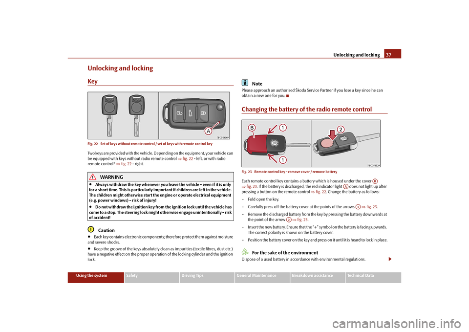
Unlocking and lockingKeyFig. 22 Set of keys without remote control / set of keys with remote control keyTwo keys are provided with the vehicle. Depending on the equipment, your vehicle can
be equipped with keys without radio remote control fig. 22 - left, or with radio
remote control* fig. 22 - right.
WARNING
Always withdraw the key whenever you leave the vehicle - even if it is only
for a short time. This is particularly important if children are left in the vehicle.
The children might otherwise start the en gine or operate electrical equipment
(e.g. power windows) - risk of injury!
Do not withdraw the ignition key from the ignition lock until the vehicle has
come to a stop. The steerin g lock might otherwise enga ge unintentionally - risk
of accident!Caution
Each key contains electronic components; therefore protect them against moisture
and severe shocks.
Keep the groove of the keys absolutely clean as impurities (textile fibres, dust etc.)
have a negative effect on the proper operation of the locking cylinder and the ignition
lock.
Note
Please approach an authorised Škoda Servic e Partner if you lose a key since he can
obtain a new one for you.Changing the battery of the radio remote controlFig. 23 Remote control key - remove cover / remove batteryEach remote control key contains a batt ery which is housed under the cover
fig. 23 . If the battery is discharged, the red in dicator light does not light up after
pressing a button on the remote control fig. 22 . Change the battery as follows:
– Fold open the key.
– Carefully press off the battery cover at the points of the arrows fig. 23 .
– Remove the discharged battery from the key by pressing the battery downwards at the point of the arrow fig. 23 .
– Insert the new battery. Ensure that the “+” symbol on the battery is facing upwards.
The correct polarity is shown on the battery cover.
– Position the battery cover on the key and press on it until it is heard to lock in place.
For the sake of the environment
Dispose of a used battery in accord ance with environmental regulations.
AB
AA
A1
A2
s43s.1.book Page 37 Thursday, May 13, 2010 1:21 PM
Page 44 of 275
Unlocking and locking43
Using the system
Safety
Driving Tips
General Maintenance
Breakdown assistance
Technical Data
Emergency unlocking of the boot lid (Combi)If there is a fault in the central lockin g, you can open the boot lid as follows:
– Fold the seat backrest forwards page 72.
– Open up the cover of the lock upwards fig. 30 .
– Move the operating lever with the aid of a narrow object e.g. screwdriver up to
the stop in the direction of arro w; the boot lid is then unlocked.
– Open the boot lid from the outside.Remote control*DescriptionYou can use the remote control:
to unlock and lock the car,
unlocking boot lid,
electrically open and close the windows.
The transmitter with the battery is housed in the handle of the remote control key. The
receiver is located in the interior of the car. The operating range of the remote control
key is approx. 10 m. But this range can be reduced if the batteries are weak.
The key has a fold-open key bit which can be used for unlocking and locking the car
manually and also for starting the engine. If a lost key is replaced or if the receiver unit has been repaired or a new unit installed,
it is then necessary for an authorised Škoda Service Partner to initialise the system.
Only after this is it possible
to again use the remote control.
Note
The remote control is automatically deacti vated when the ignition is switched on.
The operation of the remote control may temporarily be affected by interference
from transmitters close to the car and which operate in the same frequency range (e.g.
mobile phone, TV transmitter).
The battery must be replaced, ideally by an authorised Škoda Service Partner, if the
central locking or anti-theft alarm system does react to the remote control at less than
3 metres away.
If the driver door is opened, the vehi cle cannot be locked using the remote
control.
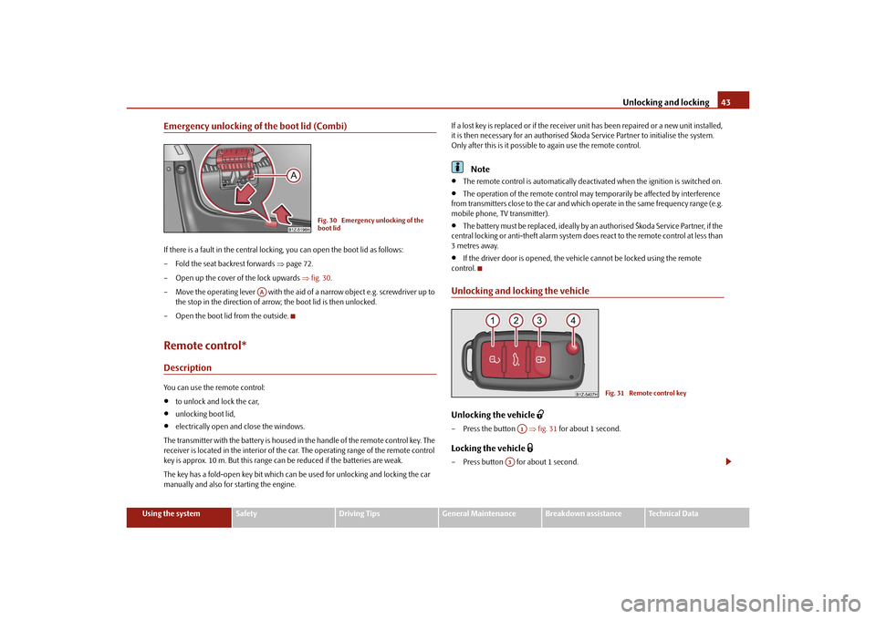
Unlocking and locking the vehicleUnlocking the vehicle
– Press the button fig. 31 for about 1 second.Locking the vehicle
– Press button for about 1 second.
Fig. 30 Emergency unlocking of the
boot lid
AA
Fig. 31 Remote control key
A1
A3
s43s.1.book Page 43 Thursday, May 13, 2010 1:21 PM
Page 112 of 275
Starting-off and Driving111
Using the system
Safety
Driving Tips
General Maintenance
Breakdown assistance
Technical Data
Releasing the handbrake– Pull the handbrake lever up slightly and at the same time press in the locking
button fig. 113 .
– Hold the button pressed and push the handbrake lever down fully .
The handbrake warning light
lights up when the handbrak e is applied, provided the
ignition is on.
A warning signal sounds and the following text appears in the display* if you have inad-
vertently driven off with the handbrake applied:
Release parking brake!
The handbrake warning is acti vated if you drive at a speed of more than 6 km/h for
more than 3 seconds.
WARNING
Please note that the handbrake must be fully released. A handbrake which
is only partially released can result in the rear brakes overheating which will
have a negative effect on the operation of the brake system - risk of accident! In
addition this can result in premature wear of the rear brake pads.
Never leave children unattended in the vehicle. The children might, for
example, release the handbrake or take the vehicle out of gear. The vehicle
might then move off - risk of accident!Caution
After the car has come to a stop, always firs t of all apply the handbrake firmly before
then additionally engaging a gear (manual gearbox) or moving the selector lever into
position P (automatic gearbox).
Rear parking aid*The parking aid provides a warning of obstacles behind the vehicle.The audible parking aid determines the di stance between the rear bumper and an
obstacle located behind the ve hicle with the aid of ultrasound sensors. The tones of
the parking aid can be adapted in th e menu of the information display* page 25.
The sensors are integrated in the rear bumper.
Range of sensors
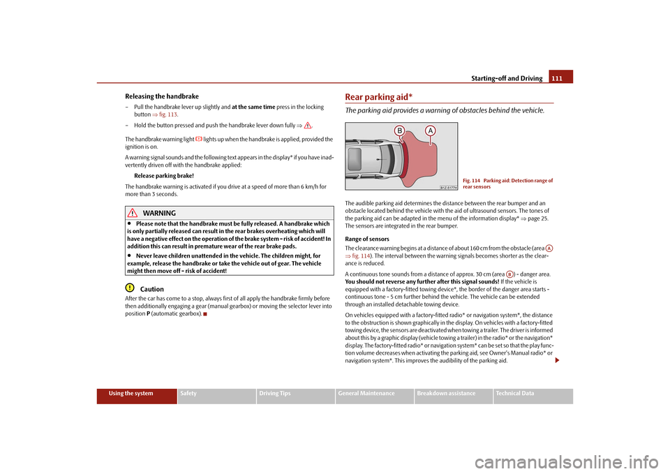
The clearance warning begins at a distance of about 160 cm from the obstacle (area
fig. 114 ). The interval between the warning signals becomes shorter as the clear-
ance is reduced.
A continuous tone sounds from a distance of approx. 30 cm (area ) - danger area.
You should not reverse any further after this signal sounds! If the vehicle is
equipped with a factory-fitted towing device*, the border of the danger area starts -
continuous tone - 5 cm further behind th e vehicle. The vehicle can be extended
through an installed deta chable towing device.
On vehicles equipped with a factory-fitted radio* or navigation system*, the distance
to the obstruction is shown graphically in the display. On vehicles with a factory-fitted
towing device, the sensors are deactivated when towing a trailer. The driver is informed
about this by a graphic display (vehicle towing a trailer) in the radio* or the navigation*
display. The factory-fitted radio* or navigati on system* can be set so that the play func-
tion volume decreases when activating the parking aid, see Owner's Manual radio* or
navigation system*. This improves the audibility of the parking aid.
Fig. 114 Parking aid: Detection range of
rear sensors
AA
AB
s43s.1.book Page 111 Thursday, May 13, 2010 1:21 PM
Page 117 of 275
Automatic gearbox
116
Automatic gearboxAutomatic gearbox*Information for driving with the 6-speed automatic gearbox*
Your car is equipped with a conv entional 6-speed automatic gearbox.The maximum speed is reached in the 5th gear. The 6th gear serves as an economic
driving programme, which is intended to redu ce the fuel consumption. Shifting up and
down through the gears is performed automa tically. You can also, however, switch the
gearbox over into the Tiptronic mode. This mode makes it possible for you to also shift
gears manually page 120.Starting-off and Driving– Depress the brake pedal fully and keep it depressed.
– Press the Shiftlock button (button in ha ndle of the selector lever), move the
selector lever into the desired position, e.g. D page 118, and then release the
Shiftlock button.
– Wait a moment until the gearbox has shif ted (a slight engagement nudge can be
felt).
– Release the brake pedal and depress the accelerator .Stop– The selector lever position N does not have to be selected when stopping just for
a short time, such as at a cross roads. It is absolutely sufficient to hold the stopped
vehicle stationary by depressing the foot brake. The engine can, however, be
allowed just to idle.Parking– Depress the brake pedal and hold it depressed.
– Apply the handbrake firmly.
– Press and Shiftlock button in the selector lever, move the selector lever to P and
then release the Shiftlock button. The engine can only be
started when the selector lever is in position P or N
page 108.
It is sufficient to engage selector lever position P when parking on a flat surface. When
parking on a slope you should first apply the handbrake firmly and then move the
selector lever into position P. This is to ensure that there is no excessive pressure acting
on the lock mechanism and that it is easier to subsequently move the selector lever out
of position P.
If the selector lever position N is selected by accident while driving it is first necessary
to release pressure on the accelerator pedal and wait for idling speed of the engine to
be reached before engaging a driv e position in the selector lever.
WARNING
Do not depress the accelerator when changing the position of the selector
lever if the car is stationary and the engine is running - risk of accident!
Never move the selector lever into position R or P when driving - risk of an
accident!
When the engine is running and the vehi cle is stationary, it is necessary to
hold the car with the brake pedal in all the positions of the selector lever (except
P and N) since the power transmission is never completely interrupted, also not
when the engine is idling - the vehicle creeps.
Information for driving with the automatic gearbox DSG*
The abbreviation DSG means Direct shift gearbox (Direct shift gearbox). Two independent clutches are needed for the power transmission between the engine
and the gearbox. These replace the torque converter of the conventional automatic
gearbox. Their shifting is matched in such a way that there are no jerks when shifting
the gear and the power transmission of the engine to the front wheels is not inter-
rupted. Shifting up and down through the gears is performed automatically. You can
also, however, switch the gearbox over into the Tiptronic mode. This mode makes it
possible for you to also shift gears manually page 120.
s43s.1.book Page 116 Thursday, May 13, 2010 1:21 PM
Page 118 of 275
Automatic gearbox117
Using the system
Safety
Driving Tips
General Maintenance
Breakdown assistance
Technical Data
Starting-off and Driving– Depress the brake pedal fully and keep it depressed.
– Press the Shiftlock button (button in ha ndle of the selector lever), move the
selector lever into the desired position, e.g. in D, and then release the Shiftlock
button.
– Release the brake pedal and depress the accelerator .Stop– The selector lever position N does not have to be selected when stopping just for
a short time, such as at a cross roads. It is absolutely sufficient to hold the stopped
vehicle stationary by depressing the foot brake. The engine can, however, be
allowed just to idle.Parking– Depress the brake pedal and hold it depressed.
– Apply the handbrake firmly.
– Press and Shiftlock button in the selector lever, move the selector lever to P and
then release the Shiftlock button.
The engine can only be started when the selector le ver is in position P or N
page 108. At temperatures below -10 °C the engine can only be started in the
selector lever position P .
It is sufficient to engage selector lever position P when parking on a flat surface. When
parking on a slope you should first apply the handbrake firmly and then move the
selector lever into position P. This is to ensure that there is no excessive pressure acting
on the lock mechanism and that it is easier to subsequently move the selector lever out
of position P.
If the selector lever position N is selected by accident while driving it is first necessary
to release pressure on the accelerator pedal and wait for idling speed of the engine to
be reached before engaging a drive position in the selector lever.
WARNING
Do not depress the accelerator when changing the position of the selector
lever if the car is stationary and the engine is running - risk of accident!
Never move the selector lever into position R or P when driving - risk of an
accident!
If you are stopping at a hill (downhill section), never try to hold the car
stationary with the gear engaged by mean s of the “accelerator”, this means by
letting the clutch slip. This can lead to ov erheating of the clutch. If there is a risk
of overheating of the clutch due to overlo ad, the clutch is opened automatically
and the vehicle rolls backward - risk of accident!
If yo u m us t s to p a t a sl ope , d e pre s s a nd ho ld t he b ra ke pe d a l , s o t ha t y ou c a n
prevent the vehicle from rolling back.Caution
The double clutch on the automatic gear box DSG is equipped with an overload
protection. If you make use of the uphill func tion on a vehicle which is stationary or
driving slowly uphill, it will result in an increase of thermal stress of the clutches.
An overheating of the clutches can be detect ed by the flashing of the selector level
indicator and the “jerk” of the clutches, finally the clutches are opened. The power
transmission from the engine to the front whee ls is interrupted and as a result of this
the vehicle can no longer be driven. If th e clutch opens automatically, depress the
brake pedal, wait a few seconds and only then continue driving.
s43s.1.book Page 117 Thursday, May 13, 2010 1:21 PM
Page 131 of 275
Communication
130
the handwheel. You can select the numbers 0 - 9, the symbols +,
, # and the func-
tions Delete, Call, Cancel .
Call register
In the menu point Call register, you can select the following menu points:
Missed calls
Received calls
Last calls
Voice mailbox
In the menu Voice mailbox , it is possible to set the number of the voice mailbox and
then dial the number.
Bluetooth
In the menu Bluetooth you can select the following menu points:
User - the overview of the stored users
New user - Search for new telephones which are in the reception range
Visibility - Switching on the visibility of the telephone unit for other devices
Media player
Active device
Paired devices
Search
Phone name - the possibility to change the name of the telephone unit (pre-set
SKODA UHV)
Settings
In the menu Settings you can select the following menu points:
Phone book
Update
List
Surname
First name
Ring tone Back
Return in the basic menu of the telephone.
Voice controlIntroductionThe period, in which the telephone system is ready to receive voice commands and
carry out the voice commands, is called DIALOGUE. The system gives audible feedback
and guides you if necessary th
rough the relevant functions.
Switch on voice control (dialogue)
You can start the dialogue at any time by briefly pressing the PTT button
on the
adapter* page 128, fig. 123 or on the multifunction steering wheel* page 128.
If the system does not recognise your command, it repeats the first part of the aid and
thus a new entry is possible. After the 2nd error the system repeats the second part of
the aid. After the 3rd error the answer “ Cancel” is given and the dialogue is ended.
Switching off voice control (dialogue)
You can end the dialogue at any time by briefly pressing the PTT button
on the
adapter* page 128, fig. 123 or on the multifunction steering wheel* page 128. If
the system expects a voice command, you can end the dialogue with the command
CANCEL .
Only the message just repeated can be ended by pressing the PTT button during the
message and thus it is possible to pronounce the expected command sooner.
When receiving an incoming call, the dialog ue is immediately interrupted and you can
accept the call by pressing the button
on the multifunction steering wheel* or by
pressing the button for receiving a call directly on your telephone.
Optimum understanding of the voice commands depends on the following
factors:
Speak with a normal tone of voice withou t intonation and excessive voice pauses.
Avoid insufficient articulation.
Close the doors, windows and sliding roof, in order to reduce or stop disturbing
exterior noise.
s43s.1.book Page 130 Thursday, May 13, 2010 1:21 PM
Page 138 of 275
Communication137
Using the system
Safety
Driving Tips
General Maintenance
Breakdown assistance
Technical Data
Signal settings
Ring tone
Volume
Phone settings
Select operator
Automatic
Manual
Network mode
Off time
SIM mode - applies to telephones with the rSAP profile in which two SIM cards
can be inserted - there is the possibility to select which SIM card may be connected
with the hands-free system and the possibility to select the name for the SIM card.
SIM mode 1
SIM mode 2
GPRS - You can ask a network provider about the settings of the access point for an
internet connection
Switch off ph. - switching off the telephone unit (telephone remains connected)
Back
Return in the main menu of the information display.
Voice controlIntroductionThe period, in which the telephone system is ready to receive voice commands and
carry out the voice commands, is called DI ALOGUE. The system gives audible feedback
and guides you if necessary through the relevant functions.
The volume can be changed at any time with the control button of the radio* or the
navigation system* or with the buttons on the multifunction steering wheel*. Switch on voice control (dialogue)
You can start the dialogue at any time
by briefly pressing the PTT button
on the
multifunction st eering wheel* page 134.
If the system does not recognise your command, it repeats the first part of the aid and
thus a new entry is possible. After the 2nd error the system repeats the second part of
the aid. After the 3rd error the answer “ Procedure cancelled” is given and the dialogue
is ended.
Switching off voice control (dialogue)
You can end the dialogue at an y time by briefly pressing the button on the multifunc-
tion steering wheel* page 134. If the system expects a voice command, you can end
the dialogue with the command CANCEL.
Only the message just repeated can be ended by pressing the PTT button during the
message and thus it is possible to pronounce the expected command sooner.
The dialogue of the incoming call is immediately interrupted and you can accept the
call by pressing the button
on the multifunction steering wheel*.
Optimum understanding of the voice commands depends on the following
factors:
Speak with a normal tone of voice withou t intonation and excessive voice pauses.
Avoid insufficient articulation.
Close the doors, windows and sliding roof, in order to reduce or stop disturbing
exterior noise.
It is recommended to speak louder at higher speeds, so that the tone of your voice
is louder than the increased surrounding noise.
During the dialogue avoid additional noise in the vehicle, e.g. simultaneously
talking occupants.
Do not speak, if the system makes an announcement.
The microphone for voice control is inserted in the moulded headliner and
directed to the driver and front passenger. Therefore the driver and the front passenger
can operate the equipment.
s43s.1.book Page 137 Thursday, May 13, 2010 1:21 PM
Page 174 of 275
Intelligent Technology173
Using the system
Safety
Driving Tips
General Maintenance
Breakdown assistance
Technical Data
one wheel per axle was changed.
Basic setting of the system
After changing the tyre inflation pressures, after changing one or several wheels, the
position of a wheel on the vehicle (e.g. exch anging the wheels between the axles) or
when the warning light lights up while drivin g, a basic setting of the system must be
carried out as follows.
Inflate all tyres to the specified inflation pressure page 208.
Switch on the ignition.
Press button page 172, fig. 151 for more than 2 seconds. While pressing
the button, the warning light
lights up. At the same time the memory of the system
is erased and the new calibration is started, which is confirmed with an audible signal
and then the warning light
goes out.
If the warning light
does not go out after the basic setting, there is a fault in the
system. Have the vehicle inspected by your nearest specialist garage.
Warning light
lights up
If the tyre inflation pressure of at least one wheel is insufficiently inflated in comparison
to the stored basic value, the warning light
lights up.
Warning light
flashes
If the warning light flashes, there is a system fault. Have the vehicle inspected by your
nearest specialist garage.
WARNING
When the warning light
lights up, immediately reduce the speed and
avoid sudden steering and brake manoeuvr es. Please stop the vehicle without
delay at the nearest possible stop and in spect the tyres and their inflation pres-
sures.
The driver is responsible for the correct tyre inflation pressures. For this
reason, the tyre inflation pressu res must be checked regularly.
Under certain circumstances (e.g. sporty style of driving, wintry or unpaved
roads) the warning light
can be delayed or does not light up at all.
The tyre pressure monitoring system does not take away the responsibility
from the driver for the correct tyre inflation pressure.
Note
The tyre pressure monitoring system:
does not replace the regular tyre inflatio n pressure control, because the system
cannot detect an even pressure loss,
cannot warn in case of very rapid tyre inflation pressure loss, e.g. in case of sudden
tyre damage. In this case ca refully bring the vehicle to a standstill without sudden
steering movements and without sharp braking.
In order to ensure a proper functioning of the tyre inflation pressure-control
system, it is necessary to carry out the ba sic setting again every 10 000 km or 1x a
year.
Diesel particle filter* (diesel engine)In the diesel particle filter the resu lting soot particles are collected and
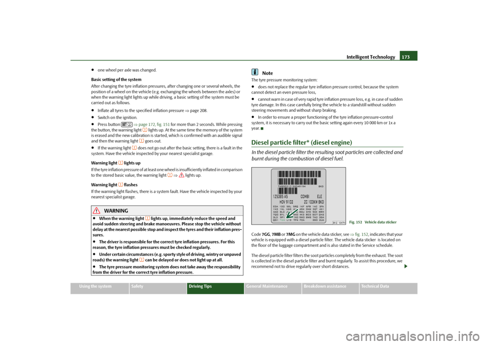
burnt during the combustion of diesel fuel.Code 7GG, 7MB or 7MG on the vehicle data sticker, see fig. 152 , indicates that your
vehicle is equipped with a diesel particle fi lter. The vehicle data sticker is located on
the floor of the luggage compartment and is also stated in the Service schedule.
The diesel particle filter filters the soot particles completely from the exhaust. The soot
is collected in the diesel particle filter and burnt regularly. To assist this procedure, we
recommend not to drive regu larly over short distances.
Fig. 152 Vehicle data sticker
s43s.1.book Page 173 Thursday, May 13, 2010 1:21 PM
Page 235 of 275
Fuses and light bulbs
234
– In order to reinstall the cover, first of all insert one part of the cover starting on the
side facing the marking. Then press the cove r closed on the side facing the fog light.
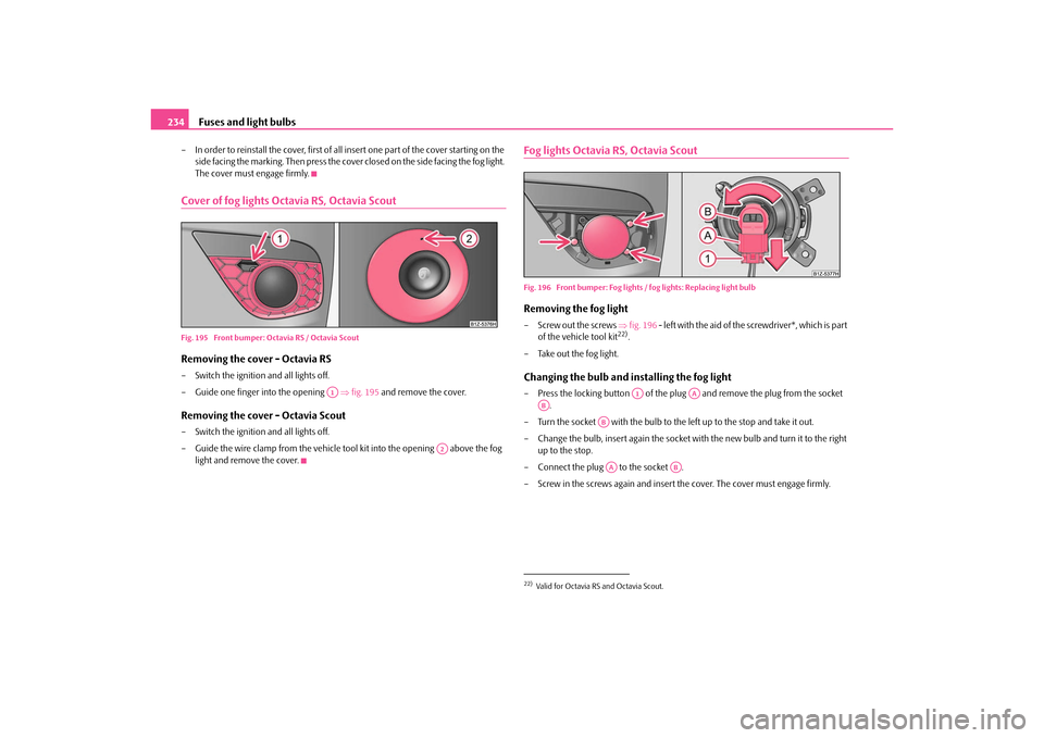
The cover must engage firmly.Cover of fog lights Octavia RS, Octavia ScoutFig. 195 Front bumper: Octavia RS / Octavia ScoutRemoving the cover - Octavia RS– Switch the ignition and all lights off.
– Guide one finger into the opening fig. 195 and remove the cover.Removing the cover - Octavia Scout– Switch the ignition and all lights off.
– Guide the wire clamp from the vehicle tool kit into the opening above the fog
light and remove the cover.
Fog lights Octavia RS, Octavia ScoutFig. 196 Front bumper: Fog lights / fog lights: Replacing light bulbRemoving the fog light–Screw out the screws fig. 196 - left with the aid of the screwdriver*, which is part
of the vehicle tool kit
22).
– Take out the fog light.
Changing the bulb and installing the fog light– Press the locking button of the plug and remove the plug from the socket
.
– Turn the socket with the bulb to the left up to the stop and take it out.
– Change the bulb, insert again the socket wi th the new bulb and turn it to the right
up to the stop.
– Connect the plug to the socket .
– Screw in the screws again and insert the cover. The cover must engage firmly.
A1
A2
22)Valid for Octavia RS and Octavia Scout.
A1
AA
AB
ABAA
AB
s43s.1.book Page 234 Thursday, May 13, 2010 1:21 PM