check engine light SKODA OCTAVIA 2010 2.G / (1Z) Technical Change
[x] Cancel search | Manufacturer: SKODA, Model Year: 2010, Model line: OCTAVIA, Model: SKODA OCTAVIA 2010 2.G / (1Z)Pages: 22, PDF Size: 0.95 MB
Page 2 of 22

Introduction1
IntroductionThis supplement replaces the Owner's manual OCTAVIA Edition 05.10 referred to in
the following as the Owner's manual.
The information given in this supplement takes preference over the information in the
Owner's manual.
Special equipment is marked with the symbol *.
We wish you a good journey
Škoda Auto a.s.Safelock
Note
When activating the Safelock function after you lock the vehicle, the message CHECK
SAFELOCK will appear in the display of the inst rument cluster. In vehicles equipped
with a MAXIDOT info display*, the message Check deadlock! Owner's manual!
(Observe SAFE locking! Car documentation!) appears. Windscreen wipersThe washing nozzles of the windscreen washer system are heated during engine
running and when the outdoor temperature is less than +10 °C * .
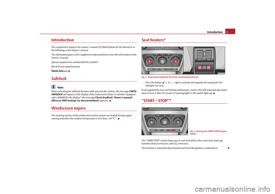
Seat heaters*Fig. 1 Dash panel: Regulator for front seat heating front/rear– Press the button
fig. 1 - right to activate and regulate the heating for the
left/right rear seat.
If you regulate the rear seat heating at full power - level 3, this will automatically switch
back to level 2 after 10 minutes (2 wa rning lights in the switch light up).
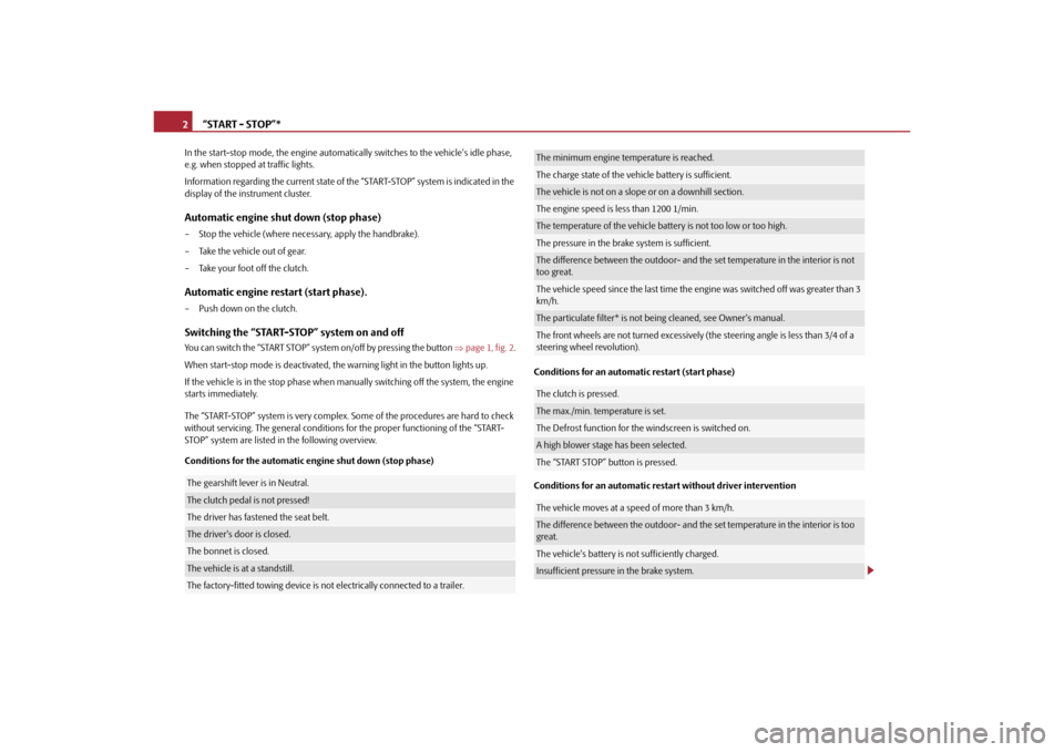
“START - STOP”*The “START-STOP” system helps you to save fuel while at the same time reducing
harmful exhaust emissions and CO
2 emissions.
The function is automatically activated ea ch time the ignition is switched on.
Fig. 2 Dash panel: START-STOP System
button
s1ec.5.book Page 1 Friday, September 24, 2010 10:46 AM
Page 3 of 22

“START - STOP”*
2
In the start-stop mode, the engine automatica lly switches to the vehicle's idle phase,
e.g. when stopped at traffic lights.
Information regarding the current state of th e “START-STOP” system is indicated in the
display of the instrument cluster.Automatic engine shut down (stop phase)– Stop the vehicle (where nece ssary, apply the handbrake).
– Take the vehicle out of gear.
– Take your foot off the clutch.Automatic engine restart (start phase).– Push down on the clutch.Switching the “START-STOP” system on and offYou can switch the “START STOP” system on/off by pressing the button page 1, fig. 2 .
When start-stop mode is deactivated, the warning light in the button lights up.
If the vehicle is in the stop phase when ma nually switching off the system, the engine
starts immediately.
The “START-STOP” system is very complex. Some of the procedures are hard to check
without servicing. The general conditions for the proper functioning of the “START-
STOP” system are listed in the following overview.
Conditions for the automatic engine shut down (stop phase) Conditions for an automatic restart (start phase)
Conditions for an automatic restart without driver interventionThe gearshift lever is in Neutral.The clutch pedal is not pressed!The driver has fastened the seat belt.The driver's door is closed.The bonnet is closed.The vehicle is at
a standstill.The factory-fitted towing device is no t electrically connected to a trailer.
The minimum engine temperature is reached.The charge state of the vehicle battery is sufficient.The vehicle is not on a slope or on a downhill section.The engine speed is less than 1200 1/min.The temperature of the vehicle battery is not too low or too high.The pressure in the brake system is sufficient.The difference between the outdoor- and the set temperature in the interior is not
too great.The vehicle speed since the last time the engine was switched off was greater than 3
km/h.The particulate filter* is not be ing cleaned, see Owner's manual.The front wheels are not turned excessively (t he steering angle is less than 3/4 of a
steering wheel revolution).The clutch is pressed.The max./min. temperature is set.The Defrost function for the windscreen is switched on.A high blower stage has been selected.The “START STOP” button is pressed.The vehicle moves at a speed of more than 3 km/h.The difference between the outdoor- and the set temperature in the interior is too
great.The vehicle's battery is not sufficiently charged.Insufficient pressure in the brake system.
s1ec.5.book Page 2 Friday, September 24, 2010 10:46 AM
Page 7 of 22

Tyre repair kit*
6
•
Check the tyre inflation pressure after driving 10 minutes.
•
Sealant is hazardous to heath. Remove immediately if it comes into contact
with the skin.For the sake of the environment
Used or aged sealant must be disposed of in accordance with environmental protec-
tion regulations.
Note
•
Observe the manufacturer's usage instructions for the tyre repair kit.
•
You can purchase a new bottle of sealant from the range of the Škoda original
accessories.
•
Change the wheel that was repaired using the tyre repair kit or consult a specialist
garage about possibilities for getting repairs done.
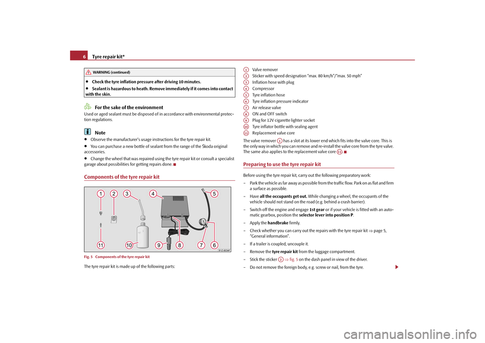
Components of the tyre repair kitFig. 5 Components of the tyre repair kitThe tyre repair kit is made up of the following parts: Valve remover
Sticker with speed designation “max. 80 km/h”/“max. 50 mph”
Inflation hose with plug
Compressor
Tyre inflation hose
Tyre inflation pressure indicator
Air release valve
ON and OFF switch
Plug for 12V cigarette lighter socket
Tyre inflator bottle with sealing agent
Replacement valve core
The valve remover has a slot at its lower end which fits into the valve core. This is
the only way in which you can remove and re-i nstall the valve core from the tyre valve.
The same also applies to the replacement valve core .
Preparing to use the tyre repair kitBefore using the tyre repair kit, carry out the following preparatory work:
– Park the vehicle as far away as possible from the traffic flow. Park on as flat and firm a surface as possible.
–Have all the occupants get out. While changing a wheel, the occupants of the
vehicle should not stand on the ro ad (e.g. behind a crash barrier).
– Switch off the engine and engage 1st gear or if your vehicle is fitted with an auto-
matic gearbox, position the selector lever into position P .
– Apply the handbrake firmly.
– Check whether you can carry out the repairs with the tyre repair kit page 5,
“General information”.
– If a trailer is coupled, uncouple it.
– Remove the tyre repair kit from the luggage compartment.
– Stick the sticker fig. 5 on the dash panel in view of the driver.
– Do not remove the foreign body, e.g. screw or nail, from the tyre.
WARNING (continued)
A1A2A3A4A5A6A7A8A9A10A11
A1
A11
A2
s1ec.5.book Page 6 Friday, September 24, 2010 10:46 AM
Page 9 of 22

Tow-starting and towing vehicle
8
Check after driving for 10 minutesCheck the tyre inflation pressu re after driving 10 minutes.If the tyre inflation pressure is 1.3 bar or less:–Do not drive the vehicle! You cannot properly seal wi th tyre with the breakdown
kit.
– Obtain professional assistance.If the tyre inflation pressure is 1.3 bar or more:– Adjust the tyre inflation pressure to the correct value (see inside of fuel filler cap).
– Continue driving carefully to the nearest specialist garage at a maximum speed of 80 km/h (50 mph). Tow-starting and towing vehicleGeneral
Caution
Do not push or two the vehicle to start the engine - likely engine damage! In vehicles
with catalytic converters, fuel may get into the catalytic converter where it may ignite.
This results in the catalytic converter overheating and being destroyed. To help start
the engine, you can use a battery from another vehicle, see Owner's manual.Electric fusesFuse assignment in engine compartment
Fuse assignment in the dash panel
No.
Power consumer
Amperes
F6
Not assigned
F9
Not assigned
No.
Power consumer
Amperes
4
Heating, air conditioning, reversing lights, interior rear
view mirror dimming, telephone preinstallation, START
STOP button
5
6
Instrument cluster, Control unit for automatic gearbox,
Control unit for electromechani cal power steering, Parking
aid; Haldex clutch, “START ST OP” relay, DC/DC voltage sta-
biliser
5
28
Radio
15
39
Instrument cluster, windshield wiper lever and turn signal
light lever
5
48
Phone
5
s1ec.5.book Page 8 Friday, September 24, 2010 10:46 AM