ESP SKODA OCTAVIA 2012 2.G / (1Z) User Guide
[x] Cancel search | Manufacturer: SKODA, Model Year: 2012, Model line: OCTAVIA, Model: SKODA OCTAVIA 2012 2.G / (1Z)Pages: 222, PDF Size: 13.52 MB
Page 56 of 222
The rear window is wiped once automatically if the windscreen wipers are onwhen reverse gear is selected.
Automatic rear window wiping can be activated/deactivated in the Infotain-
ment » operating instructions for Infotainment , chapter Setting vehicle systems
(CAR button) .
Top up with windscreen wiper fluid » page 176.WARNING■
Properly maintained windscreen wiper blades are essential for clear visibility
and safe driving » page 56.■
Do not use the windscreen washer system at low temperatures, without
heating the windscreen beforehand. Otherwise the window cleaner could
freeze on the windscreen and restrict the view to the front.
■
Automatic wiping in rain only operates as a support. The driver is not re-
leased from the responsibility to set the function of the windscreen wipers
manually depending on the visibility conditions.
■
Replace the windscreen wiper blades once or twice a year for safety rea-
sons. These can be purchased from a ŠKODA Partner.
CAUTION
■ In cold temperatures and during the winter, check before the journey or before
switching on the ignition that the wiper blades are not frozen to the windscreen. If the windscreen wipers are switched on when the blades are frozen to the
windscreen, this may damage both the blades and windscreen wiper motor!■
If the ignition is switched off while the windscreen wipers are switched on, the
windscreen wipers will continue wiping in the same mode after the ignition is
turned back on. The windscreen wipers could freeze up in cold temperatures be- tween the time the ignition was turned off and when it was turned back on again.
■
Carefully detach frozen wiper blades from the front or rear window.
■
Remove snow and ice from the windscreen wipers before driving.
■
If the windscreen wipers are handled carelessly, there is a risk of damage to the
windscreen.
■
The ignition must not be switched on if the front windscreen wiper arms are fol-
ded out. The wiper blades would move back into their rest position and while do-
ing so damage the paintwork of the bonnet.
Note■ The windscreen wiper switches off each time the ignition switches off for the
third time. This counteracts an early fatigue of the wiper rubbers.■
If there is an obstacle on the windscreen, the wiper will try to push away the
obstacle. The wiper stops automatically after 5 attempts to eliminate the obsta-
cle, in order to avoid a damage to the wiper. Remove the the obstacle and switch
the wiper on again.
■
The rear window wiper only operates if the boot lid is closed.
■
The windscreen washer nozzles for the windscreen are heated when the en-
gine is running and the outside temperature is less than approx. +10 °C.
■
Keep the wiper blades clean. The wiper blades can become soiled with wax resi-
dues after washing in automatic vehicle wash systems for example » page 160.
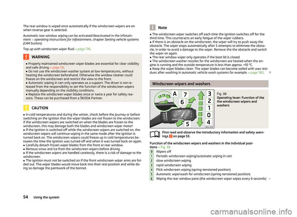
Windscreen wipers and washers
Fig. 38
Operating lever: Function of the
the windscreen wipers and
washers
First read and observe the introductory information and safety warn-
ings on page 53.
Function of the windscreen wipers and washers in the individual posi-
tions » Fig. 38
Wipers off
Periodic windscreen wiping/automatic wiping in rain slow windscreen wipingrapid windscreen wiping
Flick windscreen wiping (spring-tensioned position)
Automatic wipe/wash for windscreen (spring-tensioned position) Wiping the rear window pane (the windscreen wiper wipes every 6 seconds)
012345654Using the system
Page 66 of 222
›Push the lever A
» Fig. 50 and fold the seat backrest completely forwards.
Folding backwards›
Hold the rear outer seat belt
C
» Fig. 50 against the side trim panel.
›
Then push the seat backrest back into the upright position until the securing
knob
A
clicks into place – check by pulling on the seat backrest » .
›
Make sure that the red pin
B
is hidden.
WARNING■
The belts and the belt locks must be in their original position after folding
back the seat backrests – they must be ready to use.■
The seat backrests must be securely interlocked in position so that no ob-
jects in the luggage compartment can slide into the passenger compartment if
there is sudden braking – risk of injury.
■
Ensure that the rear seat backrests are properly engaged. It is only then that
the three-point seat belt for the middle seat can reliably fulfil its function.
CAUTION
Ensure that the seat belts are not damaged when operating the seat backrests. Under no circumstances must the rear seat belts be jammed by the folded back
seat backrests.
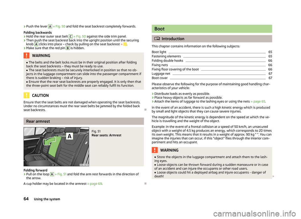
Rear armrest
Fig. 51
Rear seats: Armrest
Folding forward
›
Pull on the loop
A
» Fig. 51 and fold the arm rest forwards in the direction of
the arrow.
A cup holder may be located in the armrest » page 69.
Boot
Introduction
This chapter contains information on the following subjects:
Boot light
65
Fastening elements
65
Folding double hooks
66
Fixing nets
66
Fixing floor covering of the boot
66
Luggage net
67
Boot cover
67
Please observe the following for the purpose of maintaining good handling char-
acteristics of your vehicle:
›
Distribute loads as evenly as possible.
›
Place heavy objects as far forward as possible.
›
Attach the items of luggage to the lashing eyes or using the nets » page 65.
In the event of an accident, there is such a high kinetic energy which is produced
by small and light objects that they can cause severe injuries.
The magnitude of the kinetic energy is dependent on the speed at which the ve-
hicle is travelling and the weight of the object.
Example: In the event of a frontal collision at a speed of 50 km/h, an unsecured
object with a weight of 4.5 kg produces an energy, which corresponds to 20 times
its own weight. This means that it results in a weight of approx. 90 kg “ ”. You can imagine the injuries that can occur, if this “object” flies through the interior com-partment and hits an occupant.
WARNING■ Store the objects in the luggage compartment and attach them to the lash-
ing eyes.■
Loose objects can be thrown forward during a sudden manoeuvre or in case
of an accident and can injure the occupants or other road users.
■
Loose objects could hit a deployed airbag and injure occupants - danger of
death!
64Using the system
Page 85 of 222
Heating
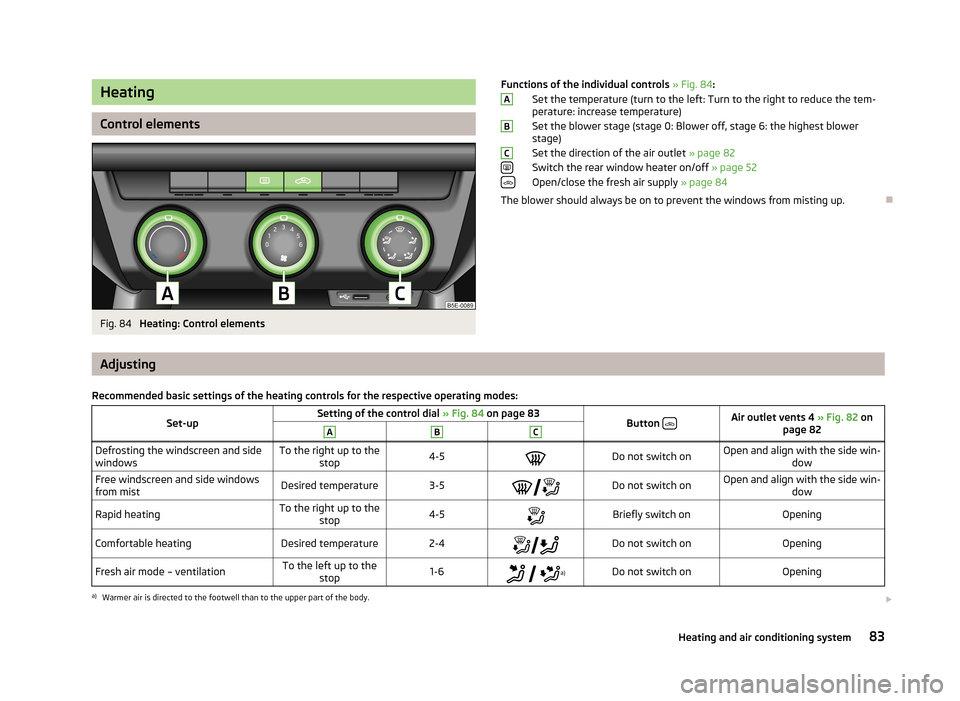
Control elements
Fig. 84
Heating: Control elements
Functions of the individual controls » Fig. 84 :
Set the temperature (turn to the left: Turn to the right to reduce the tem-
perature: increase temperature)
Set the blower stage (stage 0: Blower off, stage 6: the highest blower
stage)
Set the direction of the air outlet » page 82
Switch the rear window heater on/off » page 52
Open/close the fresh air supply » page 84
The blower should always be on to prevent the windows from misting up.ABC
Adjusting
Recommended basic settings of the heating controls for the respective operating modes:Set-upSetting of the control dial » Fig. 84 on page 83Button Air outlet vents 4
» Fig. 82 on
page 82ABCDefrosting the windscreen and side
windowsTo the right up to the stop4-5Do not switch onOpen and align with the side win- dowFree windscreen and side windows
from mistDesired temperature3-5 Do not switch onOpen and align with the side win-
dowRapid heatingTo the right up to thestop4-5Briefly switch onOpeningComfortable heatingDesired temperature2-4Do not switch onOpeningFresh air mode – ventilationTo the left up to the
stop1-6
a)Do not switch onOpeninga)
Warmer air is directed to the footwell than to the upper part of the body.
83Heating and air conditioning system
Page 87 of 222
NoteThe warning light in the button lights after activation, even if not all of the
conditions for the function of the cooling system have been met » page 84, Intro-
ductory information . By lighting up of the warning light in the button, the opera-
tional readiness of the cooling system is signalled.
Setting the air conditioning system
Recommended basic settings of the control elements of the air conditioning system for the respective operating modes:Set-upSetting of the control dial » Fig. 85 on page 84Button » Fig. 85 on page 84Air outlet vents 4 » Fig. 82
on page 82ABCDefrost/defog windscreen and
side windows a)Desired tempera-
ture4-6Automatically
switched on b)Do not switch onOpen and align with the side
windowRapid heatingTo the right up tothe stop4-6Switched offBriefly switch onOpeningComfortable heatingDesired tempera-
ture1-4
Switched offDo not switch onOpeningRapid coolingTo the left up to
the stopbriefly 6, then 2 - 3ActivatedAutomatically switched
onc)OpeningComfortable coolingDesired tempera-
ture1-3
d)ActivatedDo not switch onOpeningFresh air mode – ventilationTo the left up to
the stopDesired position
d)Switched offDo not switch onOpeninga)
We recommend that you do not use this setting in countries with high humidity levels. This can result in heavy cooling of the window glass and the following fogging from outside.
b)
Automatic activation can be switched off by pressing the button
» Fig. 85 on page 84.
c)
Automatic activation can be switched off by pressing the button
» Fig. 85 on page 84.
d)
Warmer air is directed to the footwell than to the upper part of the body.
We recommend that you leave the air outlet vents 3 » Fig. 82 on page 82 in the
opened position.
Recirculated air mode
Recirculated air mode prevents polluted air outside the vehicle from getting into the vehicle, for example when driving through a tunnel or when standing in a
traffic jam.
Switching on/off›
Press the button and the warning light underneath the button illuminates.
85Heating and air conditioning system
Page 89 of 222
Switch automatic mode on/off » page 87
Switch the cooling system on/off » page 87
Note
The interior temperature sensor is located between the buttons and SETUP.
Do not stick anything on or cover the sensor, otherwise it could have an unfav-
ourable effect on the Climatronic.
Automatic mode
Automatic mode works in three modes - weak, medium, and intensive.
Information on the setting » Bedienungsanleitung Infotainment, chapter Addi-
tional functions (CAR button) .
Switching on
›
Set the temperature between +16 °C and +29 °C using the control dials
A
and
C
» Fig. 86 on page 86.
›
Press the button AUTO and the indicator light in the button illuminates.
Switching off
›
Press any button for the air distribution or increase/reduce the blower speed.
After the Climatronic is switched on, it works in the last selected mode. The currently selected mode is displayed in the Infotainment display.Climatronic is set to the medium setting by default.
Note
We recommend that you adjust the air outlet vents 3 and 4 » Fig. 82 on page 82,
so that the air flow is directed slightly upwards.
Switch cooling system on/off
›
Press the button and the indicator light in the button illuminates.
›
Pressing the button
again switches off the cooling system - the indicator
light in the button goes out.
After the cooling system is switched off, only the ventilation function remains ac-
tive whereby the minimum temperature that can be reached is the outside tem-
perature.
AUTOSetting temperature
The interior temperature for the left and right side can be set separately or to-
gether.
For both sides›
Turn the control dial
A
» Fig. 86 on page 86 to the left or right to increase or
decrease the temperature.
The warning light in the button DUAL
goes out.
For the right side
›
Turn the control dial
C
» Fig. 86 on page 86 to the left or right to increase or
decrease the temperature.
The indicator light lights up in the DUAL
button.
If the indicator light in the button DUAL
is illuminated, the temperature for both
sides cannot be set with the control dial
A
. This function can be restored by
pressing the button DUAL. The warning light in the button goes out.
The interior temperature can be set between +16 ℃ and +29 ℃. The interior tem-
perature is regulated automatically within this range.
If a temperature lower than +16 ℃ is selected, a blue symbol lights up on the con-
trol dial.
If a temperature higher than +29 ℃ is selected, a red symbol lights up on the con-
trol dial.
At both end positions, Climatronic runs at maximum cooling/heating output and
the temperature is automatically not regulated.
CAUTION
Lengthy and uneven distribution of the air flow out of the vents (especially
around the feet) and large differences in temperature, for example, when getting
out of the vehicle, can cause susceptible individuals to catch a cold.
Automatic recirculated air mode
Recirculated air mode largely prevents polluted air from outside the vehicle get- ting into the vehicle, for example, when driving through a tunnel or when stand-
ing in a traffic jam.
87Heating and air conditioning system
Page 90 of 222
If a considerable increase in concentration of pollutants is recognised by the air
quality sensor, recirculated air mode will temporarily be switched off.
If the concentration of pollutants decreases to the normal level, the air distribu-
tion control is automatically switched off so that fresh air can be guided into the
vehicle interior.
In recirculated air mode air is sucked out of the interior of the vehicle and then
fed back into the interior. When the automatic air distribution control is switched on, an air quality sensor measures the concentration of pollutants in the drawn inair.
If the air quality sensor does not switch on automatic recirculated air mode when there is an unpleasant smell, you can switch in on manually.
Switching on/off›
Press the button and the warning light underneath the button illuminates.
›
Press the button again, the warning light underneath the button goes out,
where necessary press the button AUTO.
You can also switch the system on/off in he Infotainment » Bedienungsanleitung
Infotainment, chapter Setting vehicle systems (CAR button) .
WARNINGDo not leave recirculated air mode on over a longer period of time, as “stale”
air can cause fatigue of the driver and passengers, reduce attention levels and
also cause the windows to mist up. The risk of having an accident increases.
Switch off recirculated air mode as soon as the windows start to mist up.
Note
■ If the windscreen mists up, press the button . Press the button AUTO when
the windscreen is demisted.■
The automatic air distribution control operates only if the outside temperature
is higher than approx. 2 °C.
Controlling blower
The blower stage can be manually adapted to suit your particular needs.
›
Turn the control dial
B
» Fig. 86 on page 86 to the left or right to increase or
decrease the blower speed.
If the blower speed is reduced to a minimum, Climatronic is switched off.
The set blower speed is displayed in the control dial B when the respective num-
ber of warning lights come on.WARNING■ “Stale air” may result in fatigue in the driver and occupants, reduce attention
levels and also cause the windows to mist up. The risk of having an accident
increases.■
Do not switch off the Climatronic system for longer than necessary.
■
Switch on the Climatronic system as soon as the windows mist up.
Defrosting windscreen
Switching on/off
›
Press the button
» Fig. 86 on page 86.
›
Press the button or the button
AUTO again.
More air flows out of the air outlet vents 1 » Fig. 82 on page 82. The temperature
control is controlled automatically.
Auxiliary heating (auxiliary heating and ventilation)
Introduction
This chapter contains information on the following subjects:
Switching on/off
89
setting
90
Remote control
90
Replacing the battery in the remote control
91
Function prerequisites when switching on:
› Comfort temperature has been set;
› The blower is switched on;
› the air outlet vents are opened;
› The air outlet is set to position
or
.
Auxiliary heating (parking heating) › It can be used when stationary, when the engine is switched off to preheat the
vehicle and while driving (e.g. during the heating phase of the engine);
› It works in tandem with the hearer, air-conditioning system or Climatronic;
88Using the system
Page 101 of 222

ShiftingFig. 94
Gearshift pattern of 5 gear or
6 gear manual gearbox
Always depress the clutch pedal all the way down. This prevents uneven wear on the clutch.
Observe the recommended gear » page 21.
Only engage reverse gear when the vehicle is stationary. Depress the clutch pedal
and hold it fully depressed. Wait a moment before reverse gear is engaged to avoid any shift noises.
The reversing lights will come on once reverse gear is engaged, provided the igni- tion is on.
WARNINGNever engage reverse gear when driving – risk of accident!
Note
If not in the process of changing gear, do not leave your hand on the gearshift
lever while driving. The pressure from the hand can cause the gearshift mecha-
nism to wear excessively.
Pedals
The operation of the pedals must not be hindered under any circumstances! In the driver's footwell, only a footmat, which is attached to the two correspond-
ing attachment points, may be used.
Only use footmats from the range of ŠKODA Original Accessories, which are fitted to two attachment points.WARNINGNo objects are allowed in the driver's footwell – risk of obstruction or limita-
tion in operating the pedal!
99Starting-off and Driving
Page 102 of 222
Driving and the Environment
Running in
New engine
The engine has to be run in during the first 1 500 kilometres.
Up to 1 000 kilometres
›
Do not drive faster than 3/4 of the maximum speed of the gear in use, i.e. 3/4 of
the maximum permissible engine speed.
›
No full throttle.
›
Avoid high engine speeds.
›
Do not tow a trailer.
From 1 000 up to 1 500 kilometres
Gradually increase the power output of the engine up to the full speed of the
gear engaged, i.e. up to the maximum permissible engine speed.
During the first operating hours the engine has higher internal friction than lateruntil all of the moving parts have harmonized. The driving style which you adopt
during the first approx.1 500 kilometres plays a decisive part in the success of running in your car.
Never drive at unnecessarily high engine speeds even after the running-in period
is complete. The maximum permissible engine speed is marked by the start of the red scale area of the revolutions counter.
On vehicles fitted with a manual gearbox, at the very latest shift up into the nextgear when the red area is reached. Very high engine speeds when accelerating
(accelerator) are automatically restricted »
.
If the engine is no longer running smoothly, do not drive with unnecessarily low
engine revs on a vehicle with manual transmission. Shift down. Observe the rec-
ommended gear » page 21.
CAUTION■
The engine is not protected from excessive engine revs caused by shifting
down at the wrong time. This can result in the sudden increase in revs beyond
the permissible maximum rpm and thus cause engine damage.■
Never rev up a cold engine when the vehicle is stationary or when driving in in-
dividual gears.
■
All the speed and engine revolution figures apply only when the engine is at its
normal operating temperature.
For the sake of the environment
Never drive with unnecessarily high engine revs. Shifting up sooner helps save on
fuel, reduces engine noises and protects the environment.
New tyres
New tyres have to be “run in” since they do not offer optimal grip at first. Drive
especially carefully for the first 500 km or so.
New brake pads
New brake pads initially do not provide optimal braking performance. They first need to be “run in”. Drive especially carefully for the first 200 km or so.
Catalytic converter
Proper operation of the emission control system (catalytic converter) is of major
significance for driving your vehicle in an environmentally conscious way.
› Vehicles fitted with a petrol engine must always be refuelled with unleaded
petrol » page 168 .
› Do not pour too much oil into the engine
» page 172, Checking the engine oil
level .
› Do not switch off the ignition while you are driving the vehicle.
If you drive your vehicle in a country in which unleaded petrol is not available, you must have the catalytic converter replaced later when driving the vehicle into a
country in which use of a catalytic converter is mandatory.
100Using the system
Page 117 of 222
Explanation of graphic - range of sensors in the vicinity of the vehicleArea » Fig. 107Range of sensors a)A120 cmB90 cmC160 cmD90 cmEb)90 cma)
These are only the approximate ranges of sensors.
b)
Applies only for vehicles with 12 sensors.
The interval between the acoustic signals becomes shorter as the clearance is re-
duced. A continuous tone sounds from a distance of approx. 30 cm - danger area.
From this moment on do not continue driving!
The length of the vehicle can be increased with an installed detachable towing
device. The danger area thus begins at a distance of around 35 cm on vehicles
equipped with a factory-fitted towing device.
Towing a trailer
On vehicles equipped with a factory-fitted towing device, only the areas
A
and
B
» Fig. 107 of the system are active when operating a trailer, there is no road
display.
Activation/deactivation
The system is automatically activated when you shift into reverse or after press-
ing the button
» Fig. 107 . The symbol
lights up in the button; activation is
confirmed by a brief acoustic signal.
The system is deactivated by moving out of reverse gear, by pressing the button
or automatically at a speed exceeding 10 km/h (the symbol
in the button
goes out).
On vehicles which only have rear sensors, the system can only be deactivated by
moving out of reverse gear.
Automatic system activation when driving forward
The compact display of the parking aid can be displayed in the area of the Info- tainment display » Fig. 108 -
.
Automatic activation takes place at a speed below around 10 km/h under the fol- lowing conditions:
› the distance to the obstacle at the front is less than around 90 cm;
› the distance to the obstacle at the rear or to the side of the vehicle is less than
around 30 cm.
Acoustic signals are sounded as of a distance from the obstacle of around 50 cm.
Automatic display can be activated/deactivated in the Infotainment » operating
instructions for Infotainment , chapter Setting vehicle systems (CAR button) .
Road display
The display of the upcoming road changes depending on the steering angleA
» Fig. 108 - .
Obstacles appearing on the road are represented by the colours:
› the distance to the obstacle is less than around 30 cm - red;
› the distance to the obstacle is greater than around 30 cm - yellow;
Obstacles which do not appear on the road are represented by the following col-
ours:
› the distance to the obstacle is less than around 30 cm - red;
› the distance to the obstacle is greater than around 30 cm - white.
The road ahead is displayed when a forward gear or Neutral is engaged or the se-
lector lever is in position N.
The road behind the vehicle is displayed when reverse gear is engaged or the se-
lector lever is in position R.
WARNING■
The parking aid is not a substitute for the driver paying proper attention and
it is always the driver's responsibility to take care when reversing the vehicle or carrying out similar manoeuvres. Pay particular attention to small children
and animals as they are not recognised by the parking aid sensors.■
You should satisfy yourself before reversing that there is no small obstacle,
such as a rock, thin post, trailer drawbar etc., in front or behind your vehicle.
Such obstacles may not be recognised by the parking aid sensors.
■
Under certain circumstances, surfaces of certain objects and types of cloth-
ing cannot reflect the signals from the parking aid. Thus, these objects or peo-
ple who wear such clothing are not recognised by the parking aid sensors.
■
External sound sources can have a detrimental effect on the parking aid.
Under unfavourable conditions, objects or people may not be recognised.
115Assist systems
Page 118 of 222
CAUTION■If a warning signal sounds for about 3 seconds after activating the system and
there is no obstacle close to your car, this indicates a system fault. The fault is
confirmed additionally when the symbol flashes in the button
.
! is displayed
in the error area of the Infotainment display. Have the fault rectified by a ŠKODA
specialist garage.
■
The sensors must be kept clean (free of ice, etc.) to enable the parking aid to
operate properly.
Note
■ The signal tones for front obstacle recognition are factory-set to be higher than
for rear obstacle recognition.■
If not all fields around the vehicle are shown after the system is activated, the
vehicle will need to be moved a few metres forwards or in reverse.
■
If the parking aid is activated and the selector lever of the automatic gearbox is
in the position P (the vehicle cannot move), the warning signal is interrupted and
no obstacles are displayed.
■
Additional mounted modules, such as a bicycle carrier, can impair the function of
the parking aid.
Park Assist
Introduction
This chapter contains information on the following subjects:
finding a parking space
117
Parking the vehicle
117
Manoeuvring out of a parallel parking space
118
Automatic brake assist
118
Information for the driver
119
The parking aid is part of the park assist system, therefore the information and
safety guidelines » page 114, Parking aid must be read and observed.
Park Assist (in the following referred to as the system) helps drivers park in suita- ble parallel and perpendicular parking places and also to manoeuvre out of paral- lel parking spaces.
The system only operates if the ignition is switched on.
During the parking procedure the system only takes over the steering move- ments, the pedals continue to be operated by the driver.
When the system is activated,
the warning light
» Fig. 109 on page 117 -
lights up in the button.
The traction control system (TCS) must always be switched on when parking.
The function of the system is based on: › the measurement and evaluation of the size of parking spaces when driving,
› the determination of the correct position of the vehicle for parking,
› the calculation of the line on which the vehicle drives backwards into the park-
ing space or forwards from the parking space;
› the automatic turning of the front wheels when parking in, or manoeuvring out
of the parking space.
WARNING■ The system does not exempt the driver from his/her responsibility for park-
ing in and manoeuvring out of the parking space.■
External sound sources can have a detrimental effect on parking in and ma-
noeuvring out of the parking space. Under unfavourable conditions, objects or
people may not be recognised.
■
When parking in, and manoeuvring out of parking spaces, the system auto-
matically executes quick steering movements. While it is doing so, do not place your hands between the steering wheel - risk of injury!
CAUTION
■ If other vehicles are parked behind or on the kerb, the system guides your vehi-
cle beyond the kerb or onto it. Ensure that the wheels or the wheel rims of your
vehicle are not damaged and if necessary intervene in time.■
Under certain circumstances, surfaces or structures of certain objects such as
wire mesh fences, powder snow, etc., cannot be recognised by the system.
■
The evaluation of the parking space and the parking procedure depends on the
circumference of the wheels. The system only works correctly if the vehicle is fit-
ted with the wheel size approved by the manufacturer. If wheels other than those approved by the manufacturer are mounted, the resulting position of the
vehicle in the parking space can differ slightly. This can be avoided by readjusting
the system at a ŠKODA specialist garage. Under certain circumstances, the sys-
tem may not function correctly, for example, if the vehicle is fitted with snow chains or a temporary spare wheel.
116Using the system